Week 9 - Challenge 1 - Base Bracket Design
REPORT ON BASE BRACKET USING DRAFT ANALYSIS METHOD
AIM : To Create the Base Bracket Plastic component through the given Class-A surface. To begin with, the tooling axis for the given Class-A Surface should be created meeting the requirements of the draft angle and at the end perform the Draft analysis on the model.
Class A Concept sketches generated by free hand sketchers produce a surface known as Class A. The finalized sketch is then input into the computer, where a 2D surface is generated using a program or software like Alias. The Class A surface designation refers to this digital design.
Class B is a reference surface that the design engineer creates and which is a replica of class A at a distance equal to the part's thickness.
Class C also known as the side wall of the surface, is a reference surface that the design engineer creates to connect Class A and Class B surfaces.
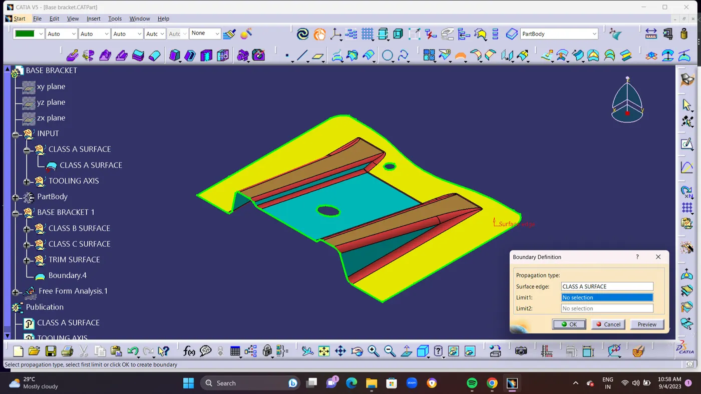
- STEP 1: Verify the connectivity of the Class A Surface Ensure that there is no gap between the component, using the Joint or Boundary command.We can visually check it or by clicking the boundary command.It has 3 boundaries one outer and two inner circle boundaries.In Between If It Shows Any Green Border It Seems The Surface As Gap Therefore first check was completed.
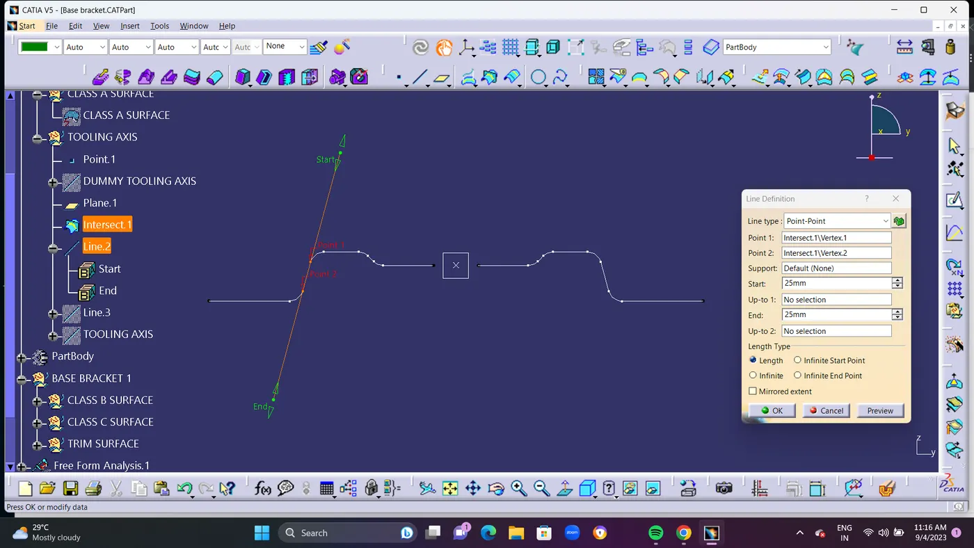
- STEP 2: The tooling axis is the direction in which the mold, core, or cavity opens.
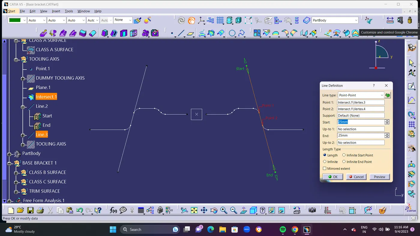
1.Sketch is drawn on the intersection curves.
2.Two lines are drawn at the outmost ends.(LINE 2,LINE 3)
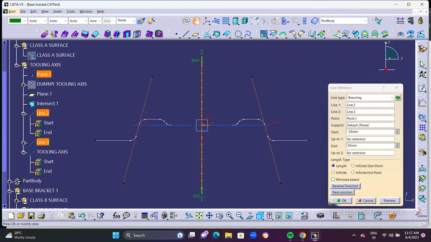
3.Both the lines are bisected and a line is created at the middle.
4.This is the tooling axis.
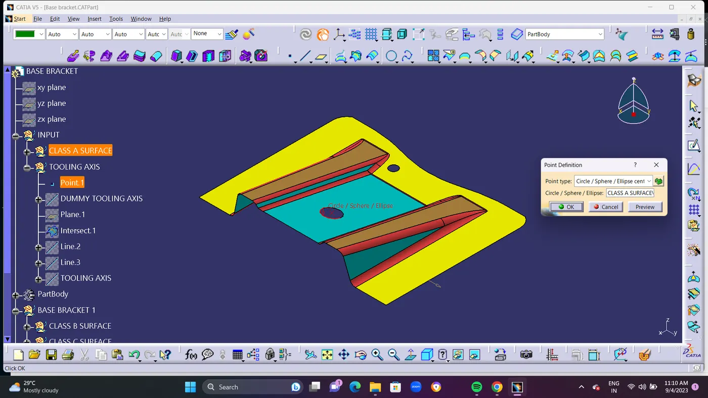
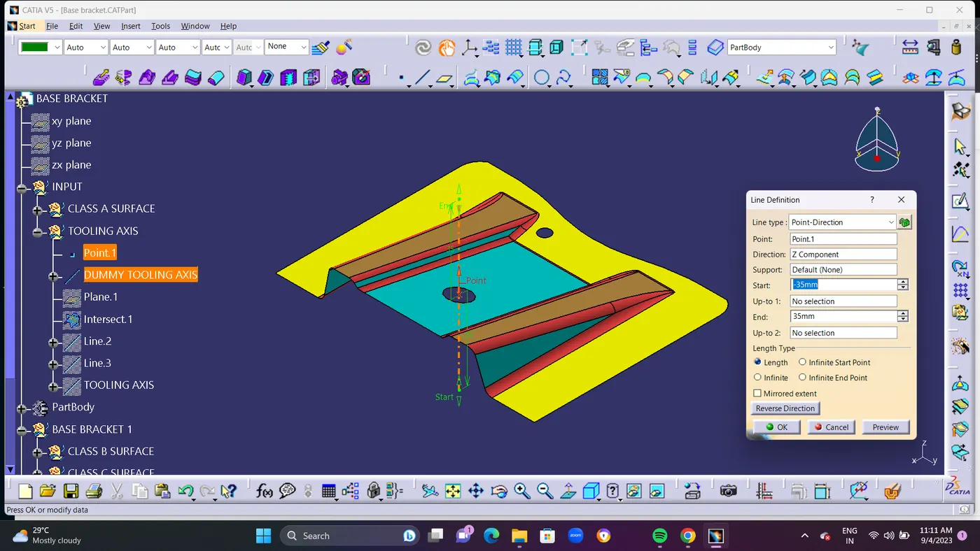
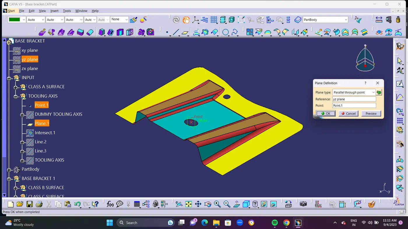
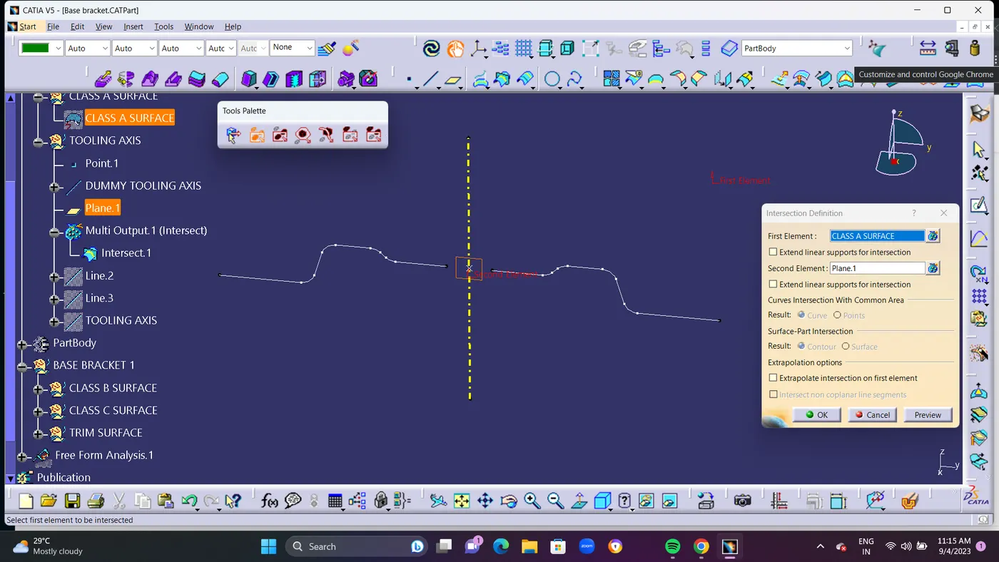
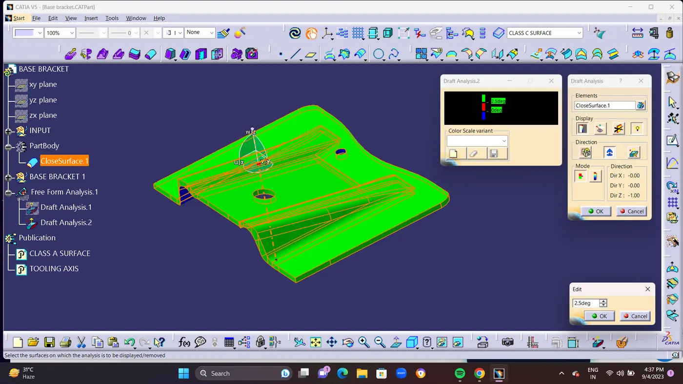
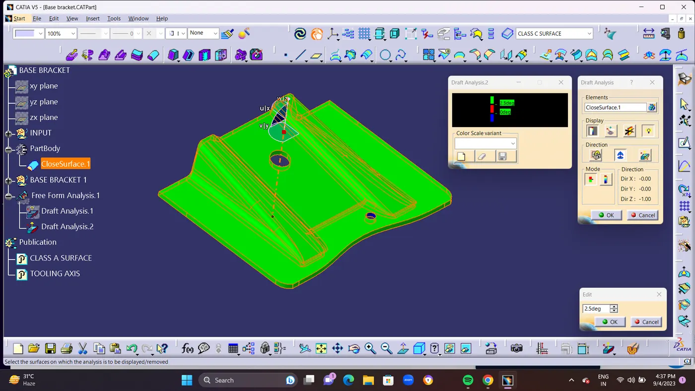
- STEP 3: In order to do a draft analysis, color ranges are used to indicate zones on the investigated element where any deviation from the draft direction correlates to certain values. The minimum draft angle is three degrees. Draft analysis is required to check if a part has required draft or not. Draft is required so that a part can be ejected from its mould easily.
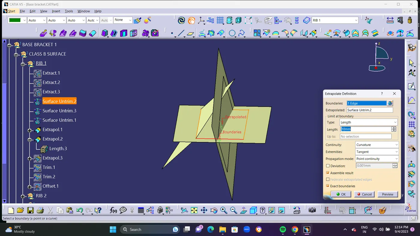
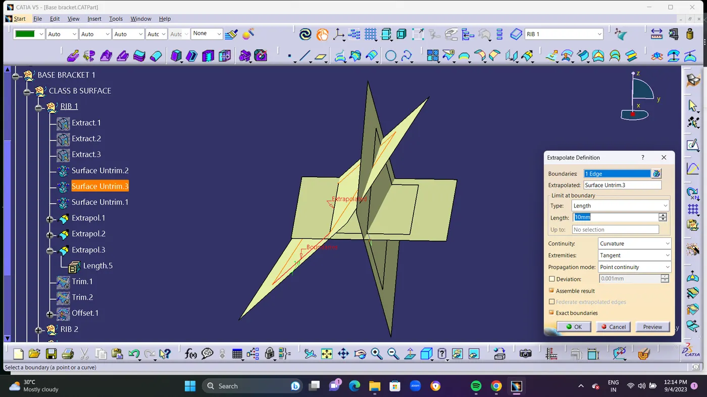
- STEP 4: To Creat B Surface First You Should Extract Rib 1 part From A surface so that you will get the extracted surface of B from A surface using Extract command by no propagation option EXTRACT 1,2,3. Extracting Use SURFACE UNTRIM For Extend the surface. Untrim Surface extends an existing surface, whereas Surface Fill creates different surfaces, applies a patch between multiple faces, uses constraint curves, and so on.And use the command called Extrapolation is an operation in which an element is extended a specified amount while respecting tangency or curvature conditions.Typically a surface boundary can be selected for in order to extrapolate the surface a specified length. You can extrapolate a surface boundary.
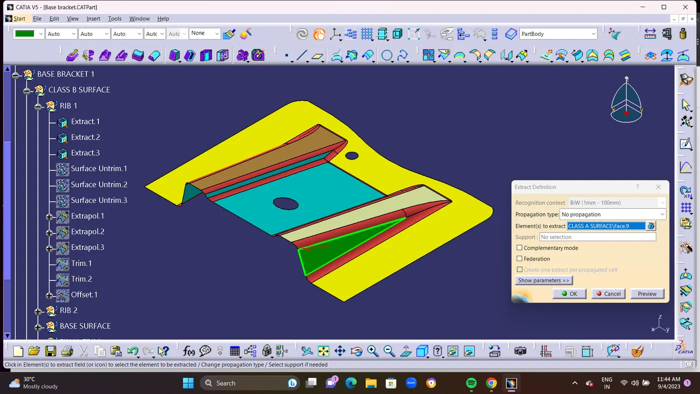
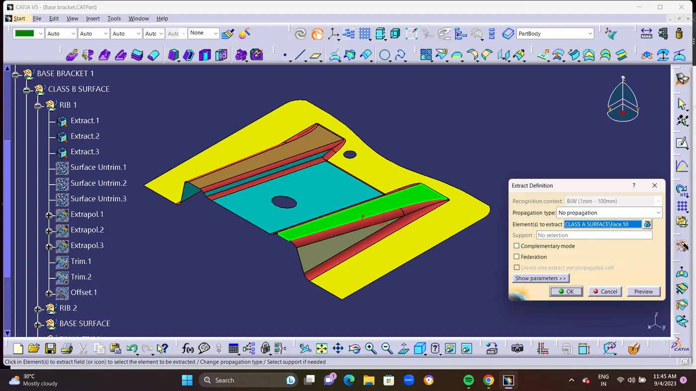
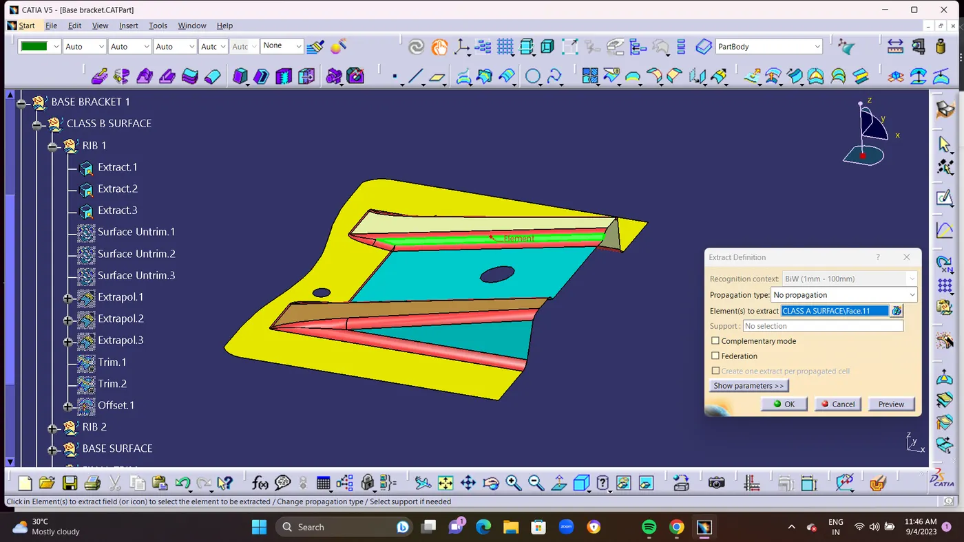
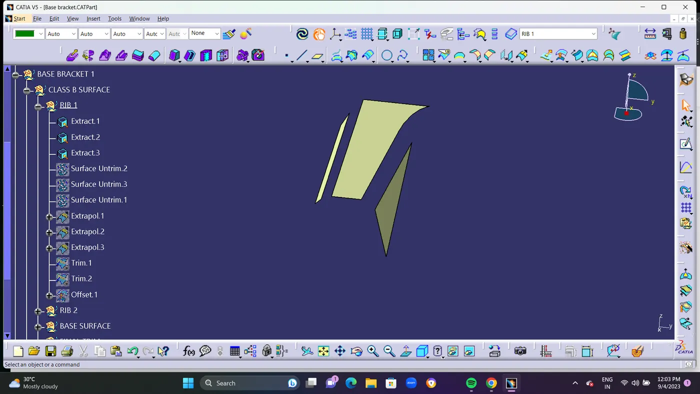
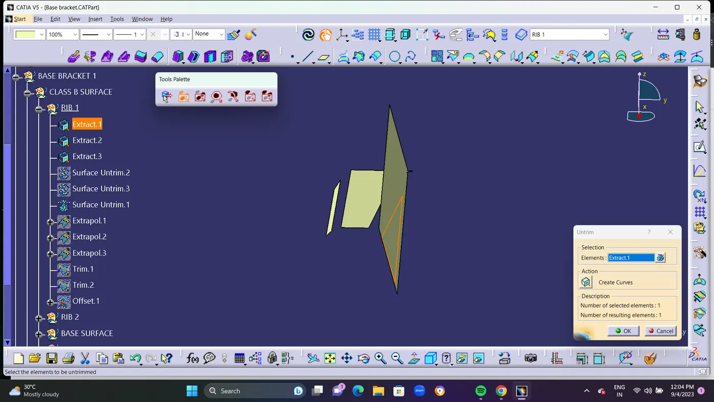
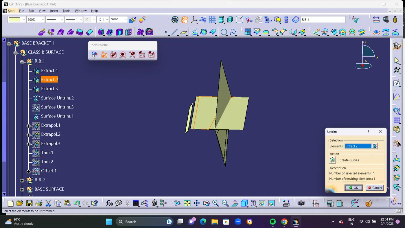
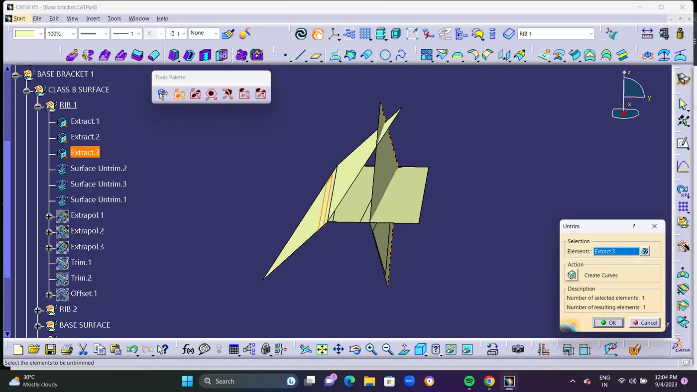
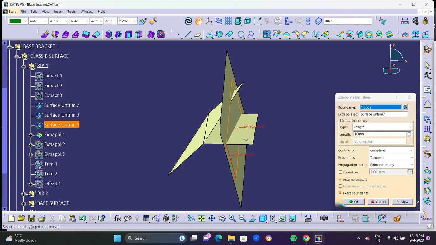
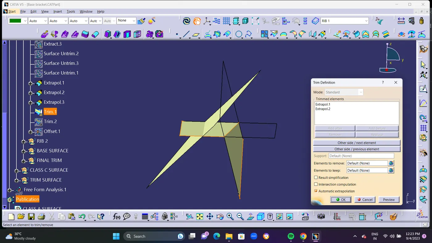
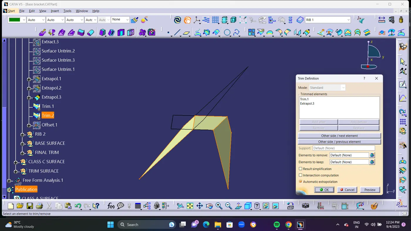
- STEP 5: Using Trim option unwanted surface as been removed from the Rib 1 and it is offset by 2.5mm from the extracted surface. Trim the two surfaces or wireframe elements you want to trim. The list of cut elements is updated, and a preview of the trimmed elements appears: By selecting the portion to be kept, you can adjust it: To trim the surfaces or wireframe pieces, click OK. Trim is the name of the trimmed feature. You can modify it by typing a new value in this field.when offsetting a face, specify whether you want to intersect and offset or to project and offset the face by selecting the appropriate option from the list.
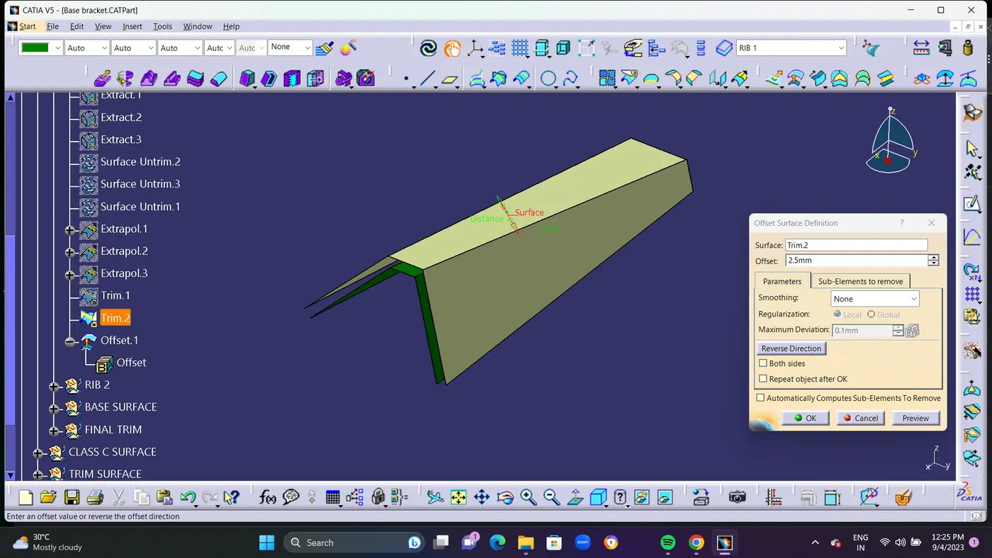
- STEP 6: Same as Rib1 Making RIB 2 Process.
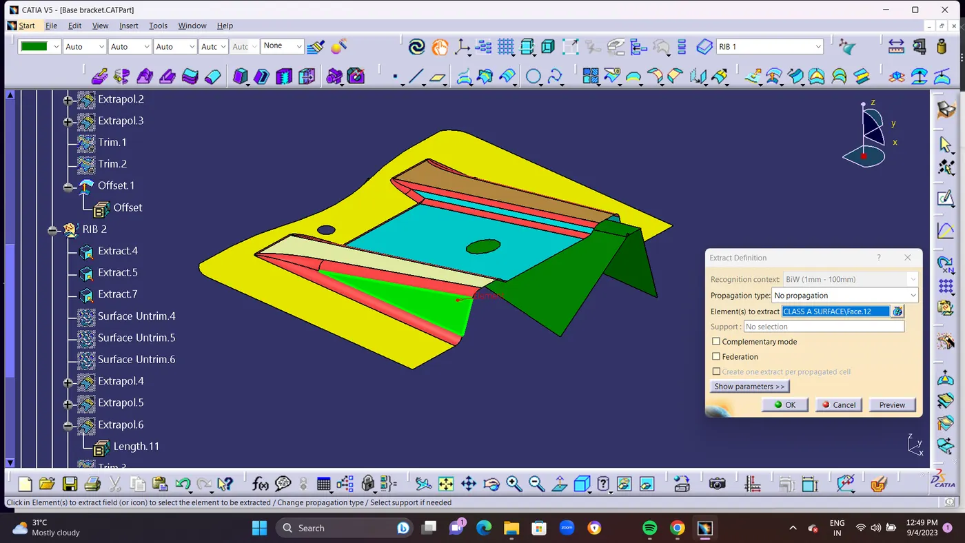
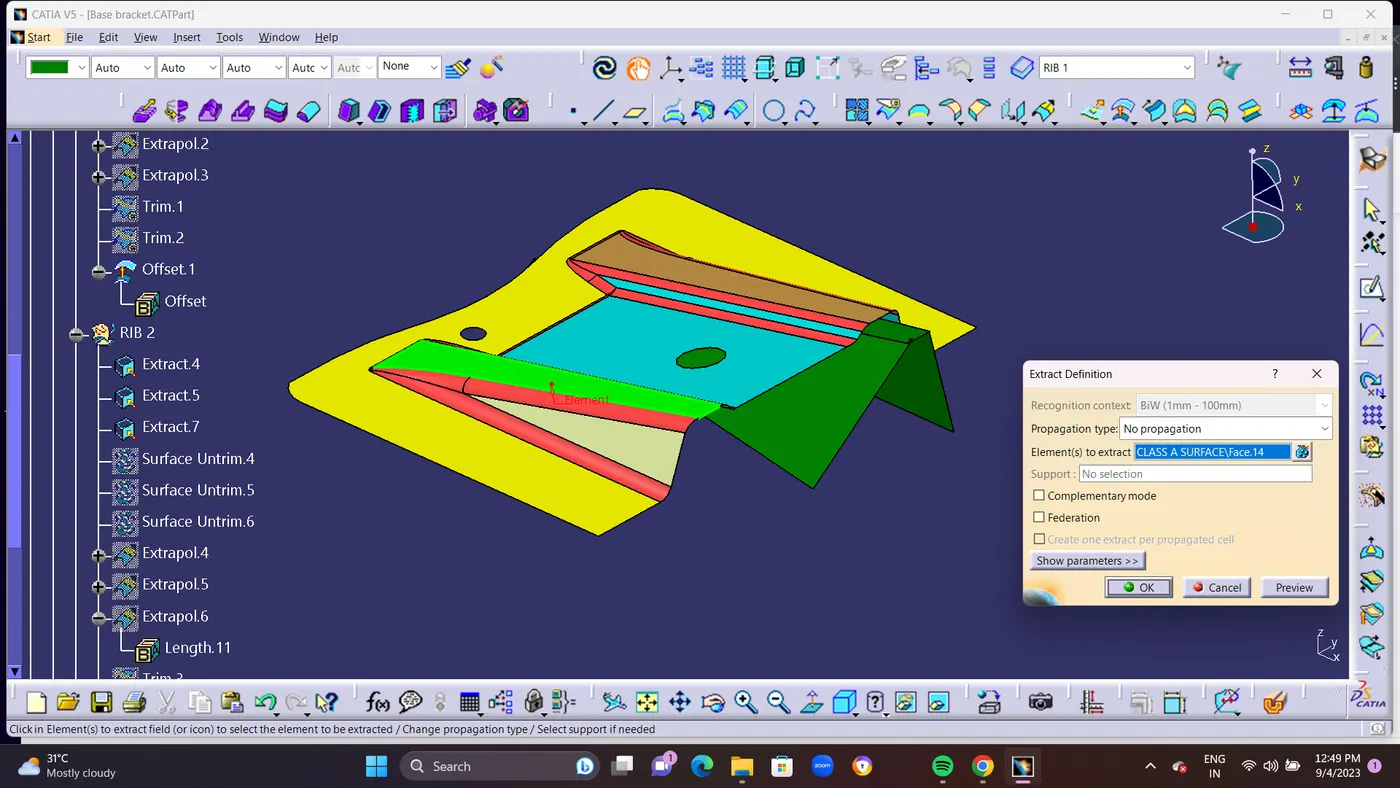
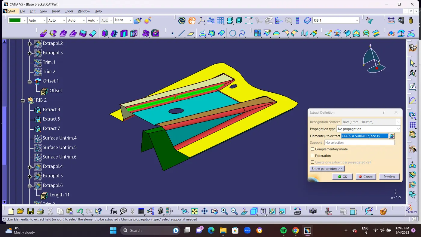
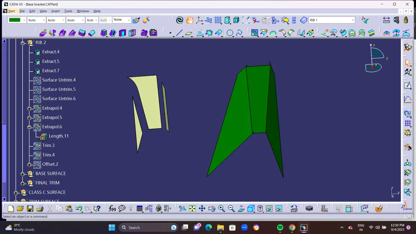
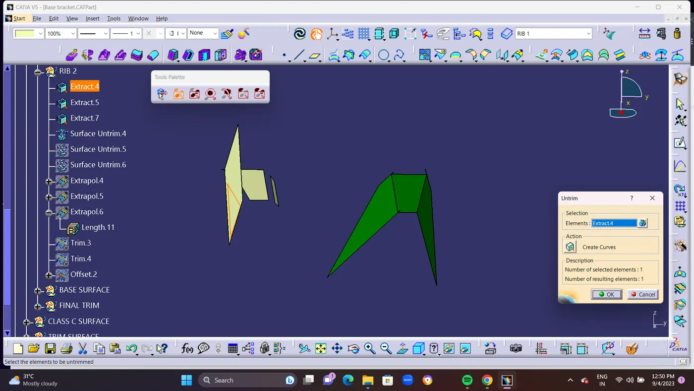
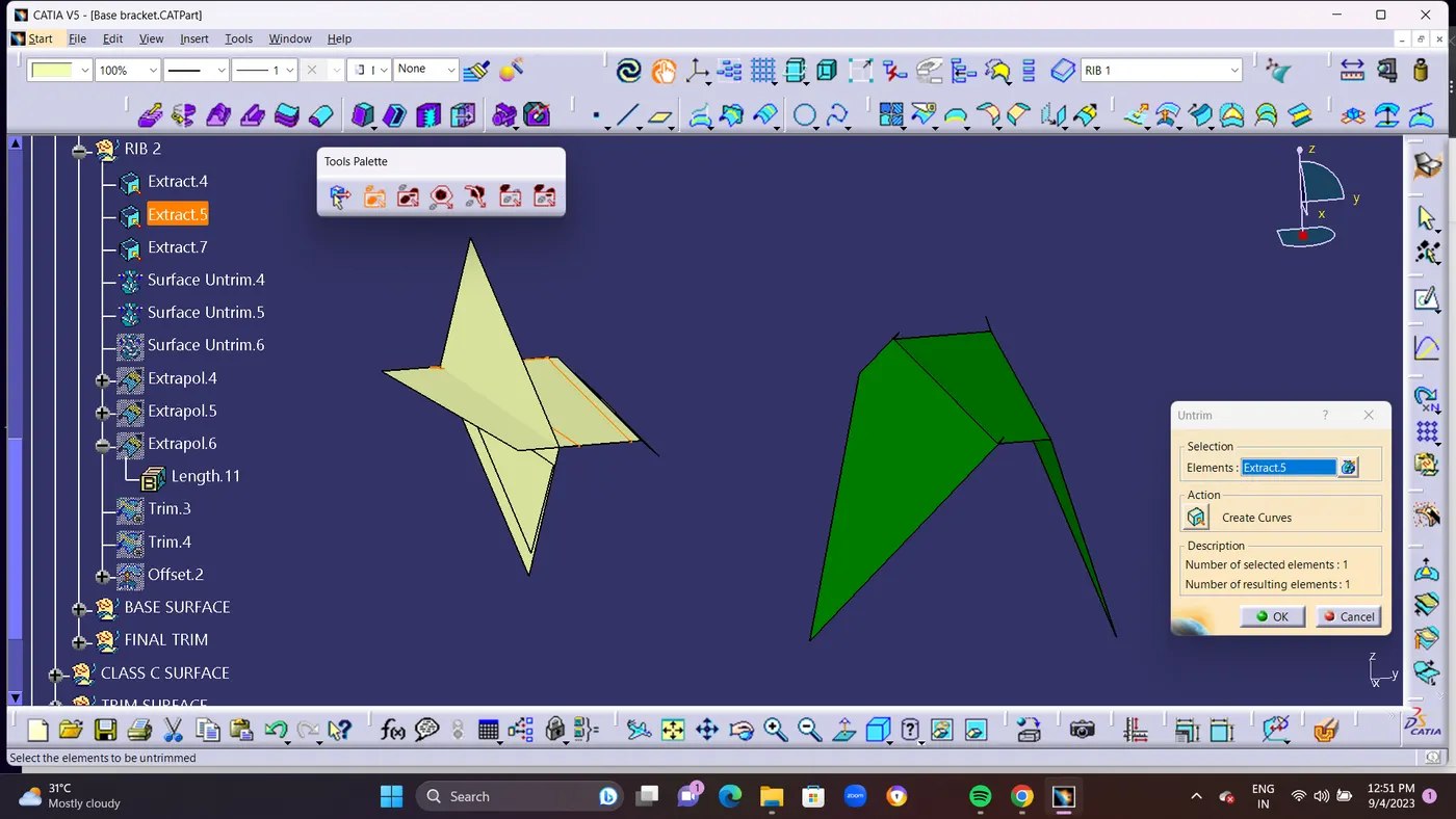
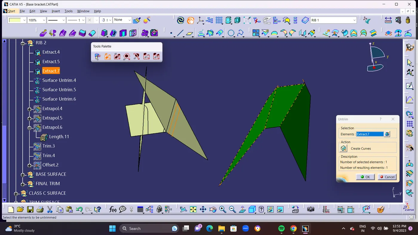
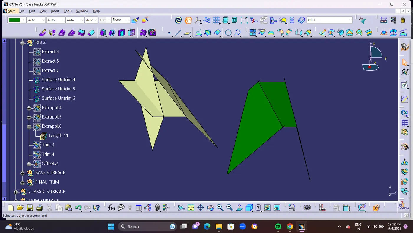
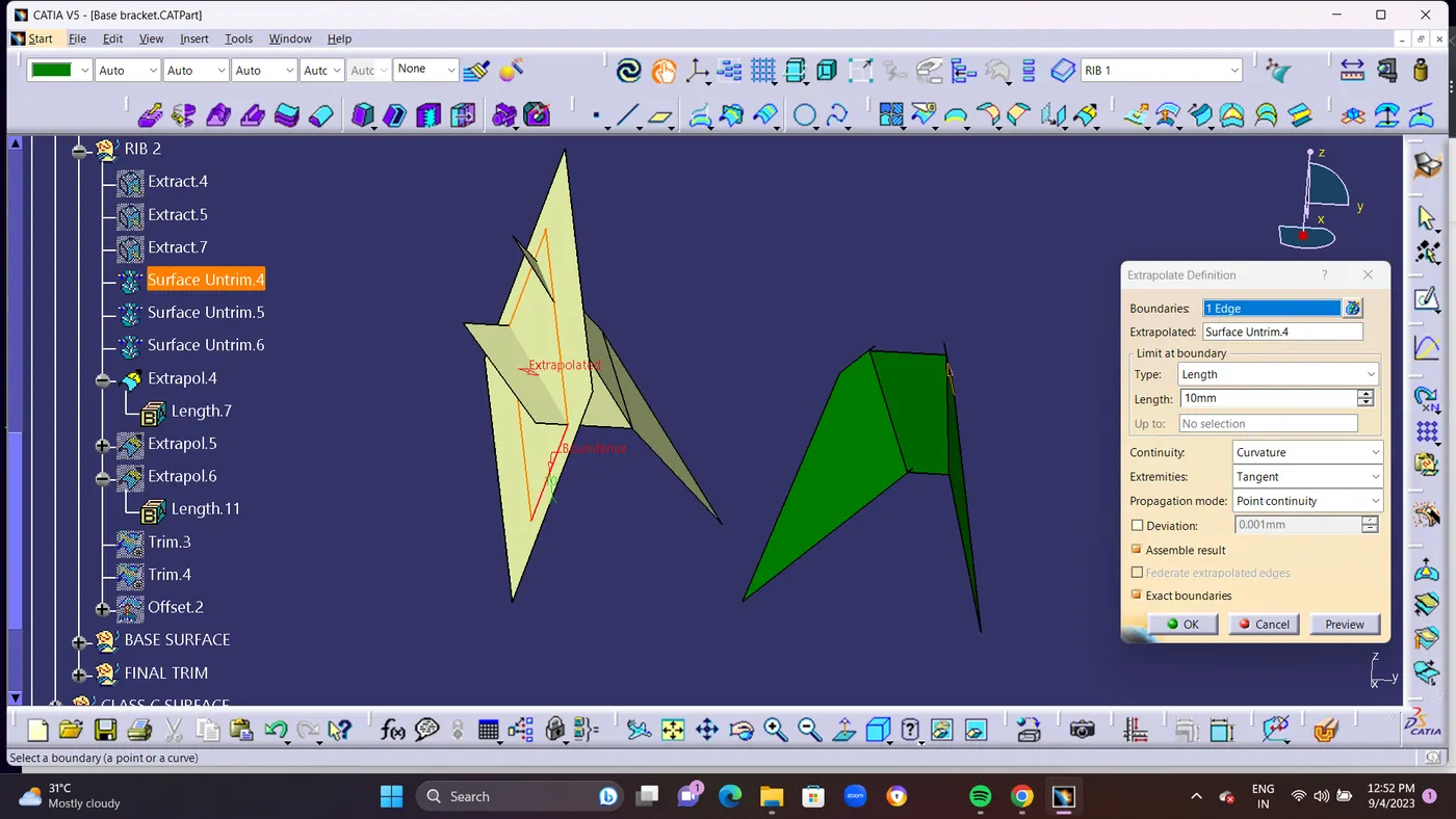
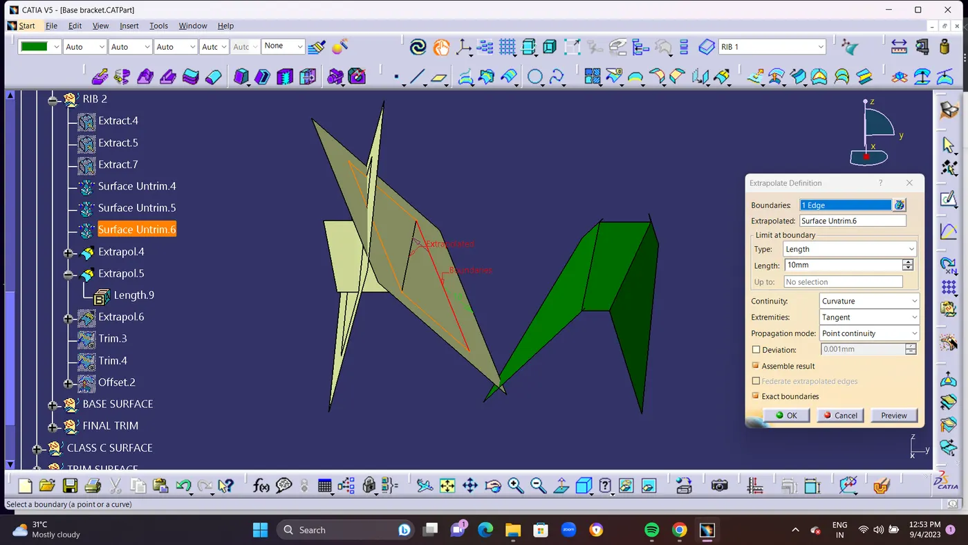
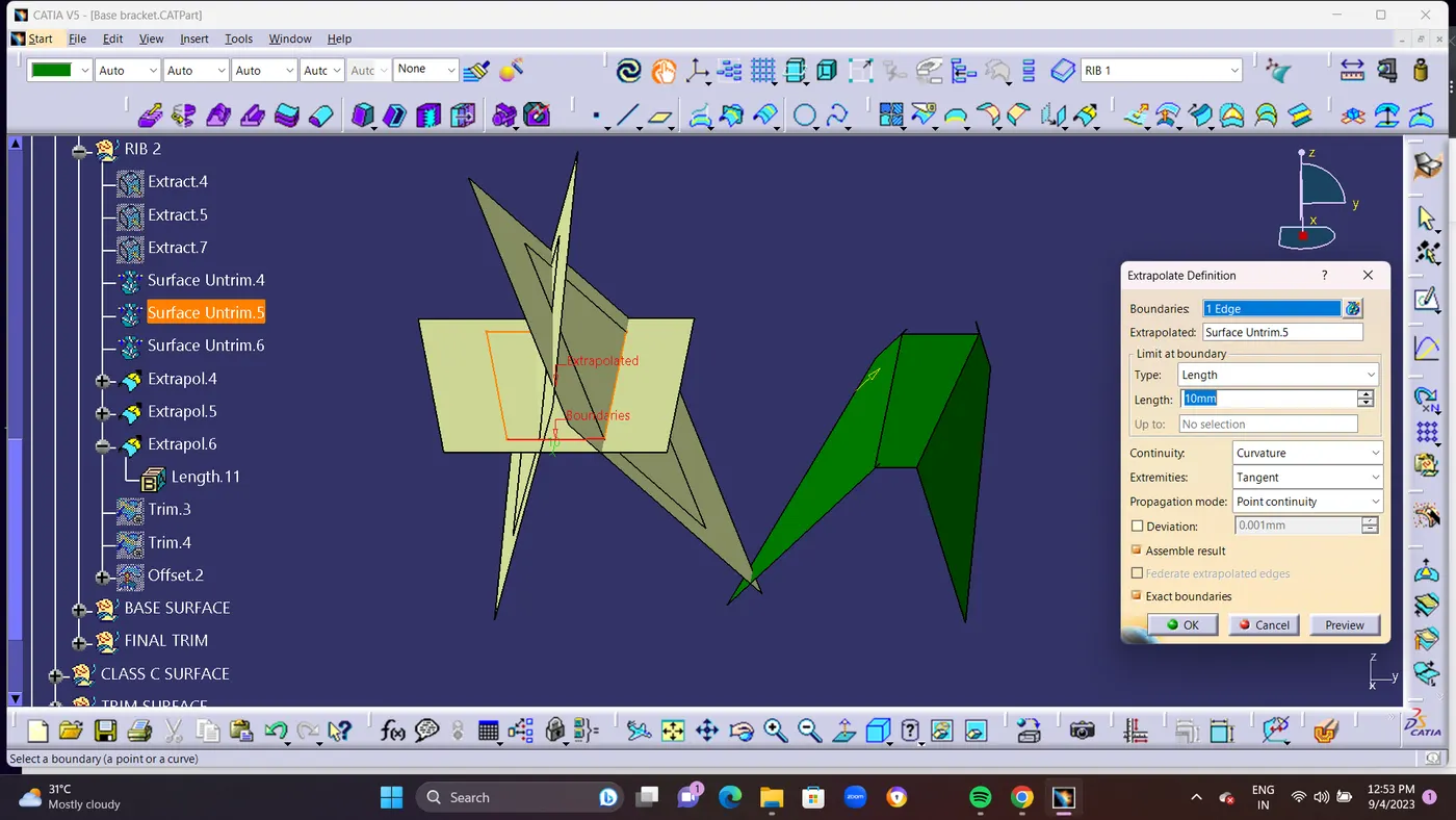
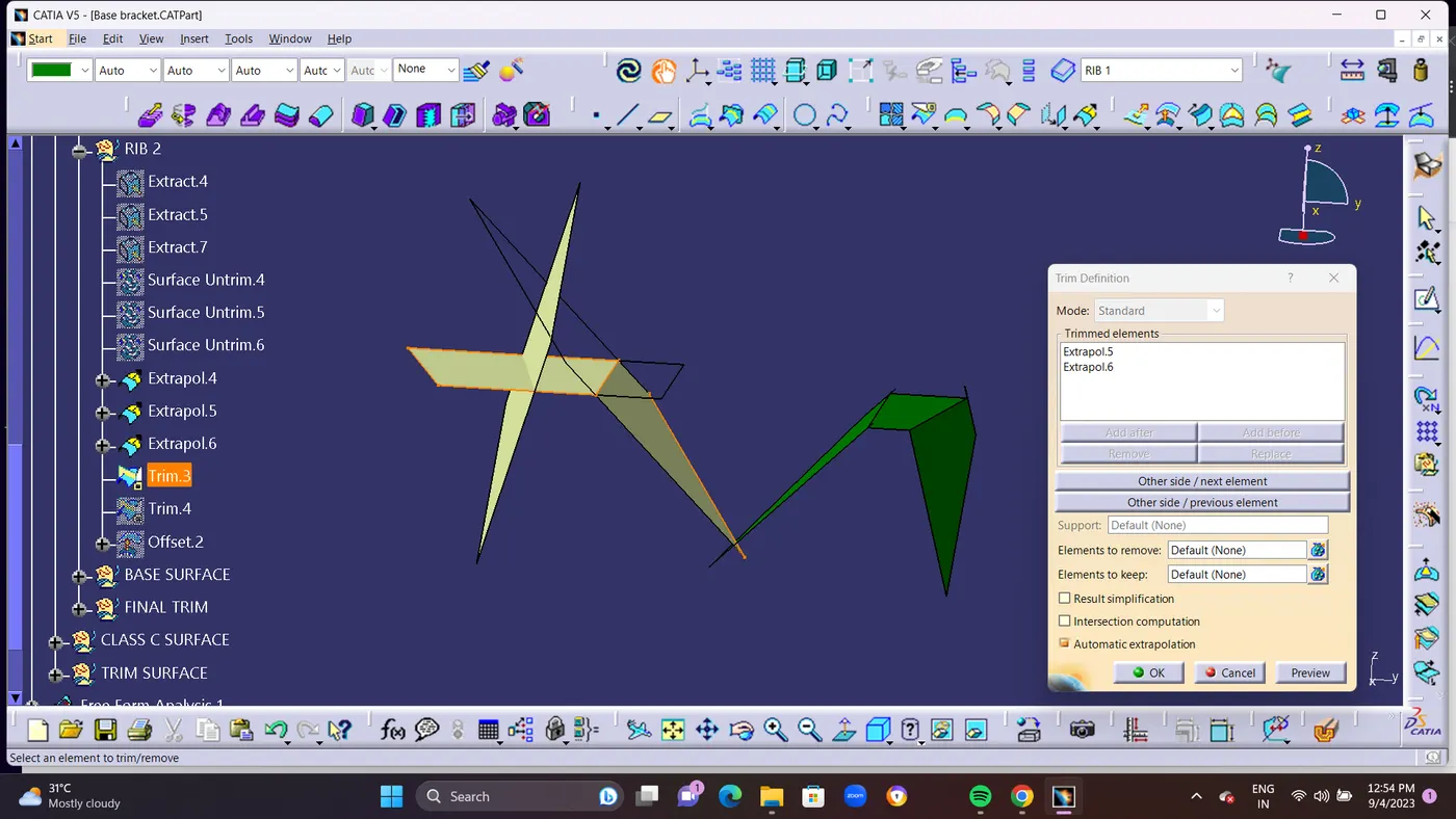
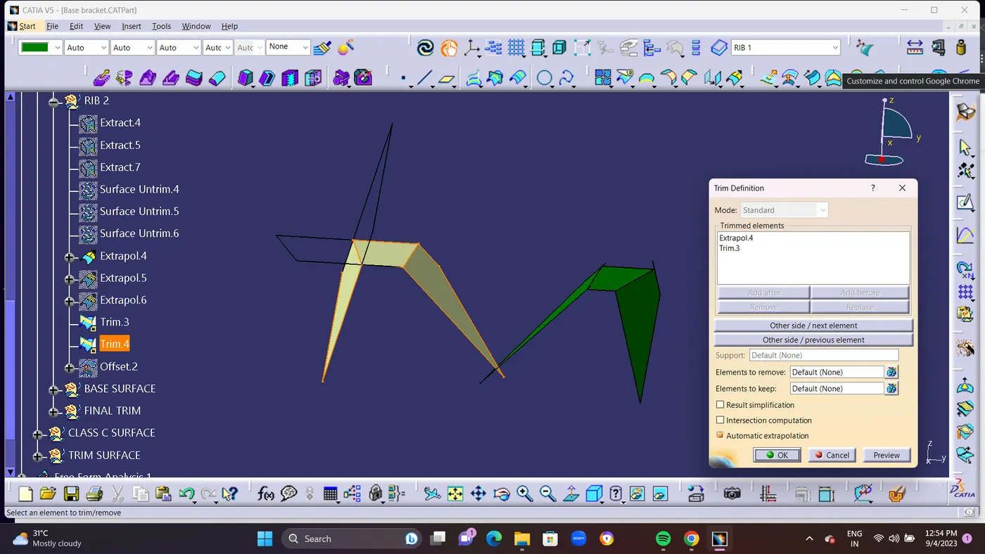
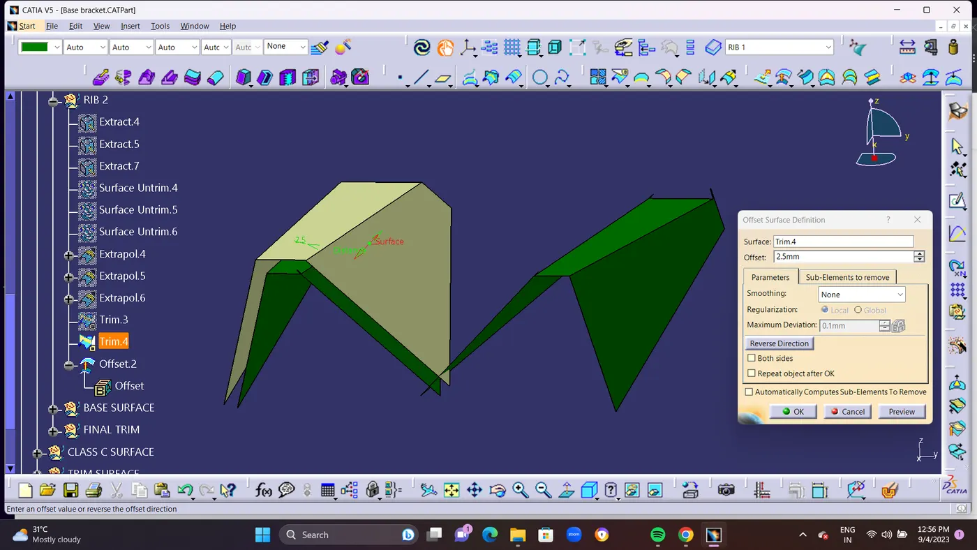
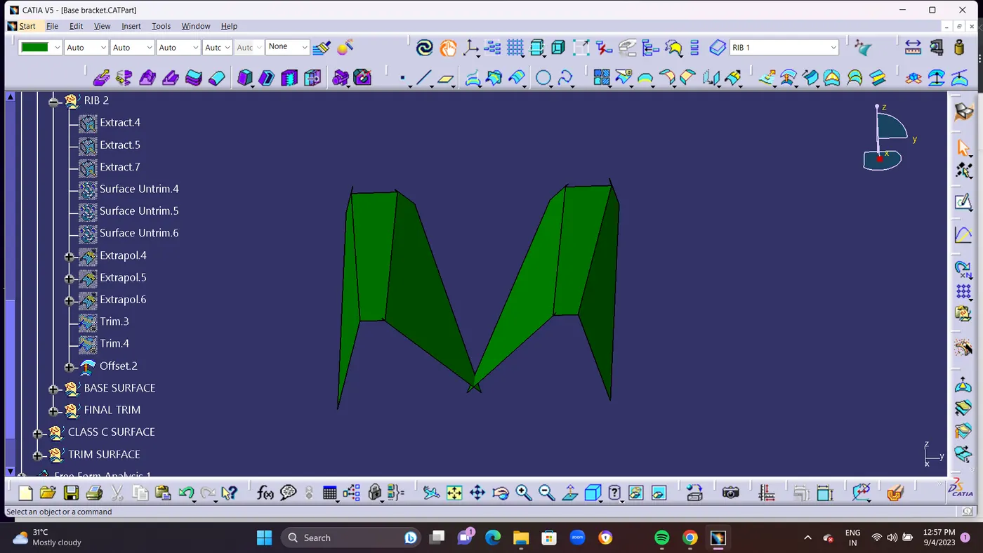
- STEP 7: After Ribs Completed Next we should work with RIBS connecting Surface by Extracting Class A Surface for Class B one.after Extracted We should offset it for 2.5mm and Untrim the surface 7.and Work with Base Surface Extract Base Surface from Class A surface and Offset it for 2.5mm.Untrim the Base surface 8 and Extrapolate it.
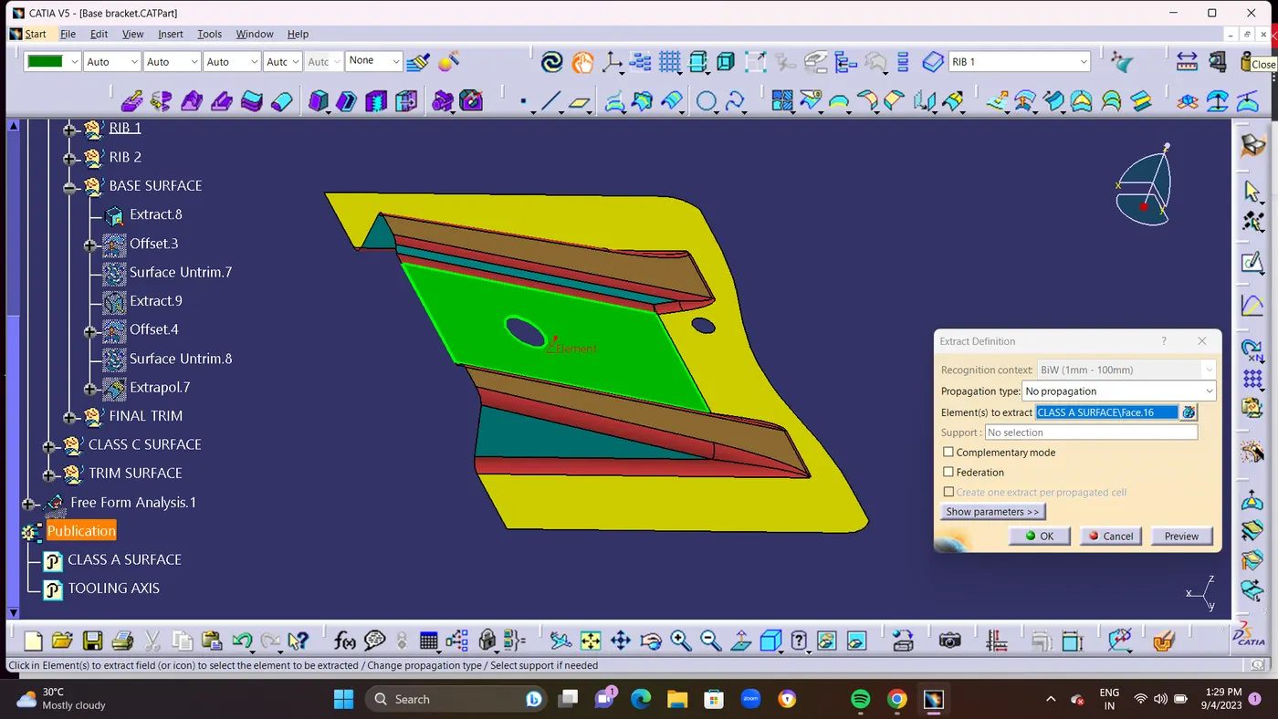
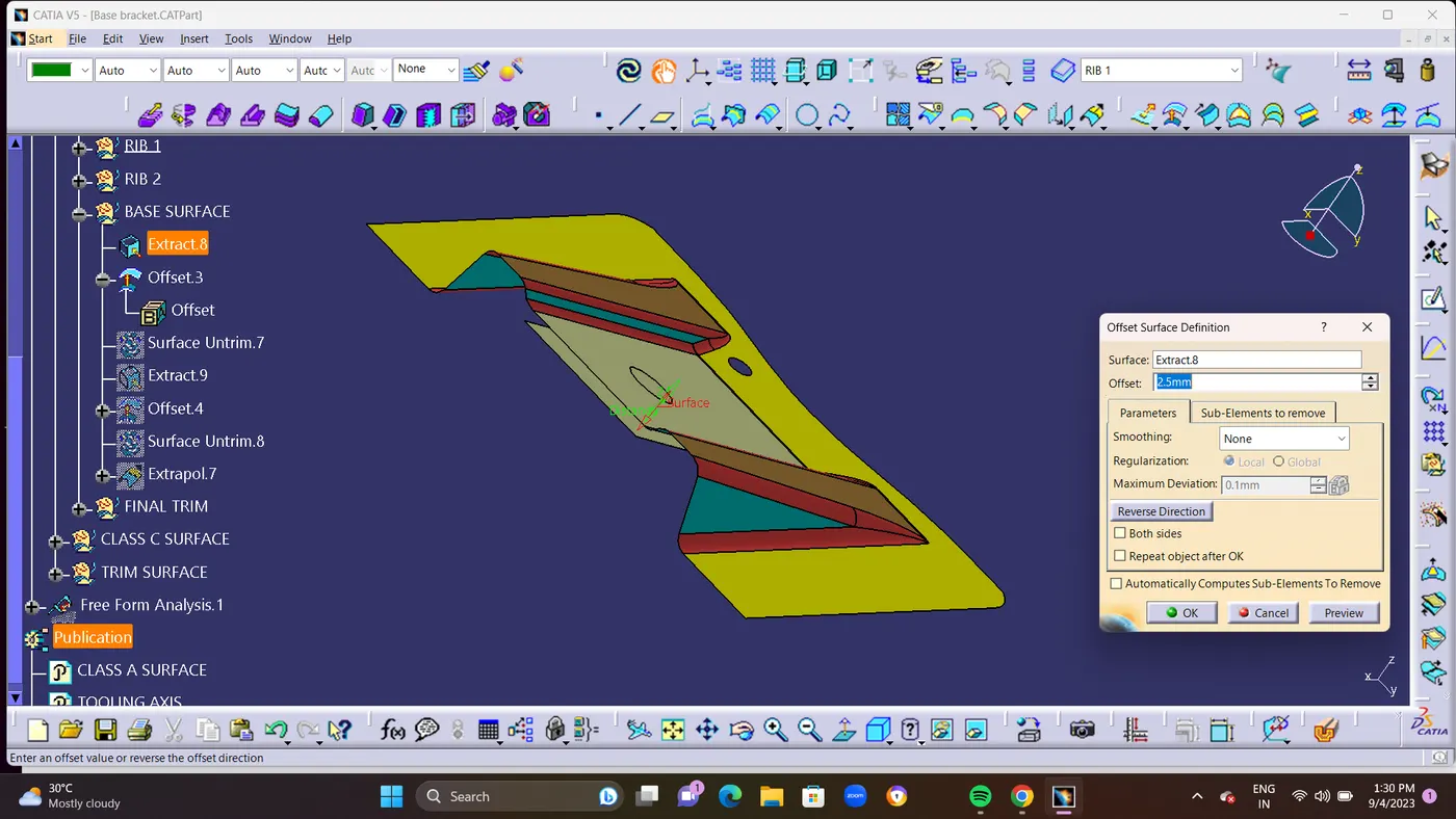
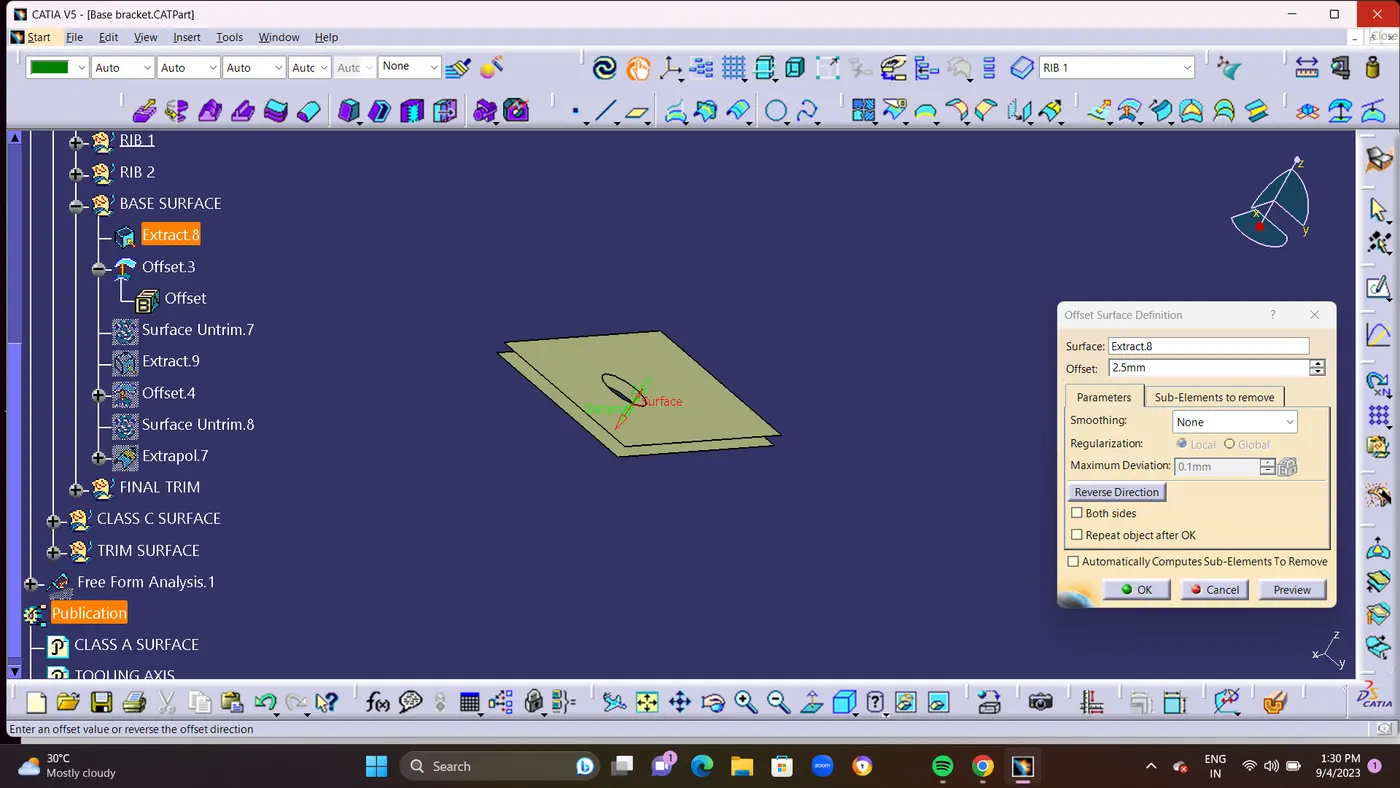
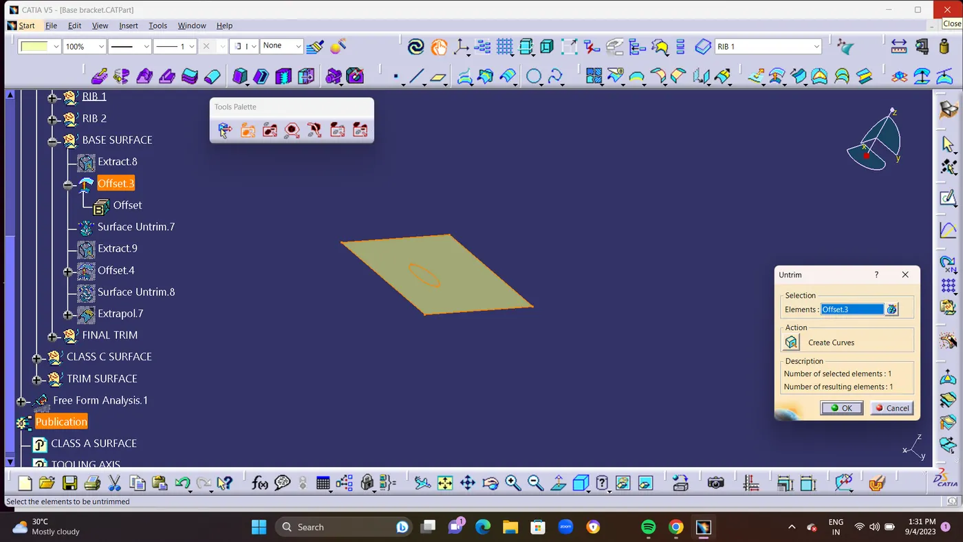
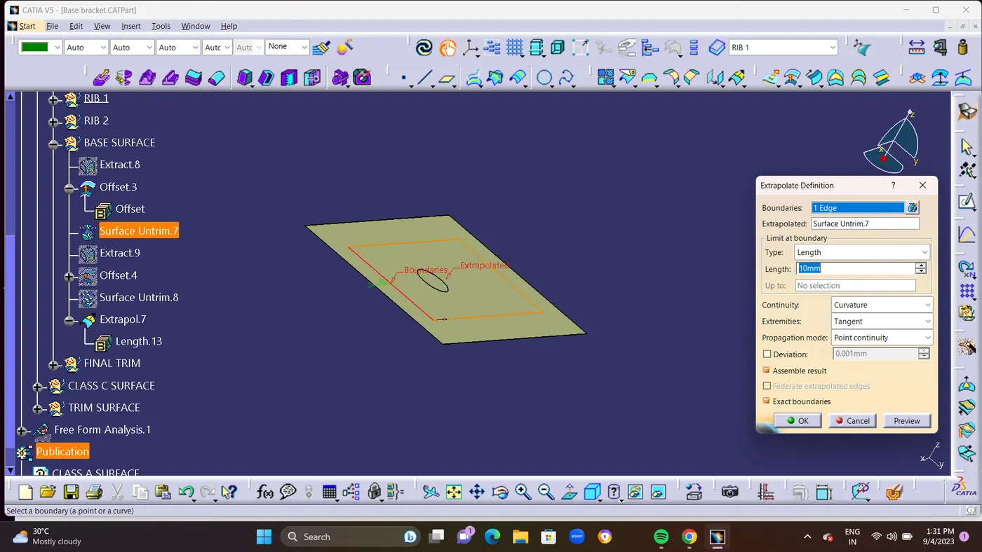
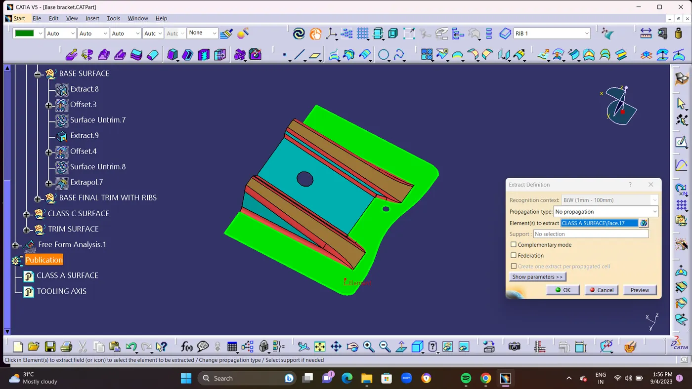
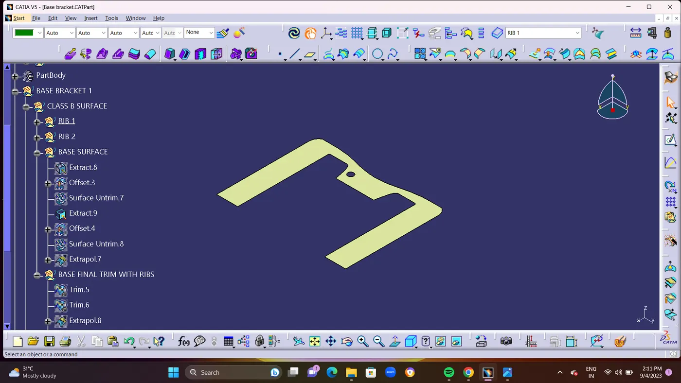
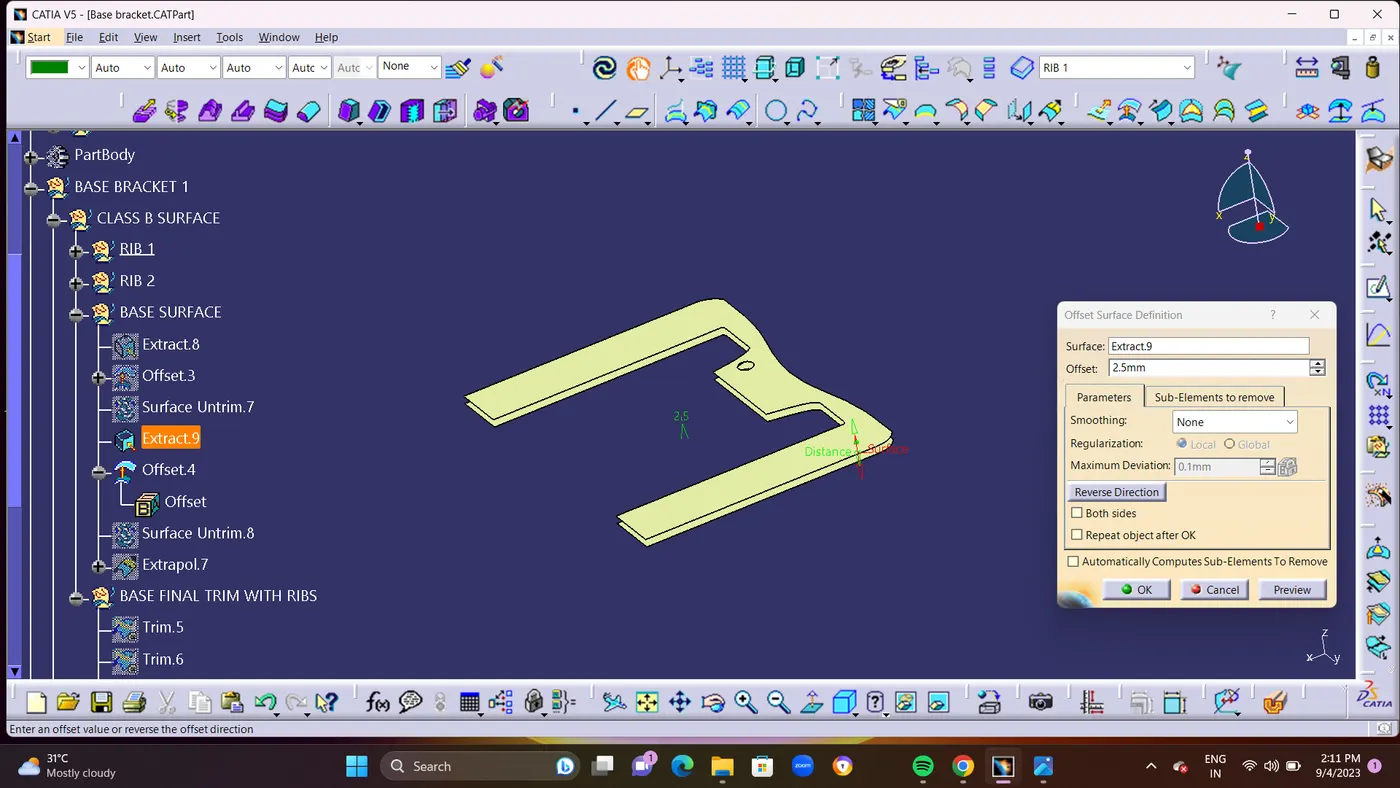
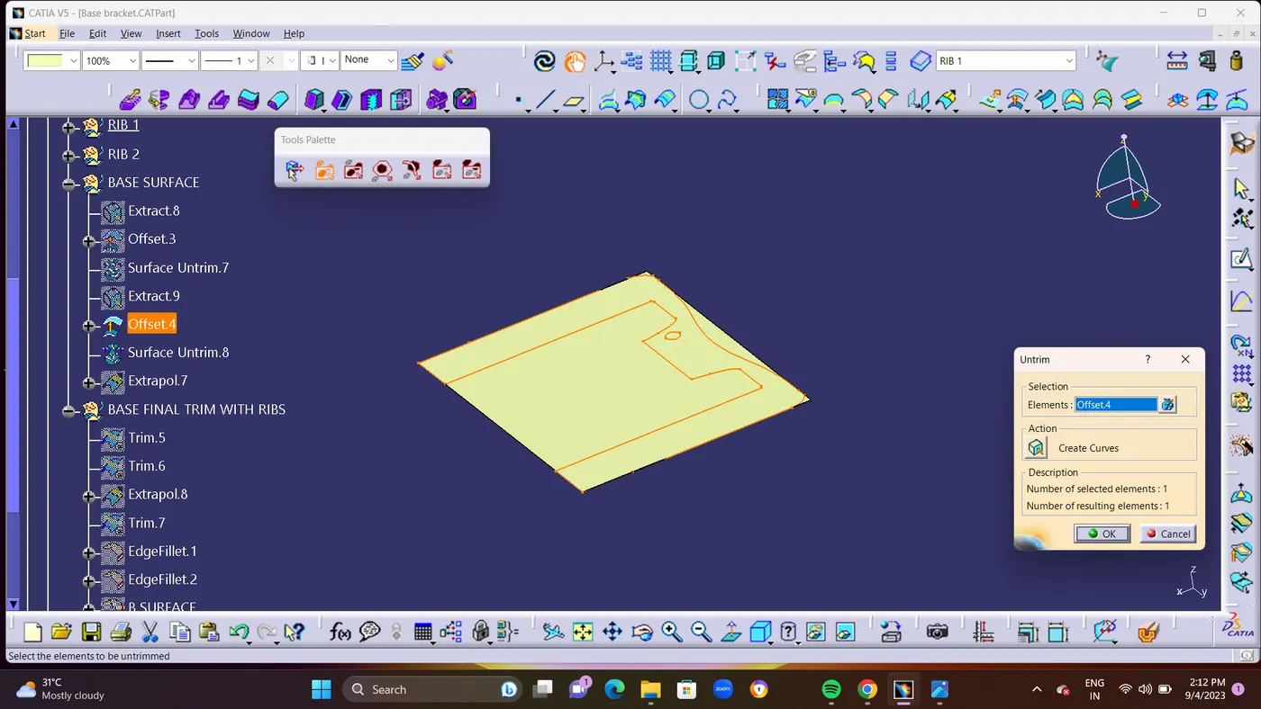
- STEP 8: We used to TRIM RIB Connecting Surface With RIB 1 and RIB 2 and Finally TRIM with Base Surface. And The Final Out Put Will be as Class B Surface.
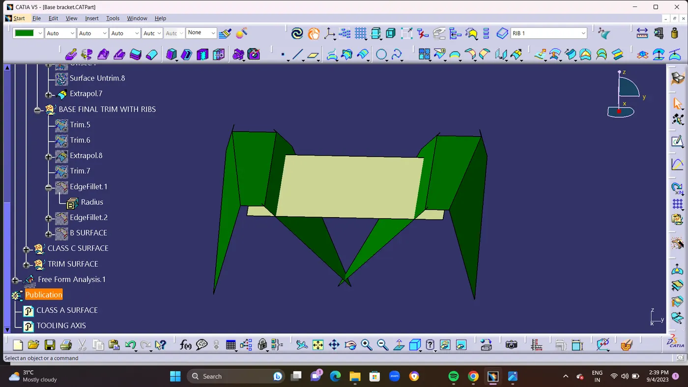
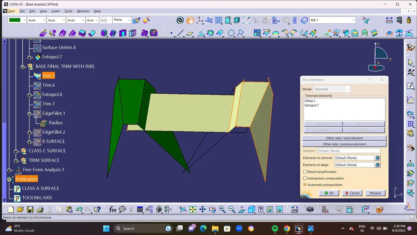
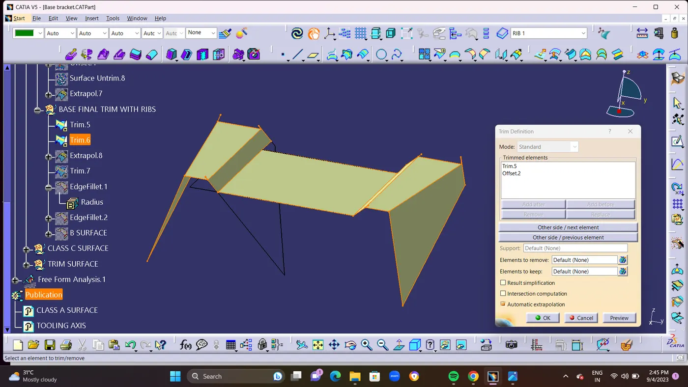
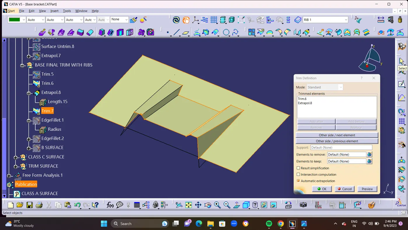
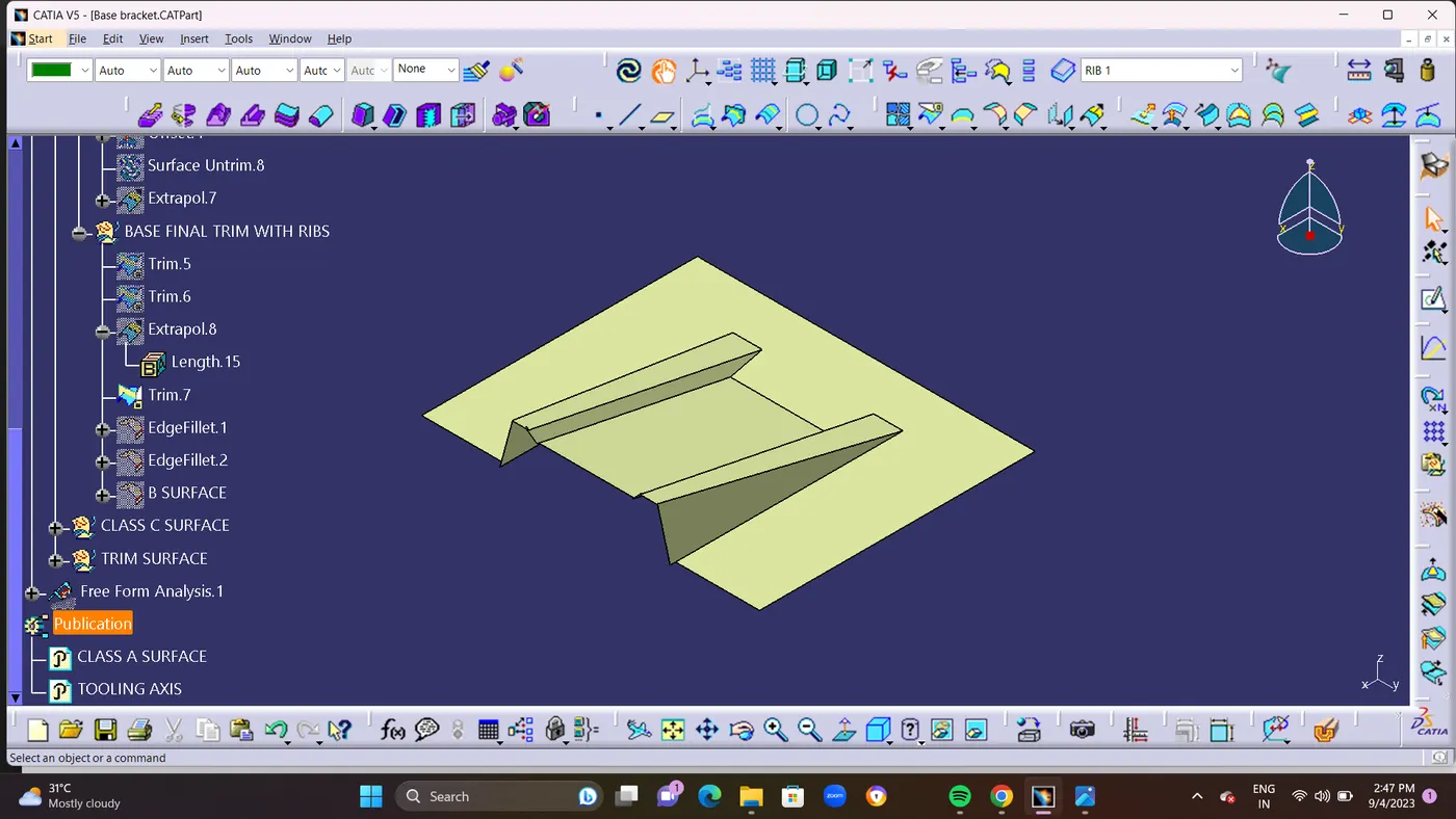
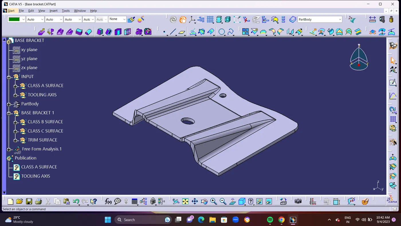
- STEP 9: In order to add FILLETS to the surface B, which is an exact replica of class A but at a distance of 2.5mm Gap and does not have any Fillet, a value of radius+thickness of the component, of 3+2.5=5.5mm, was provided for All Fillet area.The final surface created is shown below and is surface B
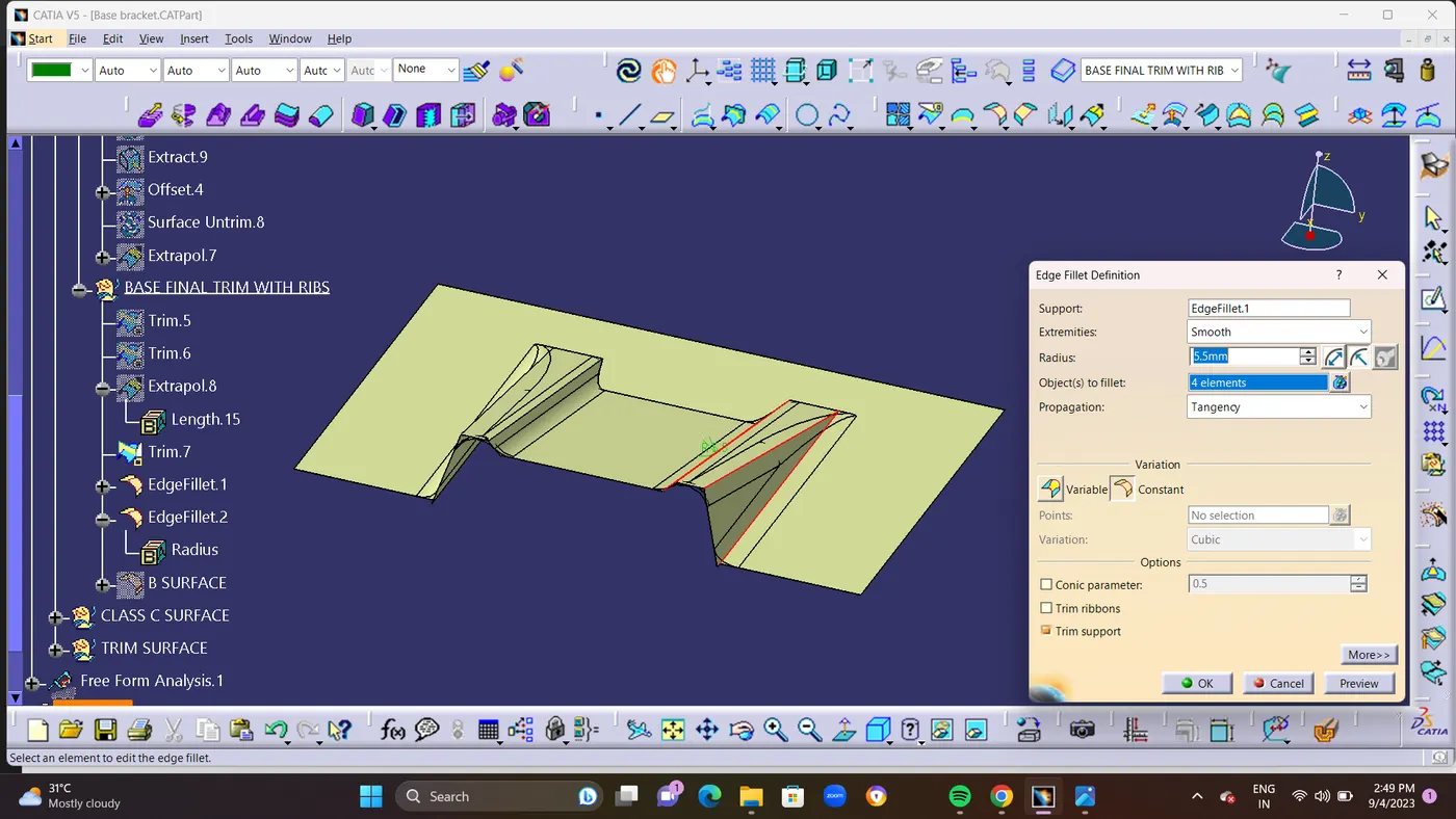
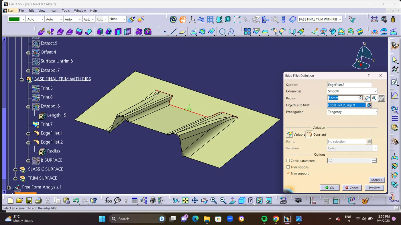
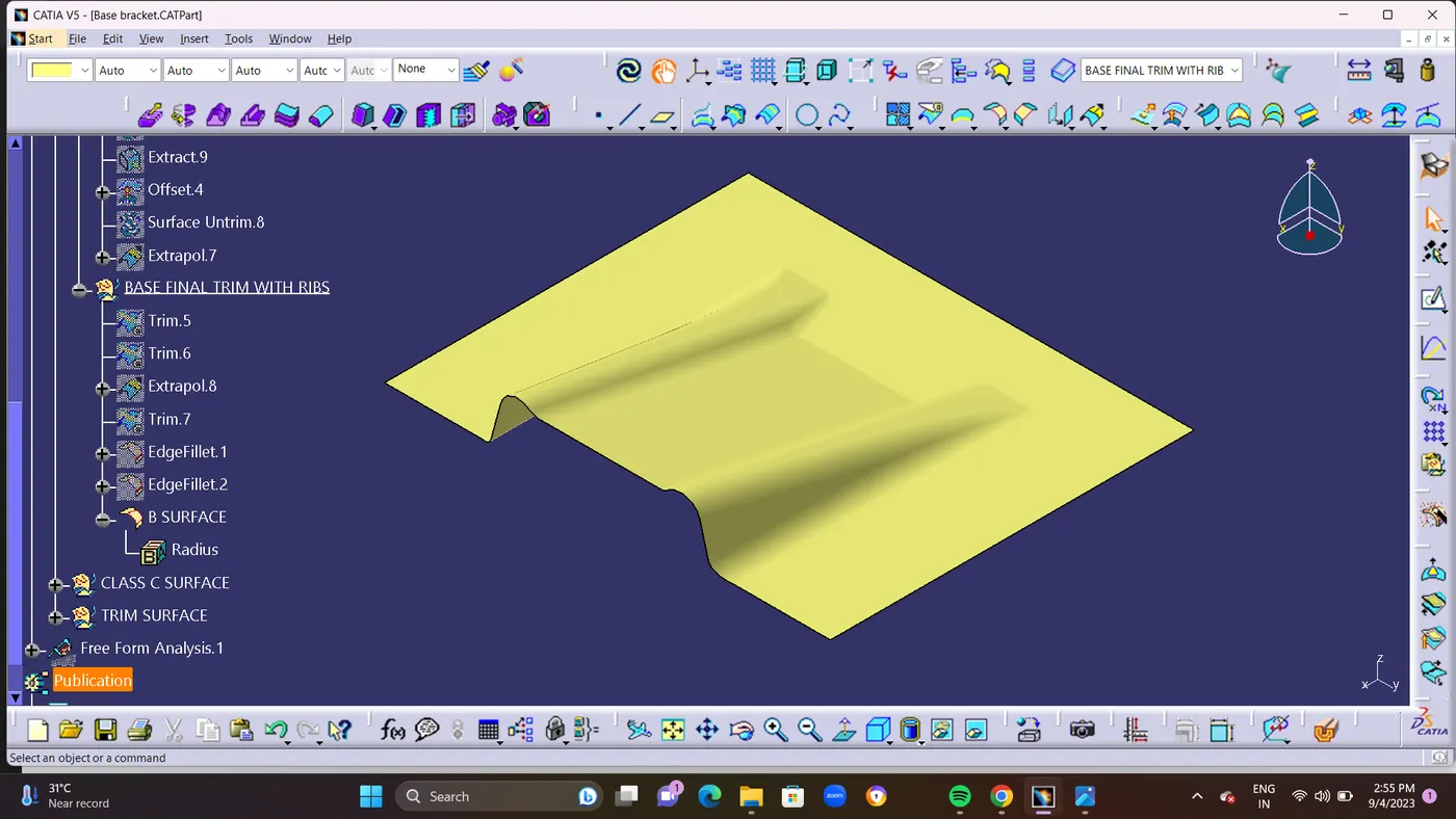
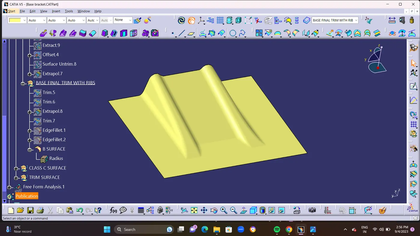
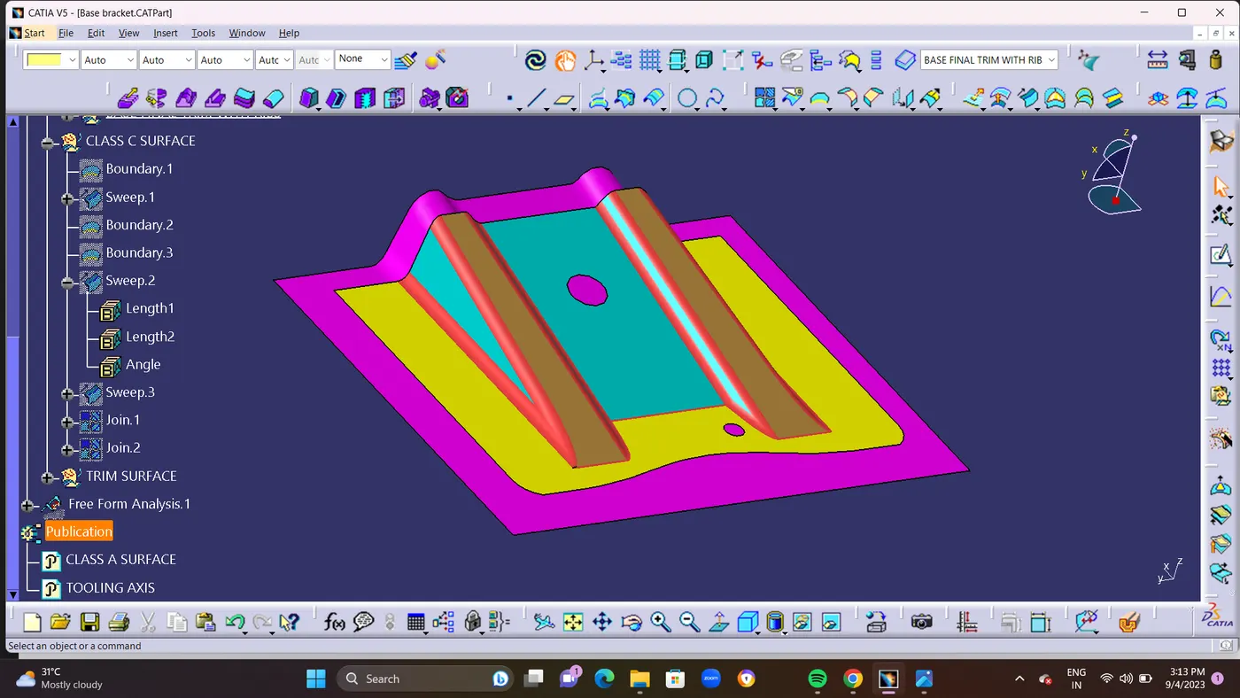
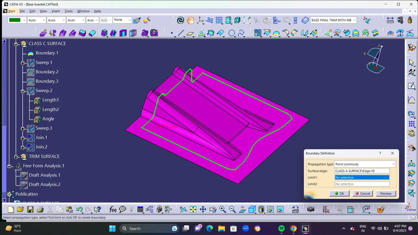
- STEP 10: The boundary was developed by taking class A into account.
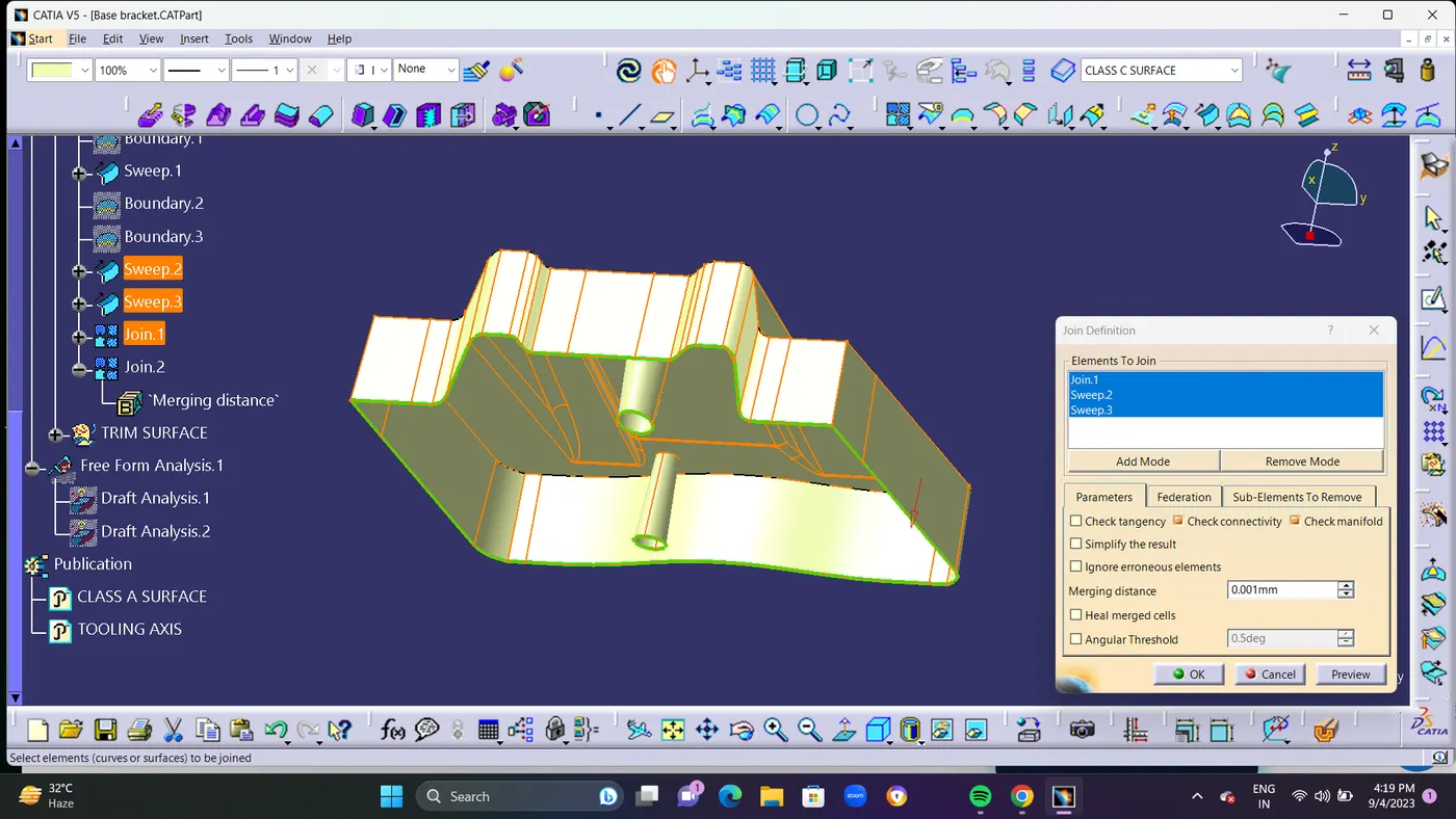
To build a Class C surface, the sweep command was used, and as a point of reference Line, the primary tooling axis and tooling direction were taken into account. Sweep Command is used to Extend the Border of Class A surface to make Class C surface and two inner Circle or Holes also Created by taking Boundary line and Extended with Sweep command.
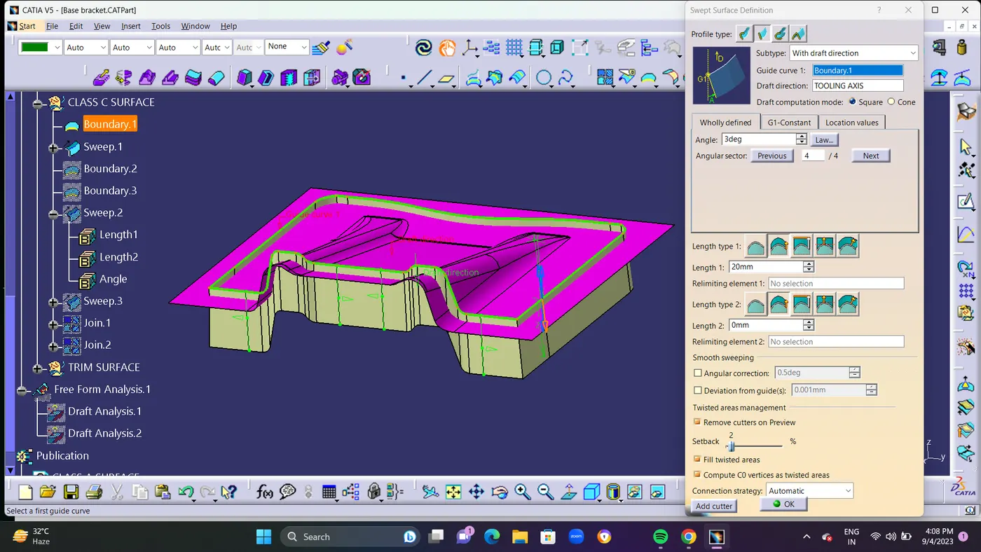
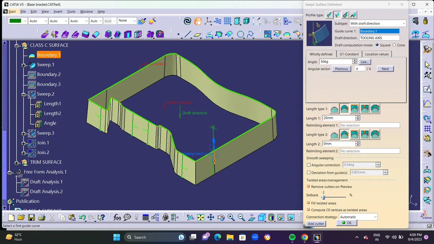
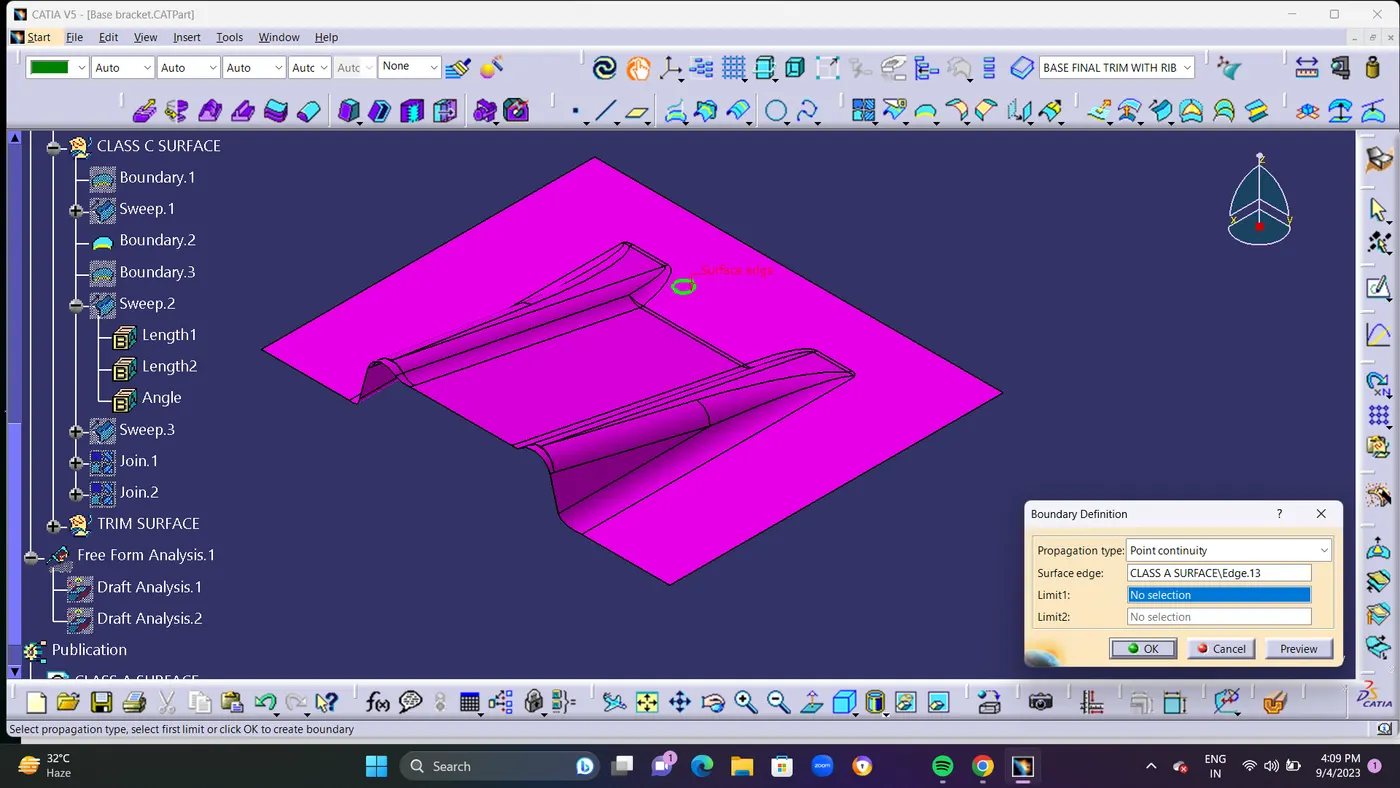
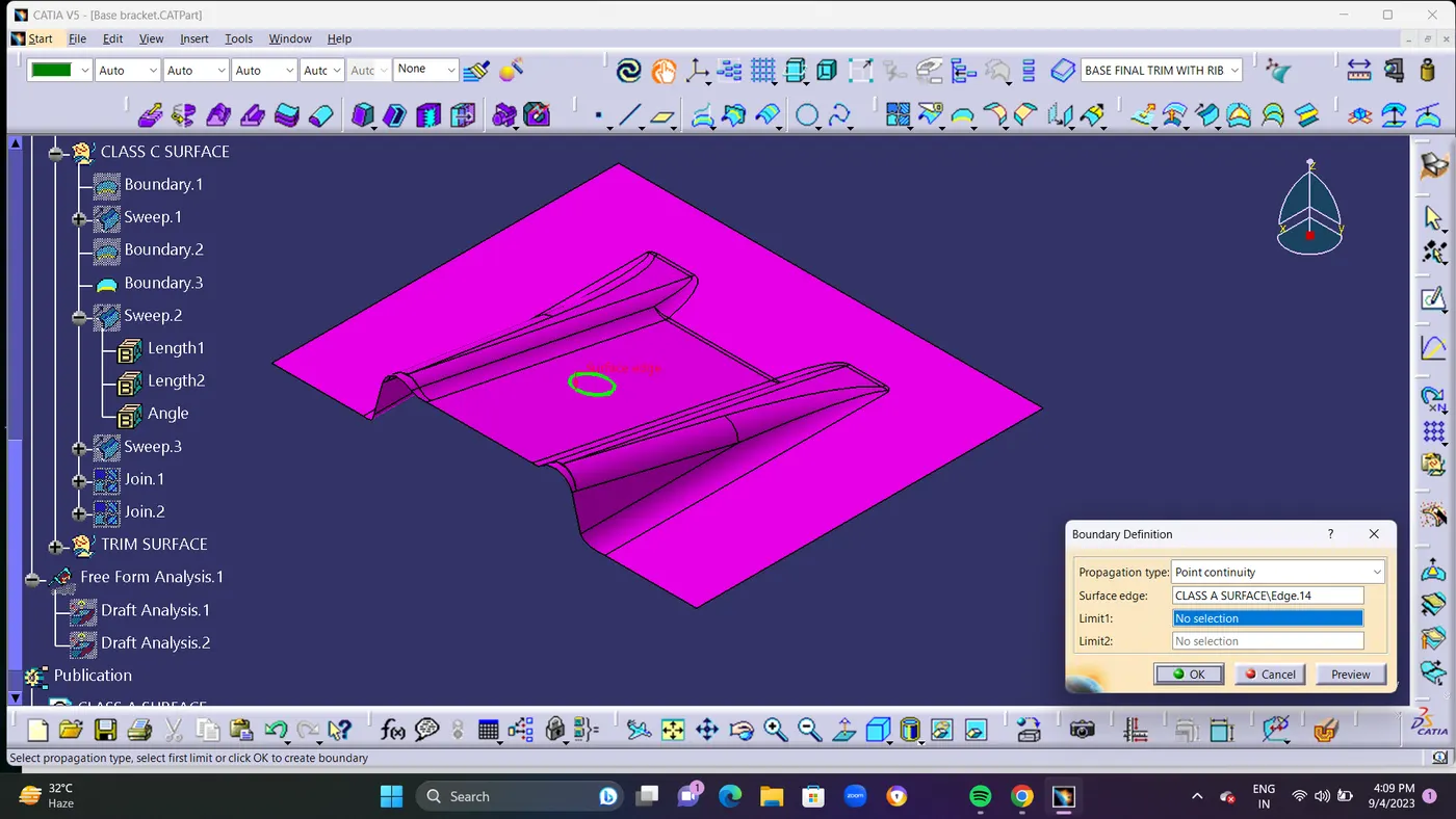
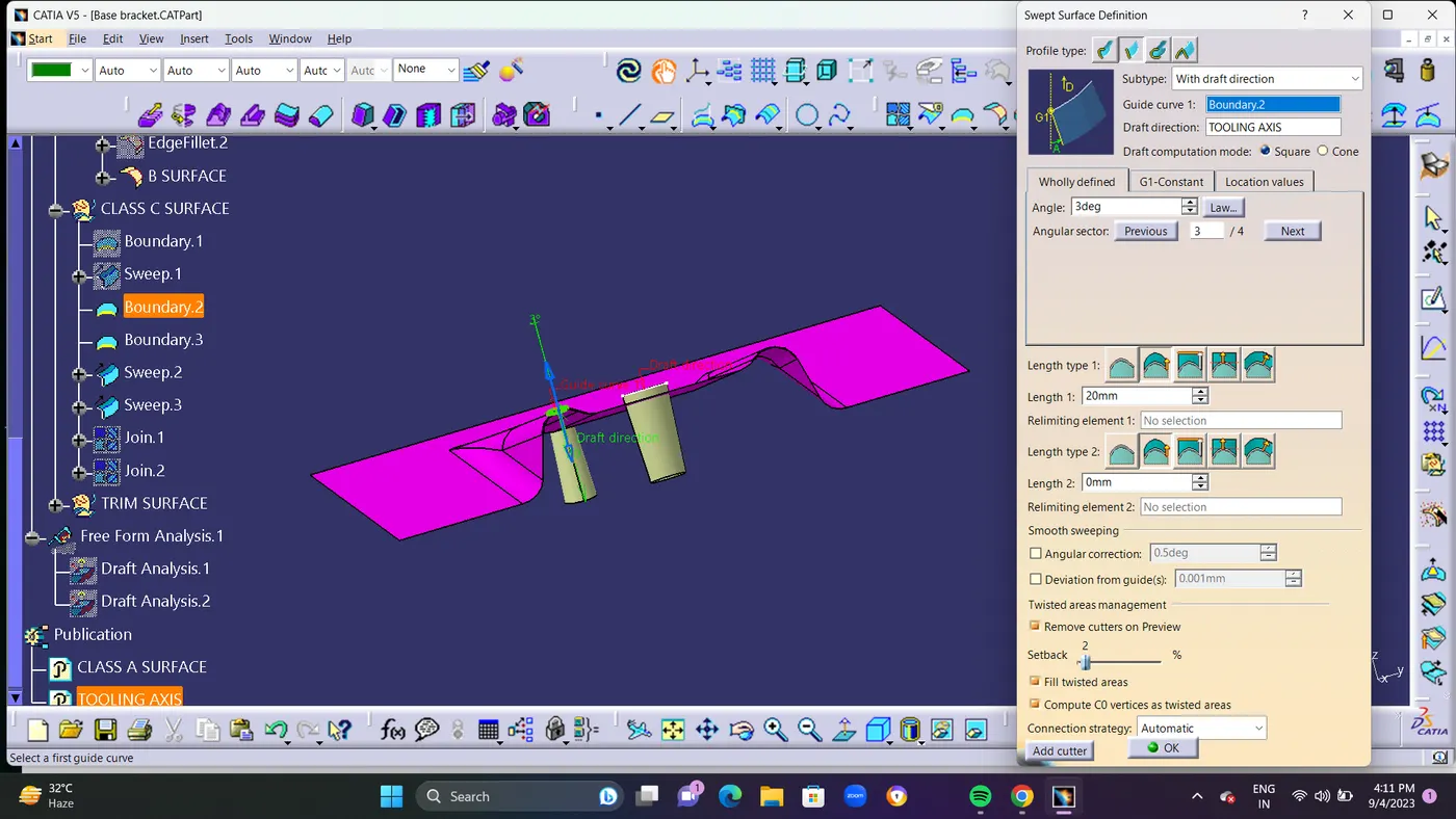
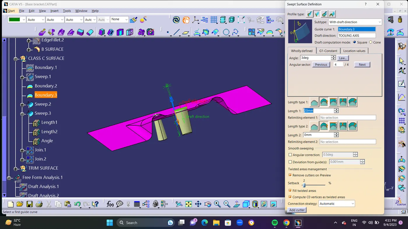
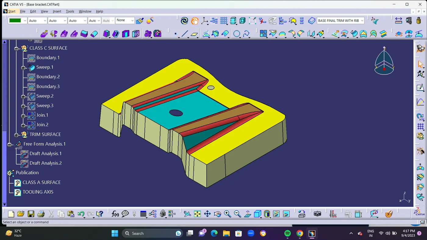
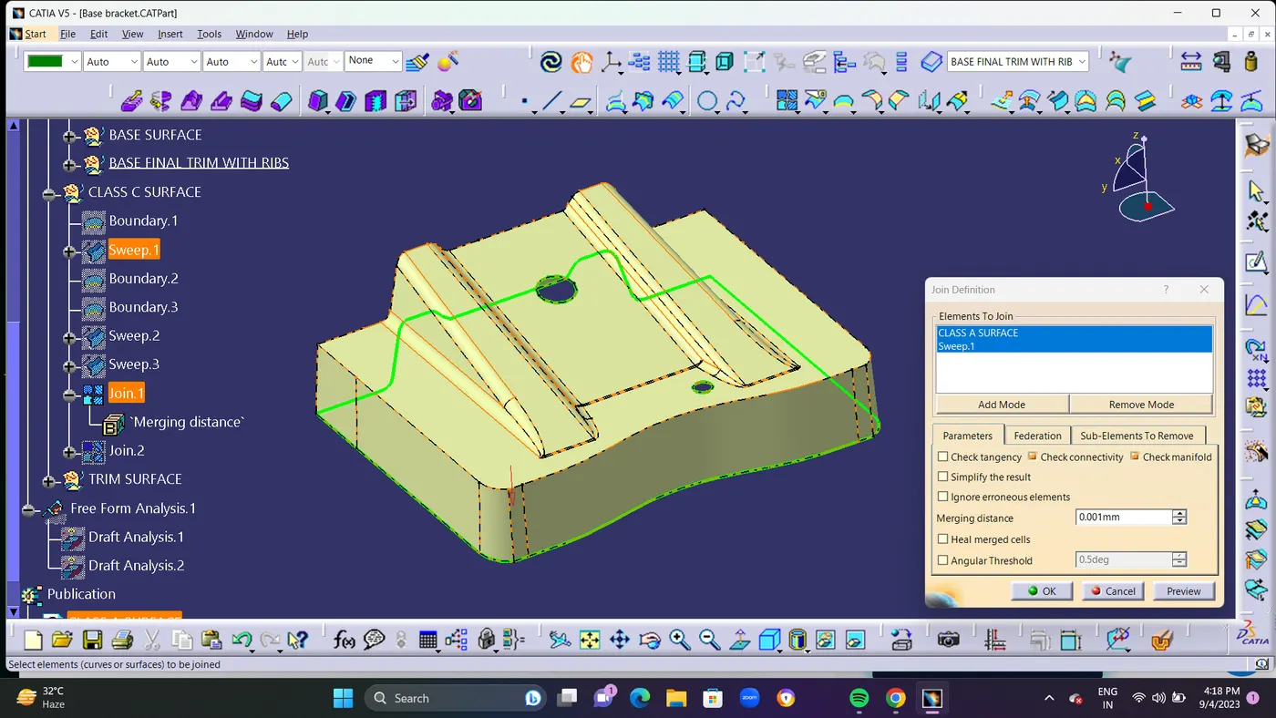
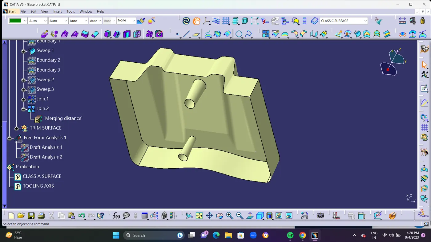
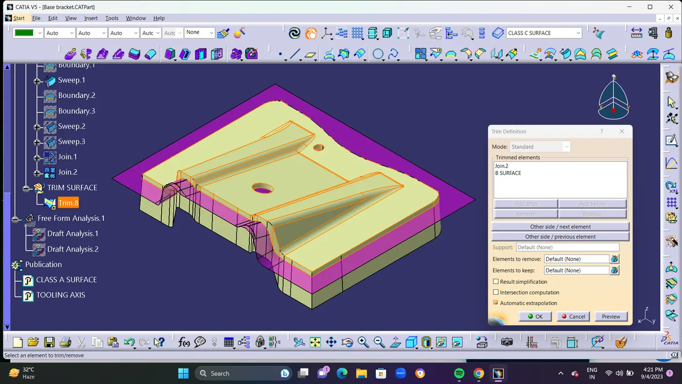
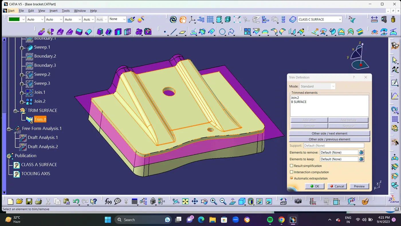
- STEP 11: Using JOIN Command Join Class A Surface and Class C Sweep Surface Together.and Join the two Hollow Surface with Class A Surface to make as single Join.and (FINAL TRIM) TRIM the Class A and C with Class B Surface to form an hollow gap 2.5mm in Between A and B Surface.By using Section Command you can see the gap.
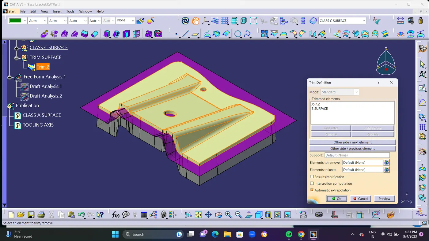
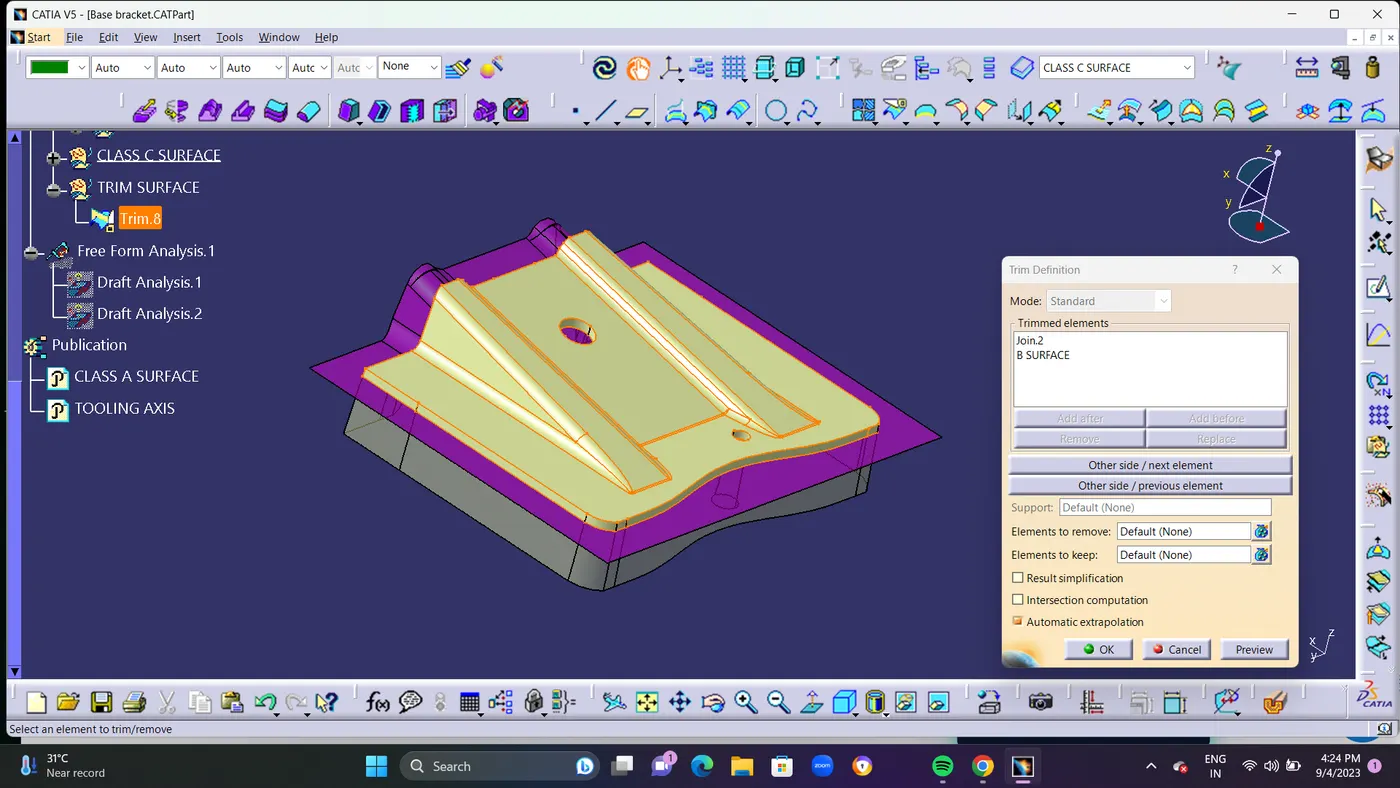
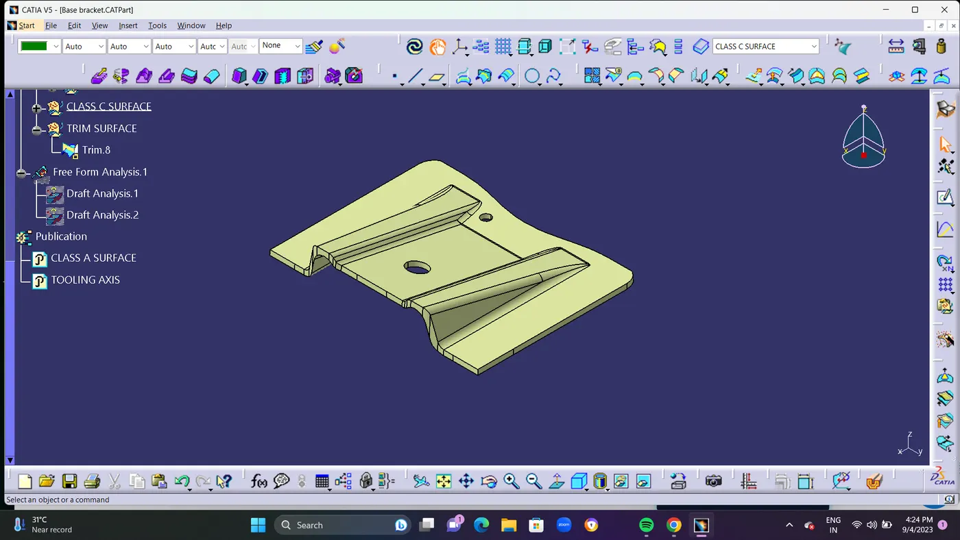
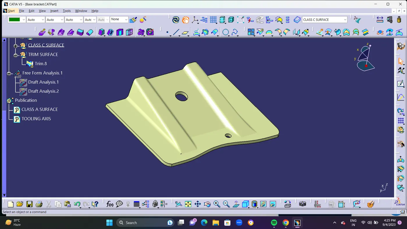
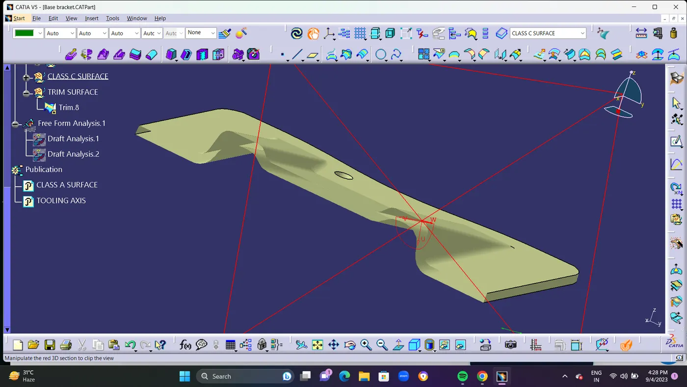
- STEP 12: And Finally Created Close Surface in PartBody By Using CLOSE SURFACE METHOD
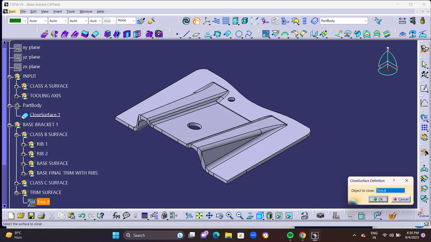
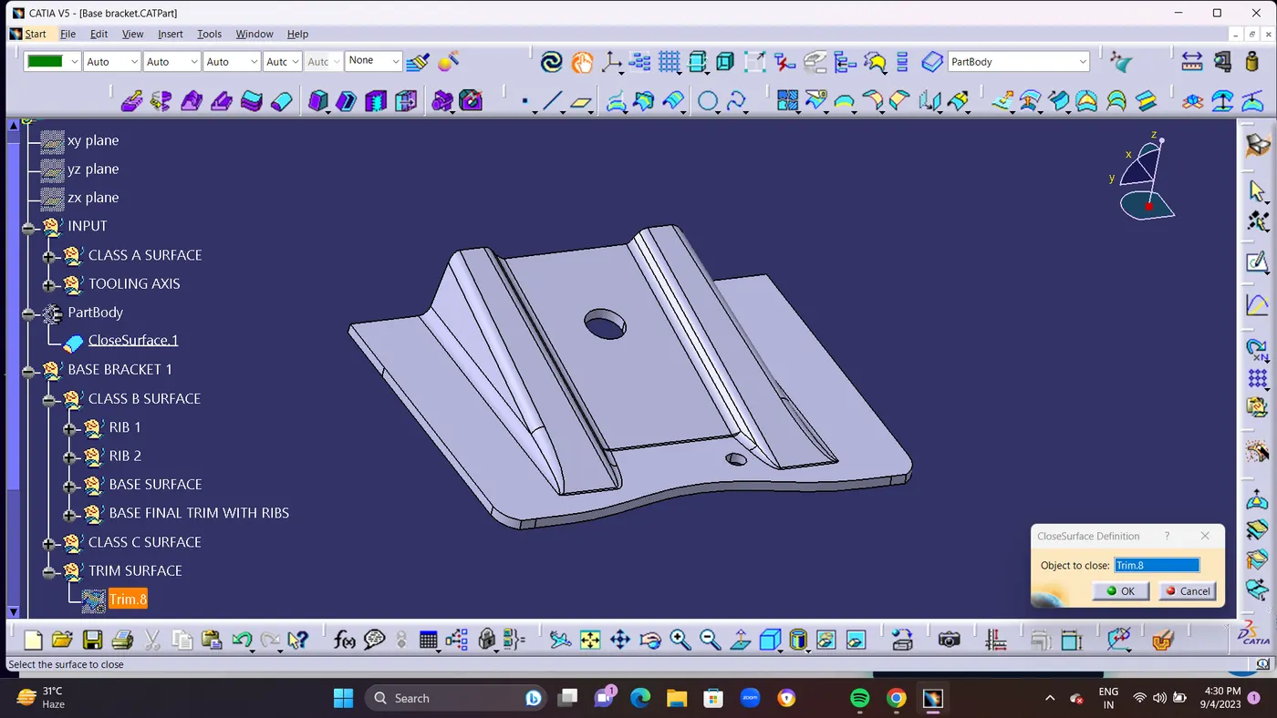
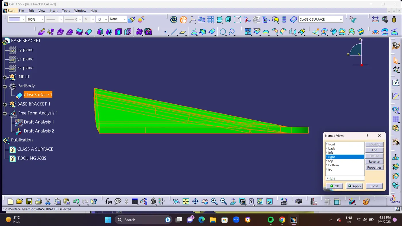
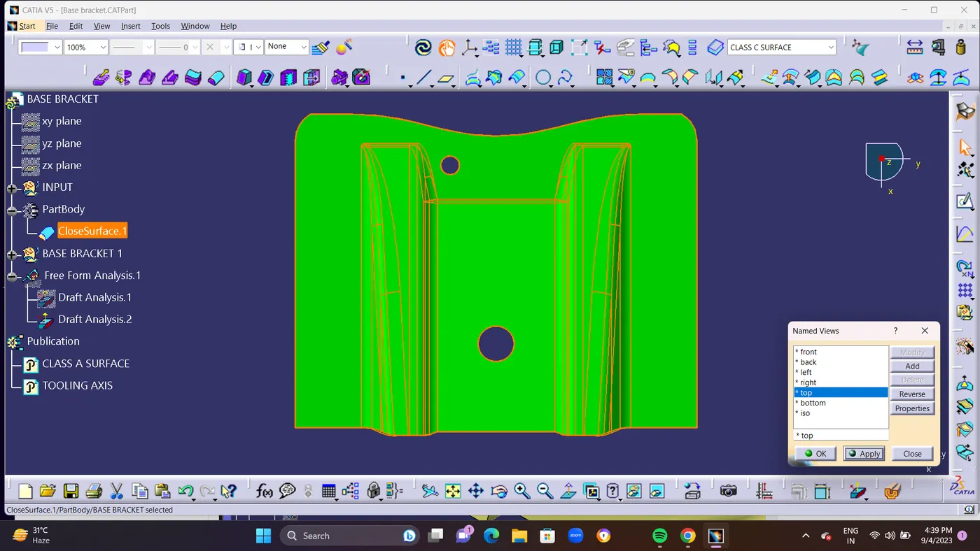
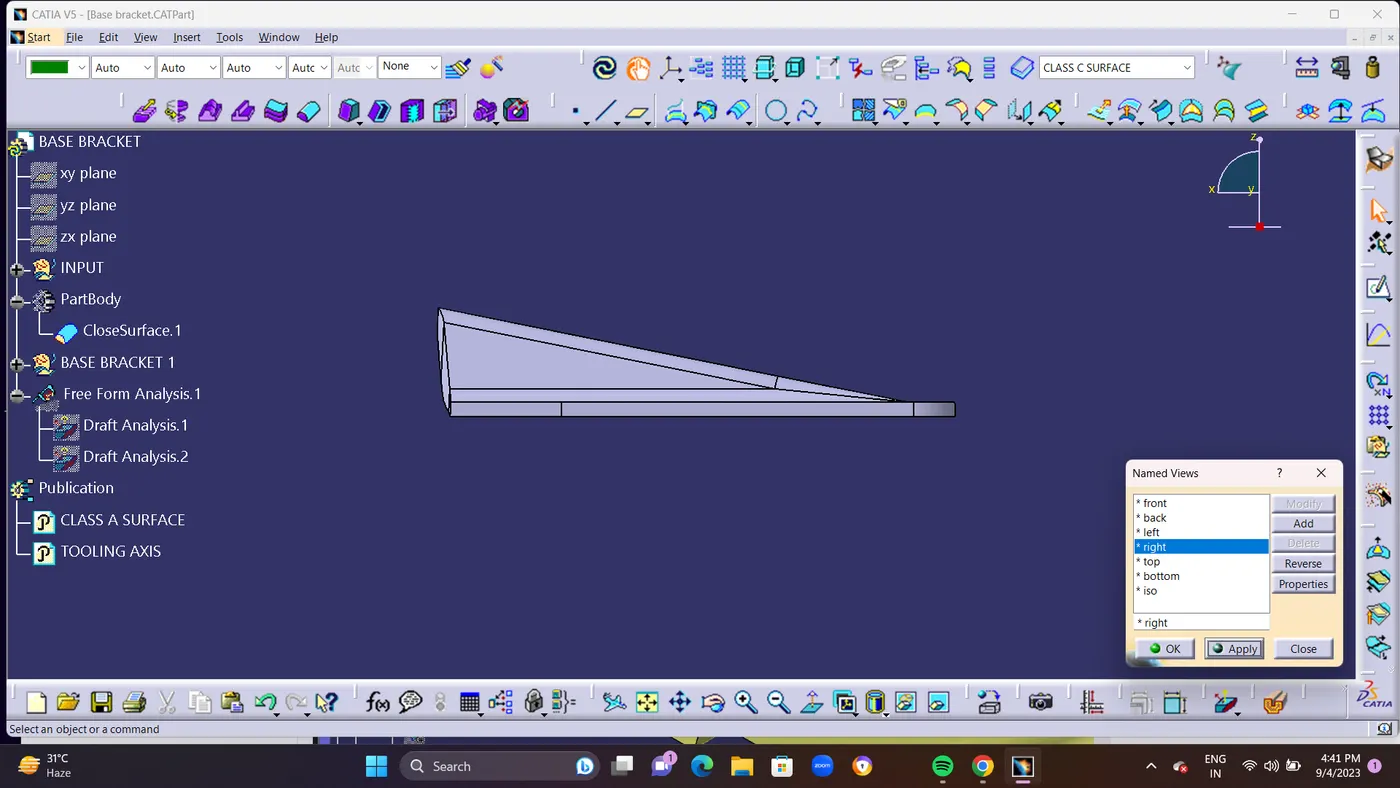
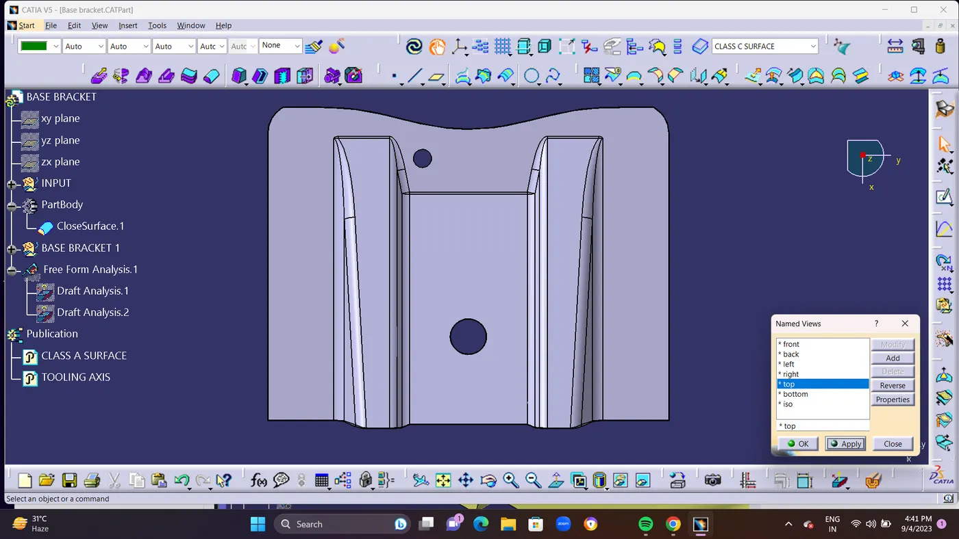
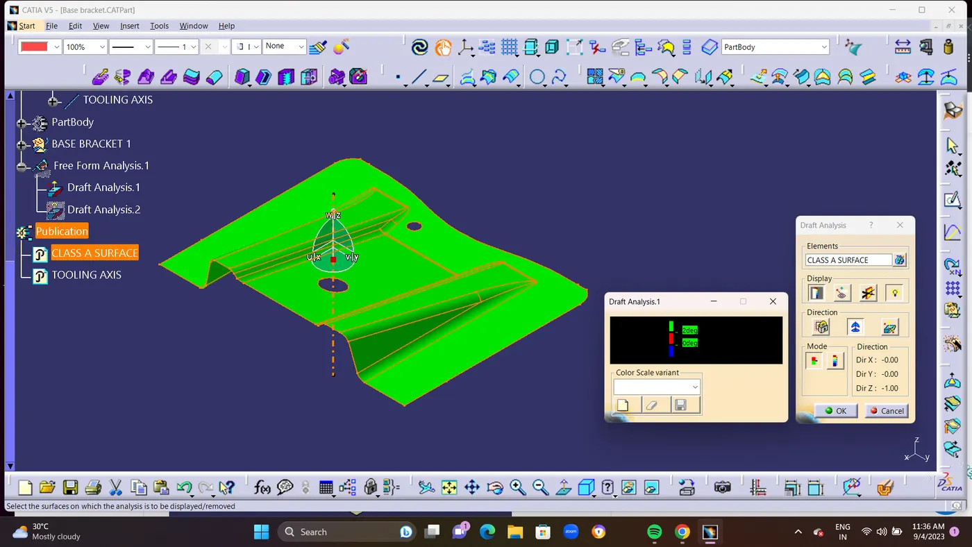
- STEP 13: After Creating CLOSE SURFACE DRAFT ANALYSIS METHOD is used.Draft analysis is required to check if a part has required draft or not. Draft is required so that a part can be ejected from its mould easily.Draft will be Maximum 3 Degree.But For me its failing at 2.7 Deg So i used to make it as 2.5 Deg As Maximum Level in Closed Surface Draft Analysis Method.Use MATERIAL MODE To Check Draft Analysis.Use Compass in Tooling AXIS while Drafting.
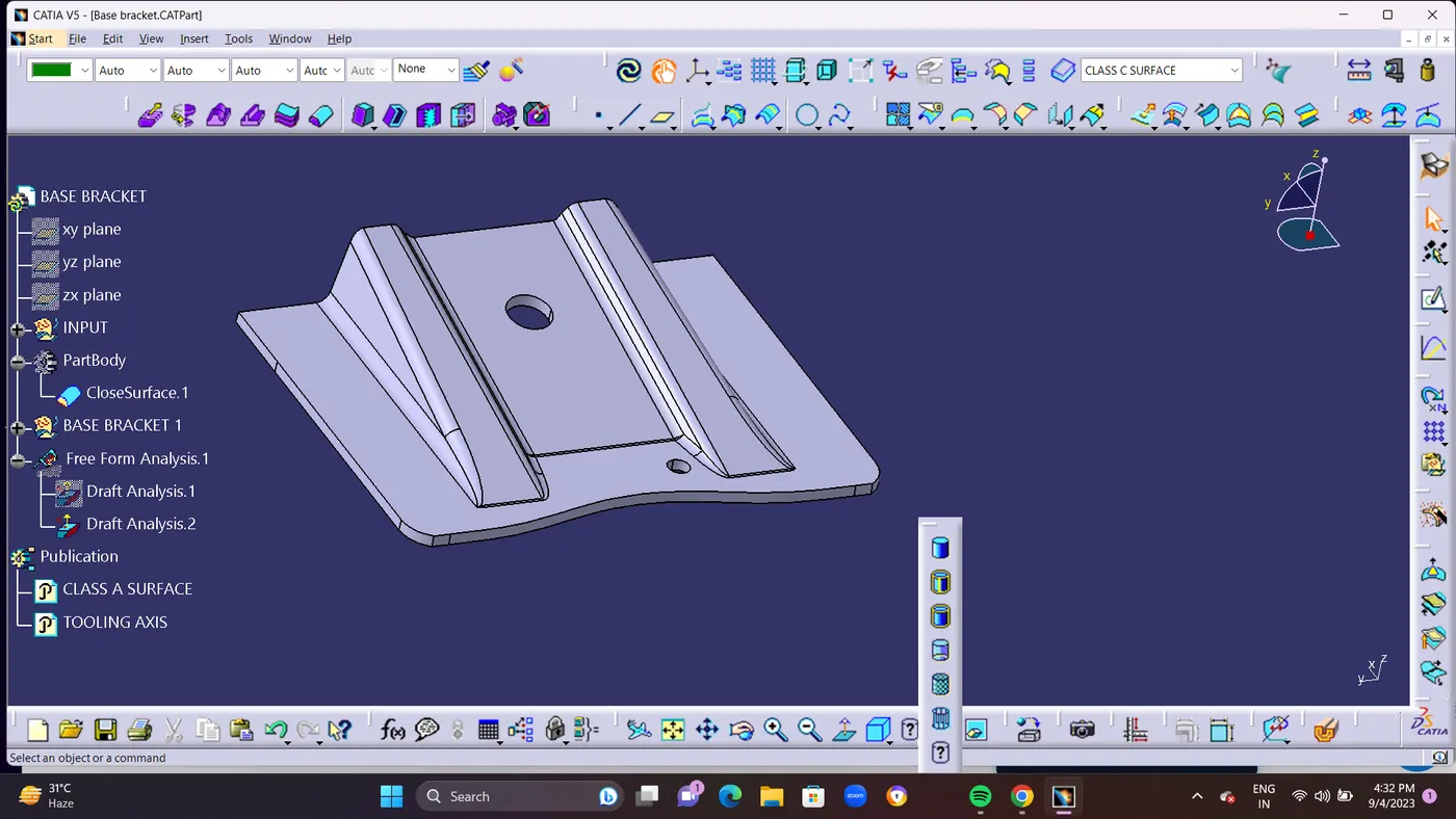
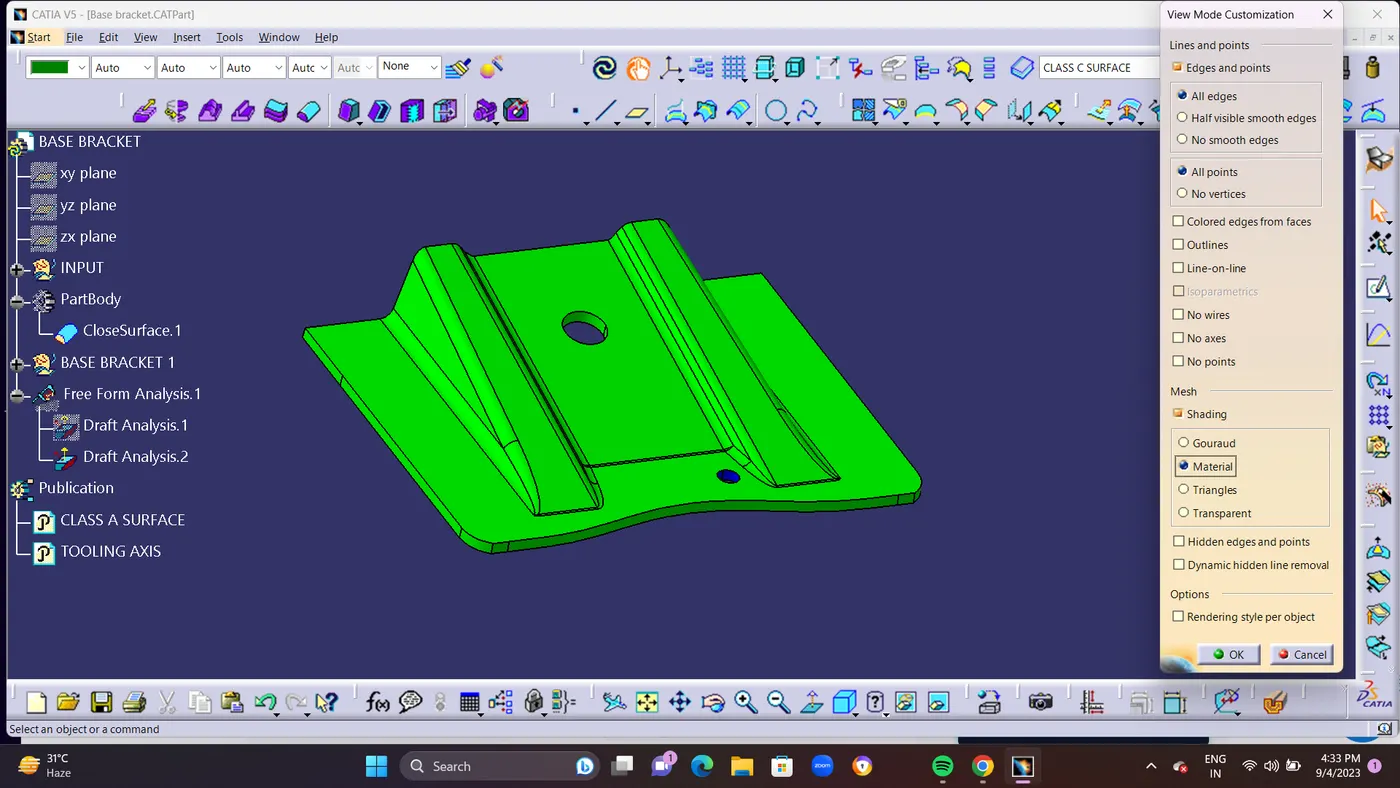
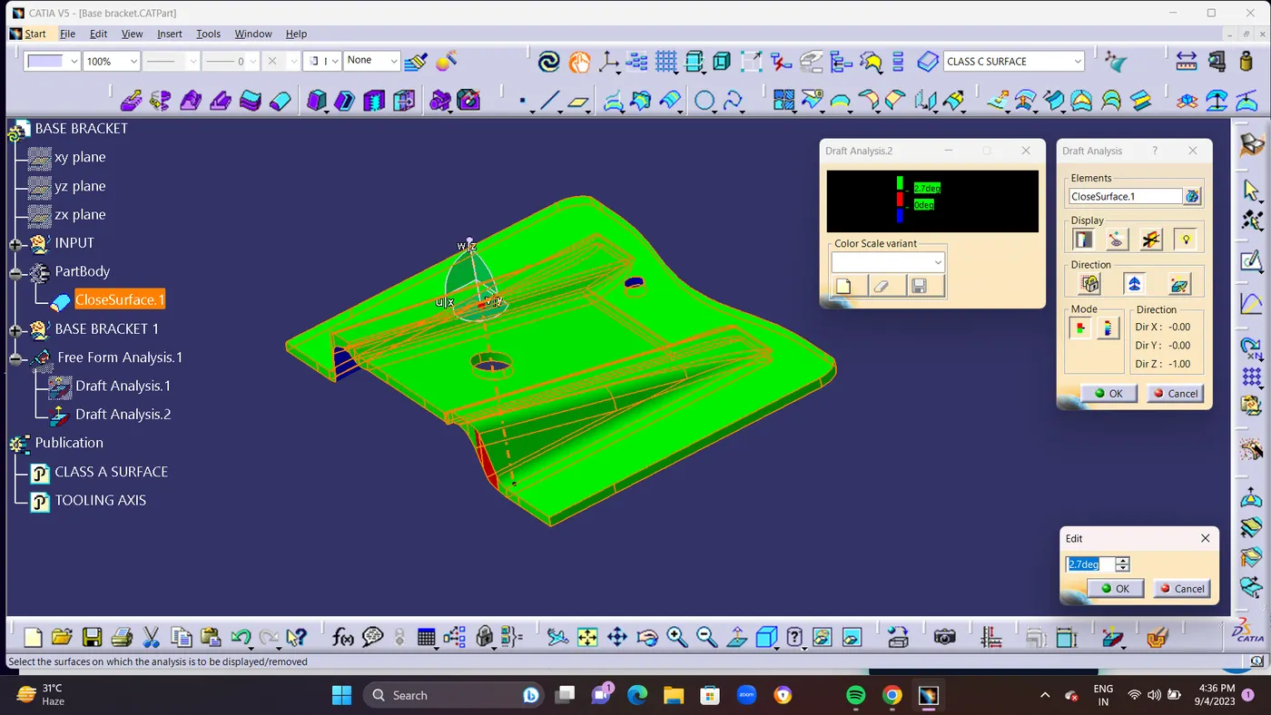
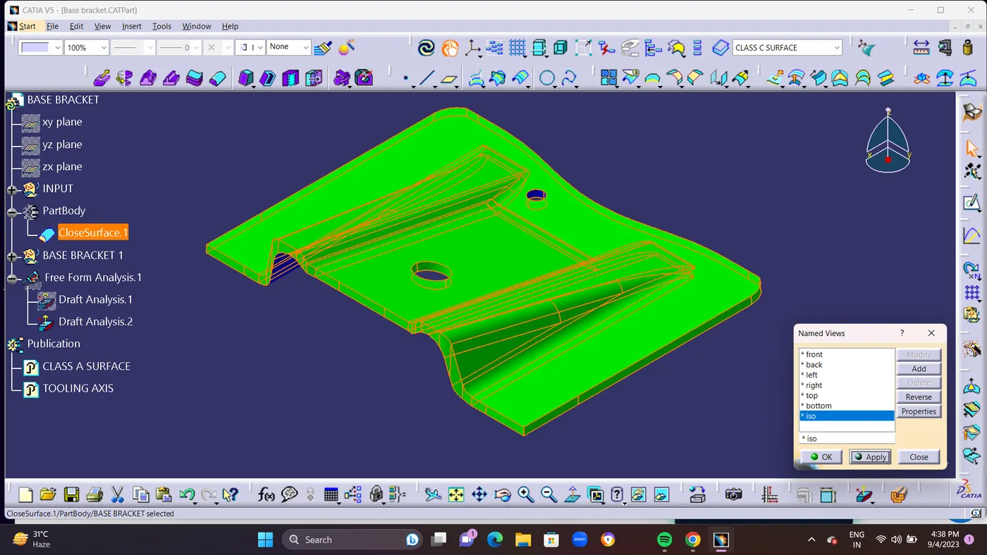
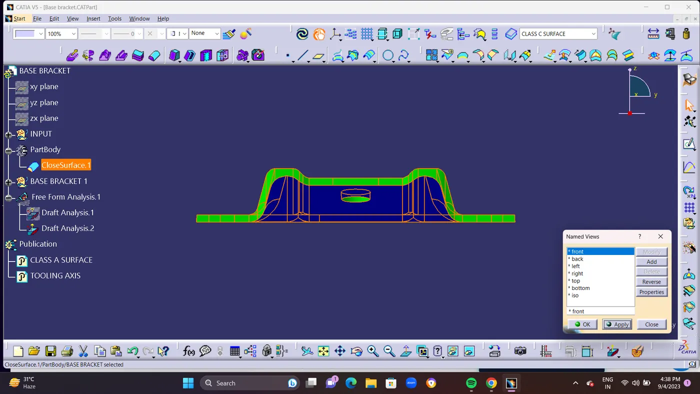
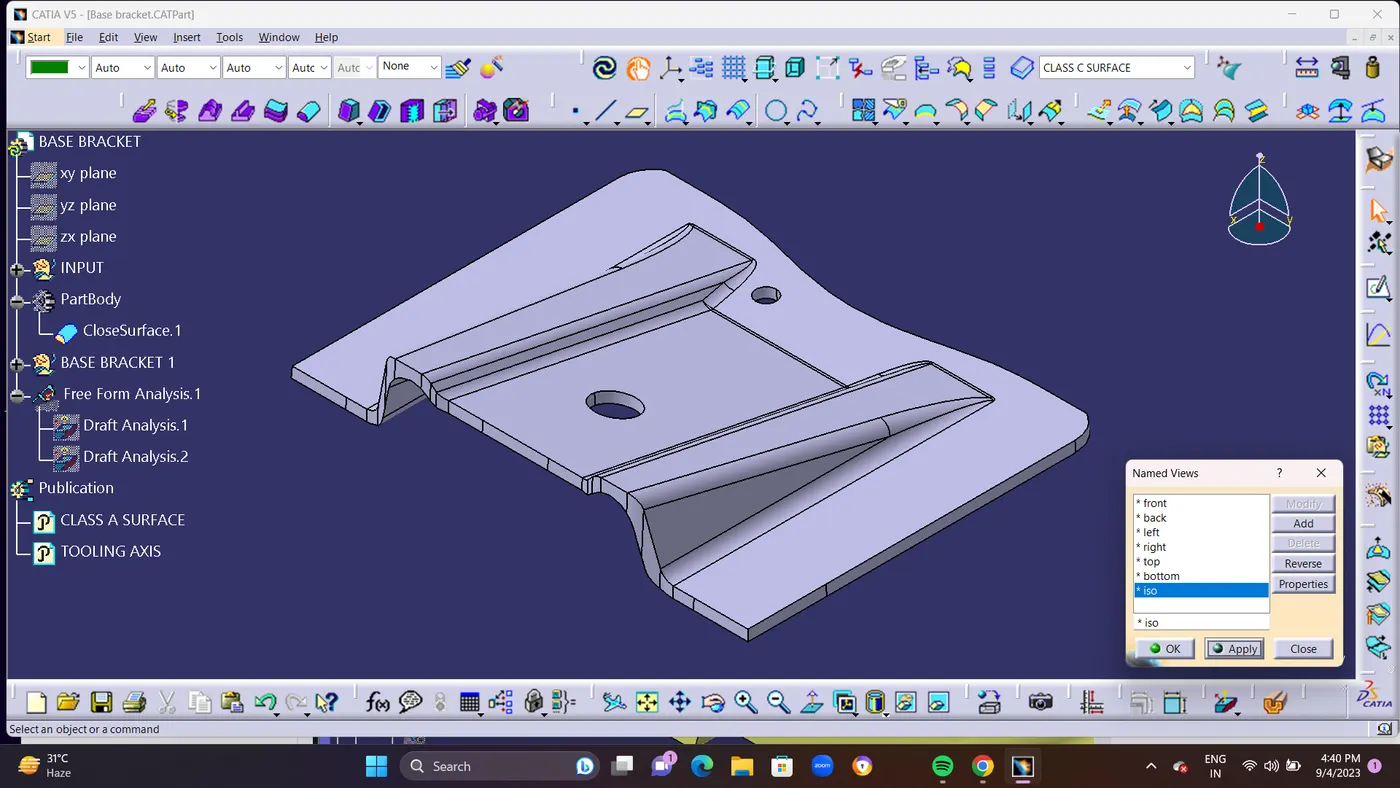
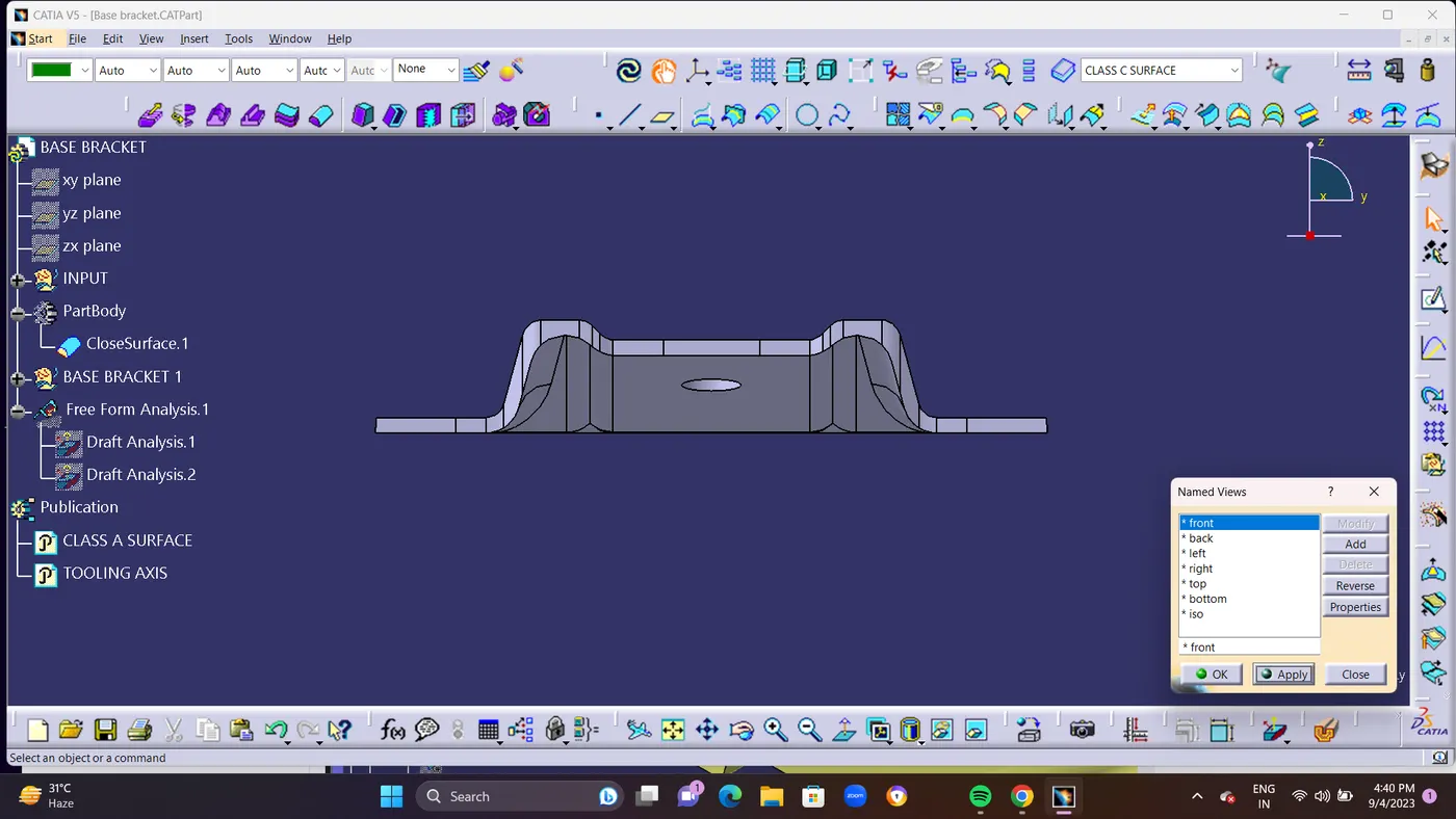
- STEP 14: In Draft Analysis If it shows Green Colour Surface. its Pass in Drafting.Suppose its shows in Red Colour Surface its Fails in Draft Analysis.and Finally ISO,FRONT,SIDE, and TOP View Should Be taken As ScreeenShots.