Week 9 - Challenge 3 - Bumper
AIM
Create the Bumper Plastic component by the given Class-A surface. To begin with, the tooling axis for the given Class-A Surface might be created meeting the requirements of the draft angle and at the end perform the Draft analysis on the model.
INTRODUCTION
- Many people think the purpose of bumper is to prevent lesser injury severity in a crash.
- The purpose of bumper is to reduce or prevent physical damage to the front and rear side of the vehicle in low speed crashes .
- By design, bumpers protect the hood, trunk, grille, fuel, exhaust, and cooling system.
- A bumper is a shield that is usually made of steel, aluminium, rubber, or plastic. It absorbs shocks from car accidents.
- Bumpers of most modern automobiles have been made of a combination of polycarbonate (pc)
and acrylonitrile butadiene styrene (ABS)
PROPERTIES OF ACRUYLONITRILE BUTADLIENE STYRENE
- <!--[endif]-->Good chemical resistance
- <!--[endif]-->Aging resistance
- <!--[endif]-->Easy processing
- <!--[endif]-->Low over all shrinkage
- <!--[endif]-->High dimensional accuracy
- <!--[endif]-->Colourable and printable
DESIGN METHODOLOGY
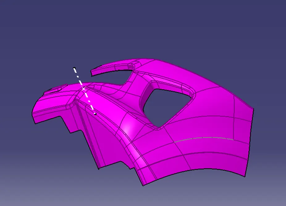
Skin data gathered from stylus team (CLASS A)
Class A: The class A surface is a stylus surface ,made by stylus team after creating the surface transfer
to part design engineer to create the part based on the requirement
In that first and foremost step after getting the surface from stylus team to check the connexity and
the gap between the surface .
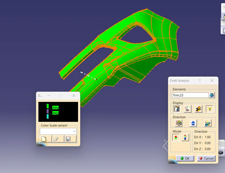
Tooling axis
In moulding part machine arrangement is given to open the mould along a direction which is known as tooling direction
In other words .mould is built from two separate halves and tooling direction basically defines the direction of mould pulls apart,
Tooling direction is known as primary direction
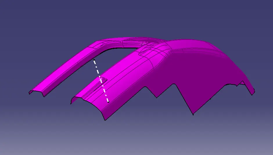
Creation of tooling axis using bisecting method .to create a line along the curve and the create a midpoint along the curve
and to make a bisecting line using the point ,the line as taking as a reference for tooling axis
CLASS B
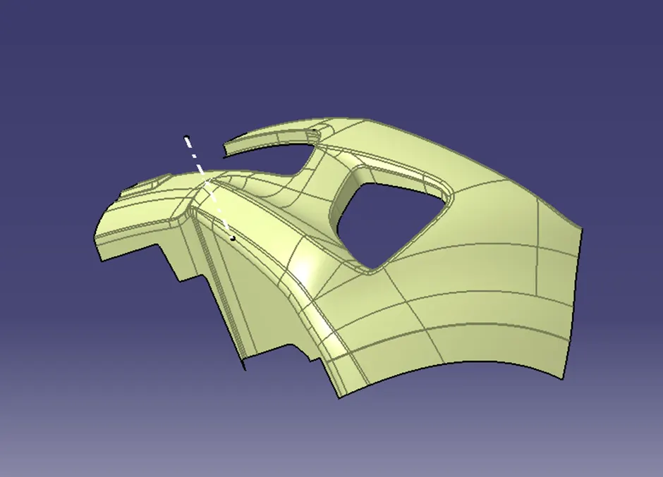
After creating the class A to generate a offset surface for creating the class B
By doing the process some fillets surface not to make offset
To refill the gap on the surface using extrapolate and trim command
Using of extrapolate command to expand the required boundary and to make intersection
By using trim command to remove the extra surface
For removing the unwanted surface by using the join command ,by removing the sub elements for exemption
for connexity error
After creating the surface to remove the sharp edges using the edge fillet
CLASS C
Before creating the class c surface to check all the boundary of the surface is parallel or perpendicular to the surface
If the surface is parallel to the tooling axis to create a c surface along the reference surface ,otherwise the surface
is perpendicular to the surface to create a surface using the draft direction
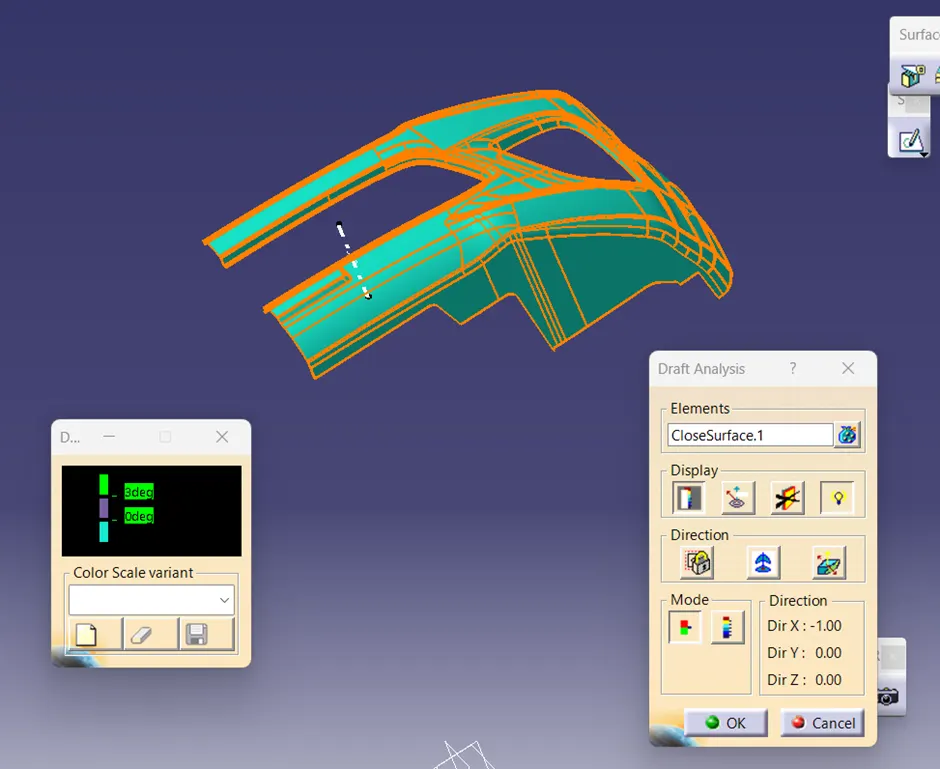
For creating a c surface as a reference as a tooling direction the draft angle as 3 degree and to select outwards
To join the class A and Class c surface using the trim command
Final surface
To trim the final surface and class B surface using the trim command
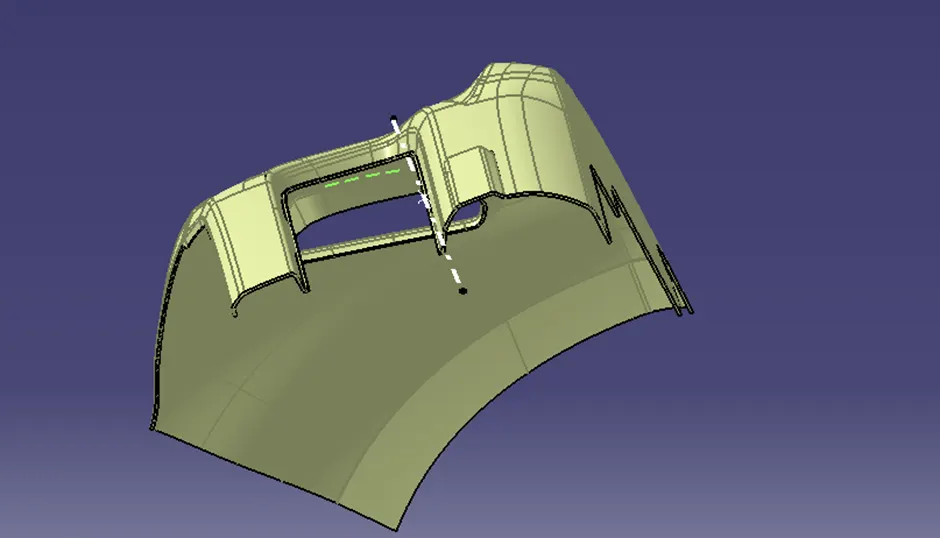
CLOSURE SURFACE
To generate a solid surface using generating part design by closure surface command
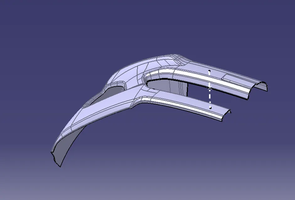
Draft analysis
Multi view
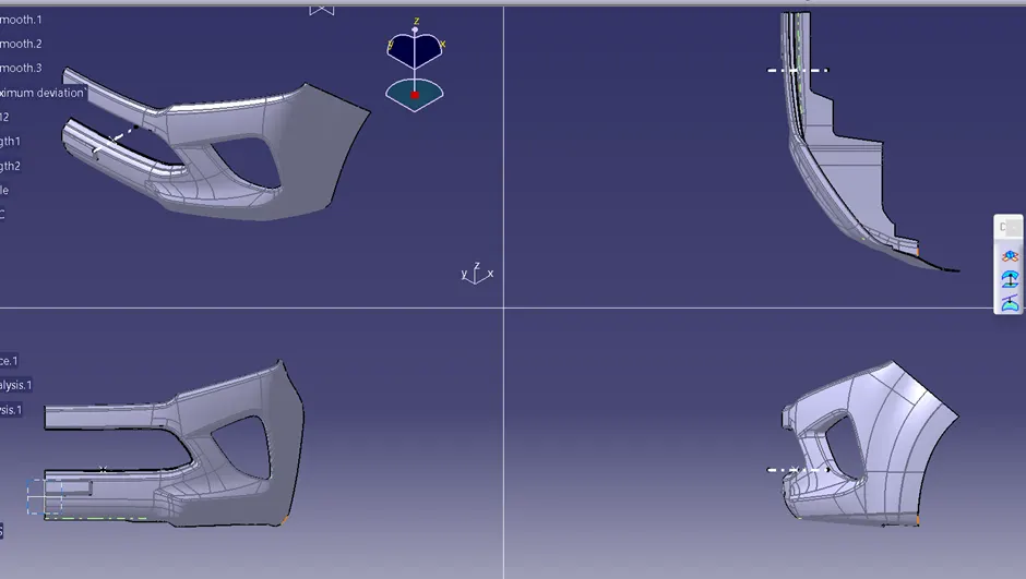
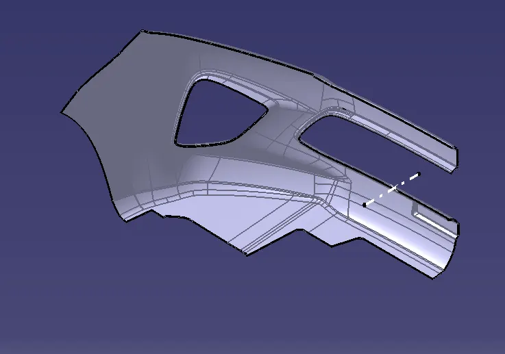
ISOMETRIC VIEW
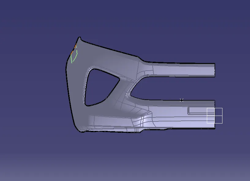
FRONT VIEW
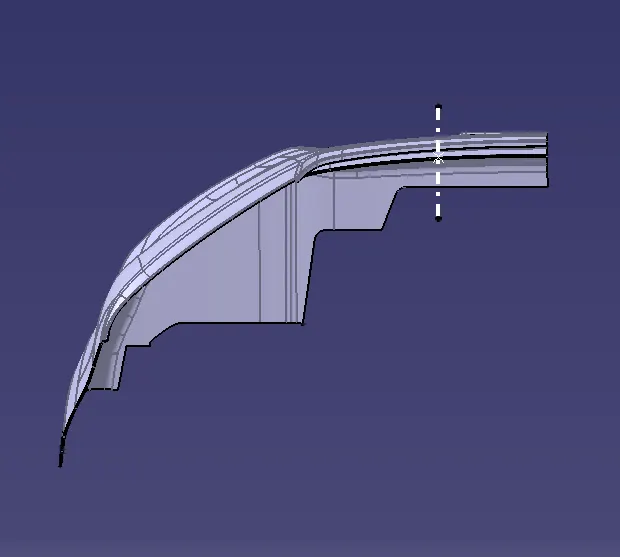
TOP VIEW
Result
Finally, the bumper closure surface and also front view ,isometric view ,top view has been created ,
also draft analysis has been created