Fender Design - Wheel Arch Challenge
Calculate the wheel arch Gap at required points and check whether the car passes the European Standard
AIM
- To study about the fender wheel arch and types
- Analysis gap between the fender arch and the wheel
- Conclusion
FENDER
- Fender is a part of an automobile, motorcycle or other vehicle body that frames a wheel well (the fender underside).
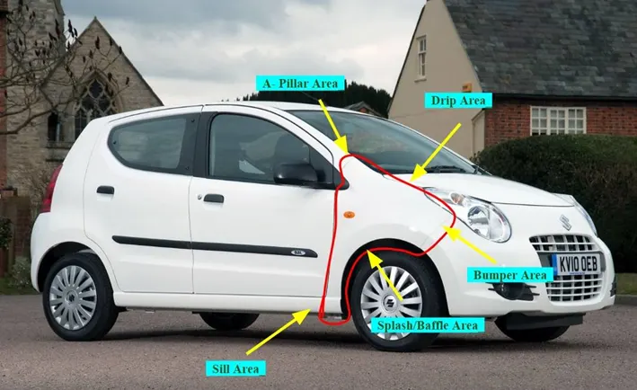
- Its primary purpose is to prevent sand, mud, rocks, liquids and other road spray from being thrown into the air by the rotating tire. Fenders are typically rigid and can be damaged by contact with the road surface.
WHEEL ARCH
- The wheel arch is an arch-shaped cavity in the body of a vehicle, which houses a wheel. It has two important functions. It serves for the safety of pedestrians and other cars because the wheel is situated in the body of a vehicle.
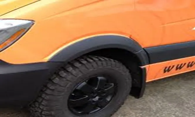
- The second function is to protect the car from the sticky materials, such as mud, may adhere to the smooth outer tire surface, while smooth loose objects, such as stones, can become temporarily embedded in the tread grooves as the tire rolls over the ground.
- These materials can be ejected from the surface of the tire at high velocity as the tire imparts kinetic energy to the attached objects. For a vehicle moving forward, the top of the tire is rotating upward and forward and can throw objects into the air at other vehicles or pedestrians in front of the vehicle.
TYPES OF FENDER WHEEL ARCH REGULATION
- JAPAN STANDARD
- EUROPEAN STANDARD
- US REGULATION STANDARD
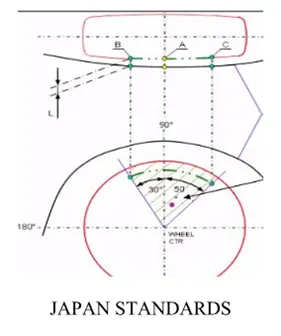
JAPAN REGULATION
The clearance value will be more than the 5mm based on reference point 30 degrees at forward and 50 degrees at backward from the central vertical line.
EUROPEAN REGULATION
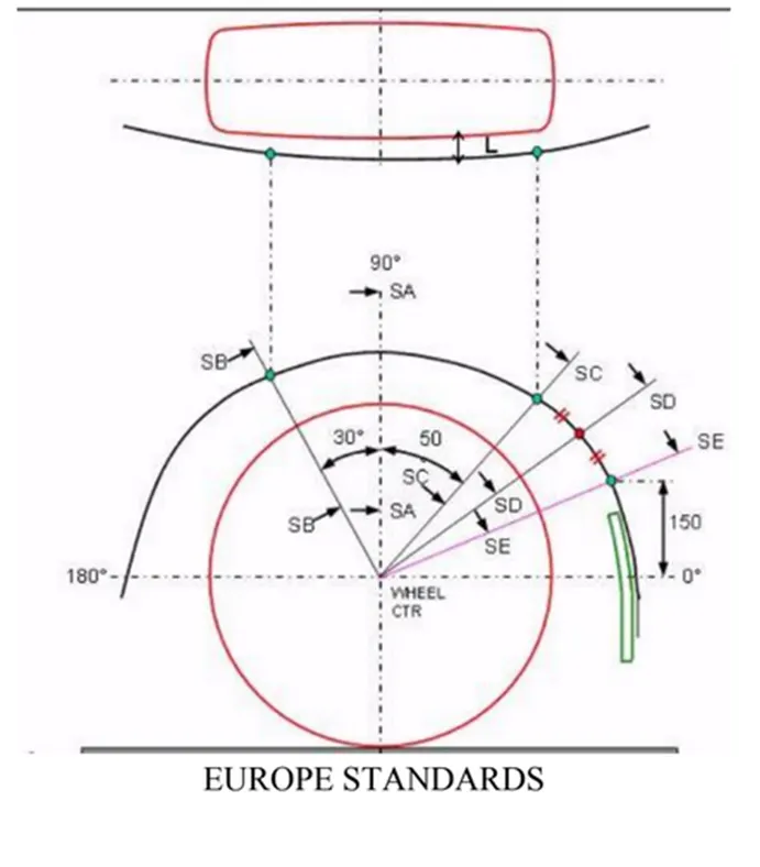
The clearance value will be more than 10mm based on reference point created 30 degrees at forward and 50 degrees at backward and line 150mm above X-axis the point intersect the curve and line
US REGULATION
Make clearance check details on all position from -10 to 180 degrees. All values must be greater than 5mm.The Clearance Value will more than 5mm at line 30 degree forward and 50 degree backward from central vertical axis.
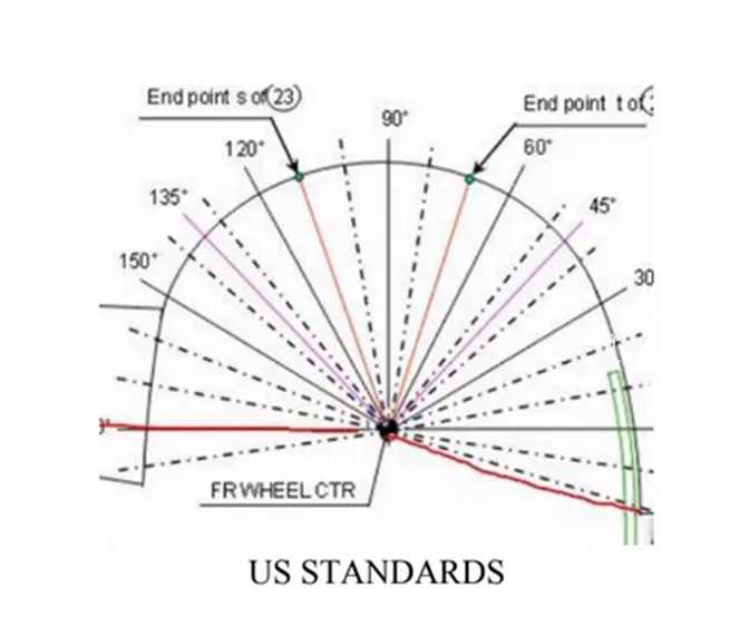
THE FOLLOWING STEP HAS BEEN FOLLOWED TO ANALYSIS THE GAP BETWEEN THE FENDER ARCH WHEEL AND TYRE
- STEP-1
Create a datum plane along the surface of tyre take as a reference
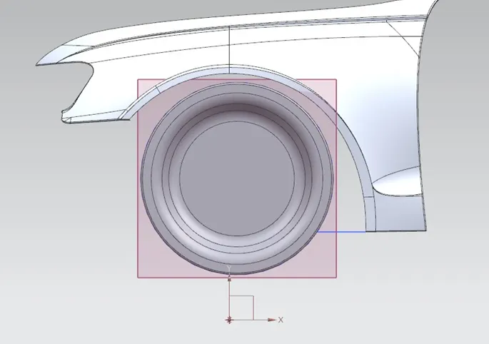
- STEP-2
Draw the horizontal and vertical line based on centre of the circle
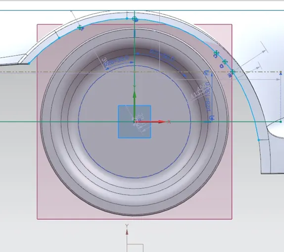
- STEP-3
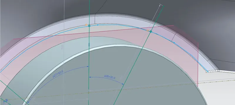
Draw the inclined line as an angle of 30 degree and 50 degrees take reference as a vertical line forward and backward
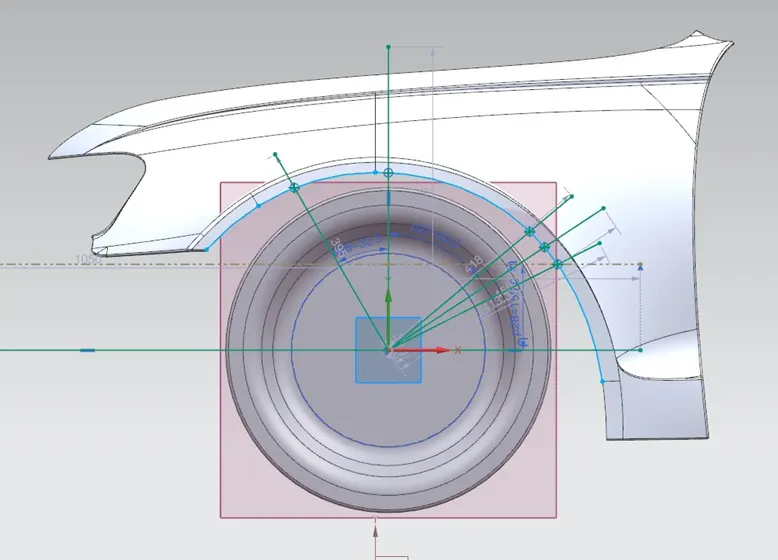
- STEP-4
Offset of horizontal line from the distance of 150mm from the line and also make offset curve from fender curve portion, both of them meet at a point to make a point using an intersection point

- STEP-5
To project the point along both the direction using the project curve
- STEP-6
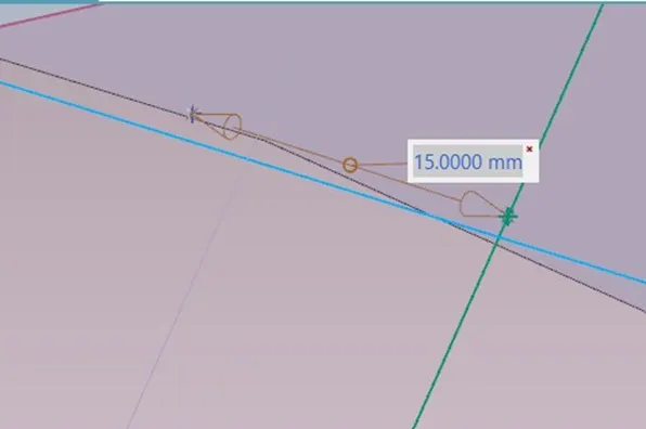
Measure the point lies between A and the respective project point
- STEP-7
Measure the point lies between B and the respective project point
- STEP-8
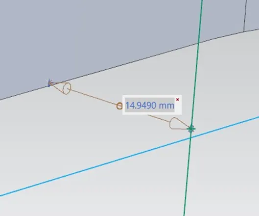
Measure the point lies between C and the respective project point
- STEP-9
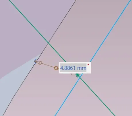
Measure the point lies between D and the respective project point
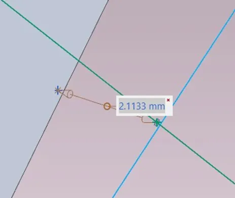
- STEP-10
Measure the point lies between E and the respective project point
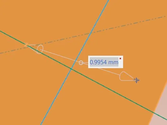
CONCLUSION
Based on the above case study some of the intersecting point to reference point not satisfy the European regulation standard So, the above fender wheel arch design is considered as a Fail