Week 9 - Challenge 3 - Bumper
Aim :- To Create the Bumper Plastic component through the given Class-A surface. To begin with, the tooling axis for the given Class-A Surface should be created meeting the requirements of the draft angle and at the end perform the Draft analysis on the model. Take the Thickness of the component to be 3 mm.
BUMPER :- A bumper is a structure attached to or integrated with the front and rear ends of a motor vehicle, to absorb impact in a minor collision, ideally minimizing repair costs. Stiff metal bumpers appeared on automobiles as early as 1904 that had a mainly ornamental function. Numerous developments, improvements in materials and technologies, as well as greater focus on functionality for protecting vehicle components and improving safety have changed bumpers over the years. Bumpers ideally minimize height mismatches between vehicles and protect pedestrians from injury. Regulatory measures have been enacted to reduce vehicle repair costs and, more recently, impact on pedestrians.
Class A Surface :- In automotive design application Class A Surfaces are created on all visible exterior surfaces (ex; body panels, bumper, grill, lights etc.) and all visible surfaces of see-touch & feel parts in interior (ex: Dashboard, seats, door pads etc.). This can also include beauty covers in the engine compartment, mud flaps, trunk panels and carpeting. This surface has 0 mm thickness.
Given Class A surface
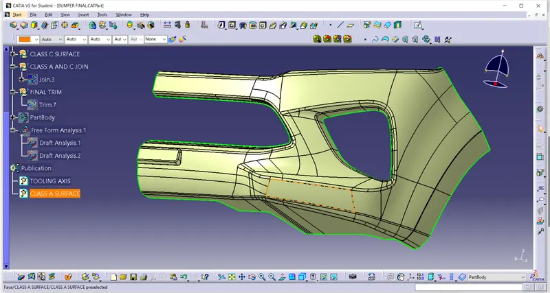
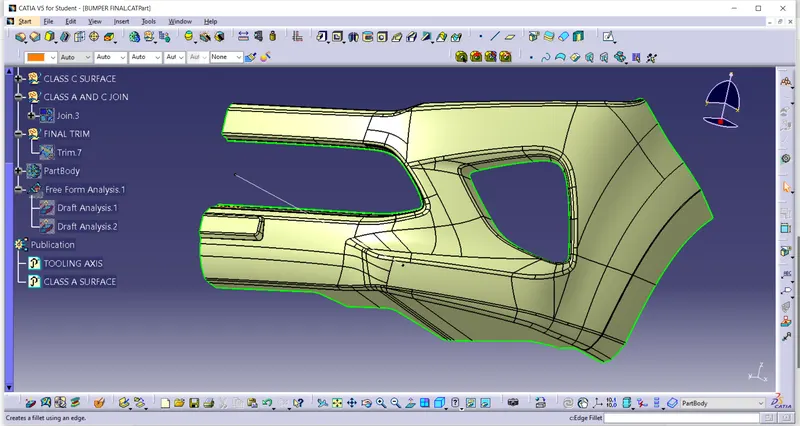
Tooling Axis :- Tooling axis or tooling direction is main consideration for plastic part and mold parts because it defines movement of mold part and possibility of plastic part to come-out from mold part (Core and Cavity). In Molding machine arrangement is given to open the mold along a direction which is known as Tooling Direction. The mold is built from two separate halves (Core and Cavity) and tooling direction basically define the direction of mold pulls apart. Tooling direction is known as primary direction.
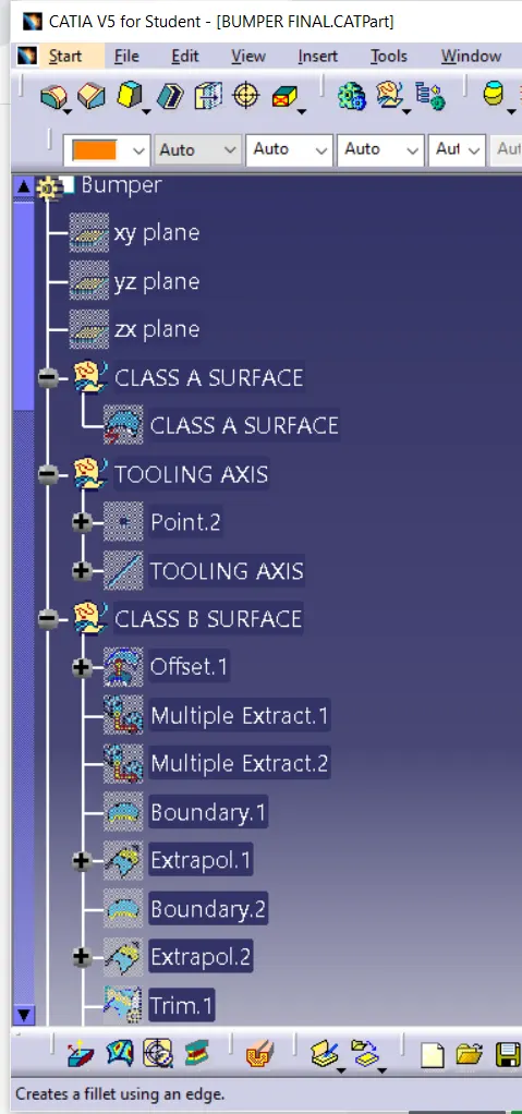
Here I have created a tooling axis. First of all I extract a base surface and create a mid pont on it. And then I create a line through this point with perpendicular to base surface. And then I performed draft analysis ans I saw every thing is ok. Then finally it is my tooling axis.
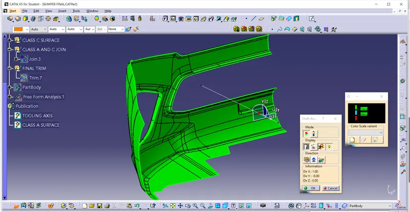
Draft Analysis :-The Draft Analysis is a command enables you to detect if the part you drafted will be easily removed. This type of analysis is performed based on colour ranges identifying zones on the analysed element where the deviation from the draft direction at any point, corresponds to specified values.
Draft analysis is done after determining the tooling axis, draft analysis is used to check whether the minimum draft (3 degrees) is maintained or not.
The Draft Analysis allows the user to easily analyze a part for proper draft angle. A Draft Angle describes the amount of taper for molded or cast parts perpendicular to the parting line. Draft Analysis is applicable for 3D part models. To create a draft analysis for any 3D part file, the user needs to select part/surface select the pull direction. You can change the pull direction.
Class B Surface :- The surface which is back side of Class A surface is called Class B Surface. Mostly it not visible. It is created with the help of Class A surface with some distance (thickness) like 2mm, 3mm etc.Here I created Class B Surface on 3mm from Class A Surface.
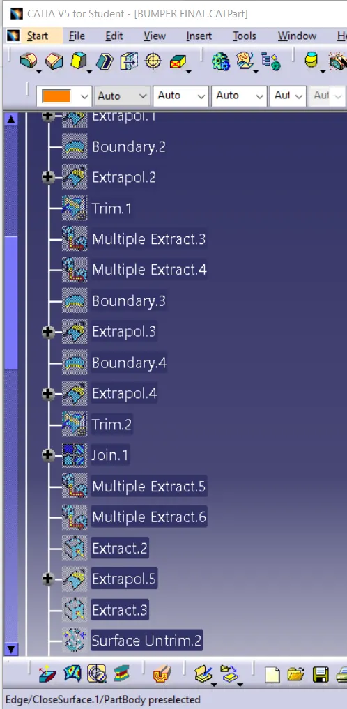
Class B surface, I will use the following command:
- Boundary: Select the required boundary if required.
- Extraction: In this, no boundary is required, so go to extract the flat surface of class A.
- Untrim: After extrapolating, Untrim those surfaces.
- Extrapolate: extrapolate those surfaces by as per required .
- Trim: trim those extrapolate surfaces to get the desired surface.
there is second method also used for Class B surface
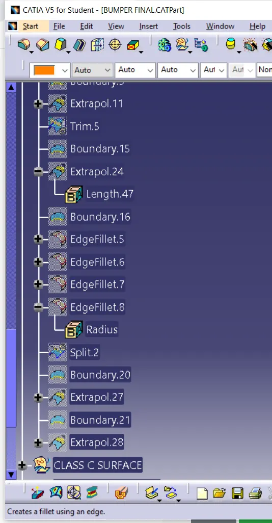
Join command also used for creating Class B surface .
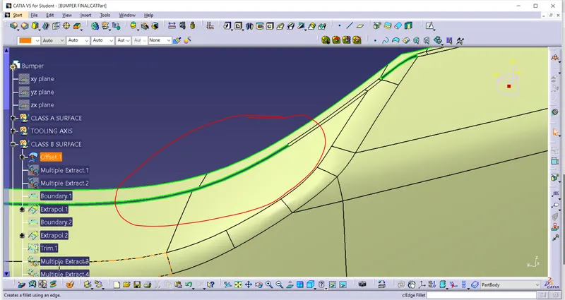
After used of proper command we fill all gaps and paches in between the Class B surface .Final Class B surface in below Image .
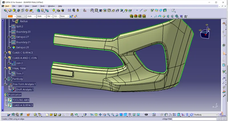
CLASS C SURFACE:-Surface that joins class-A and class-B surfaces is class-C surface. Class C is often specified for interior surfaces not readily visible, surfaces that will be covered by another part when assembledSince it is a complex class-A surface, we cannot simply create the class-A boundary curve and sweep it at one shot. Hence, we need to create smaller curves using multi-extract command and then create sweep of 90 degree with reference to the surface option. sweeps at the midportion of the bumper should have a 93 degree value to pass the draft analysis.
The Class C surface is the back side of a part of a surface that is permanently covered by another part.With the help of join and trim feature I have created a closed surface body.
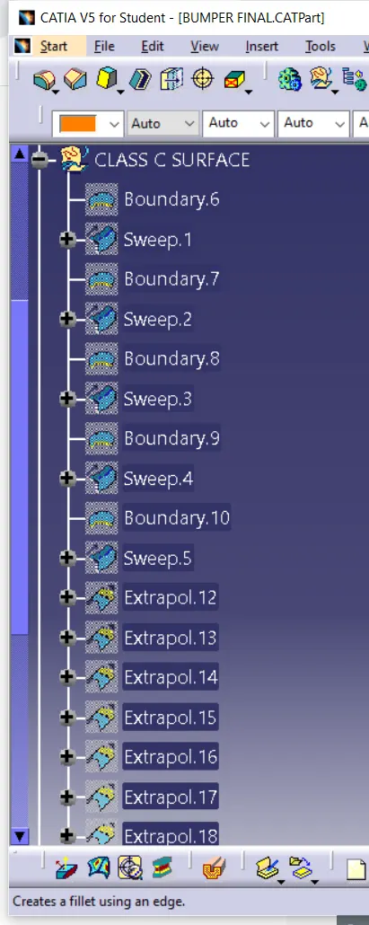
Class C surface generally connects the Class-B surface to the Class A surface.Referring to the below pic, Class-C Surface is shown.for creating a Class -C surface used the following command:
- Boundary: pick the boundary for the next operation.
- Swept: swept the selected boundary .
- Extrapolate: surface can't join properly, so I used to extrapolate those surfaces.
- Trim: trim those extrapolate surfaces and get a required surface.
- Join: now join those surfaces with each other and form a single surface.
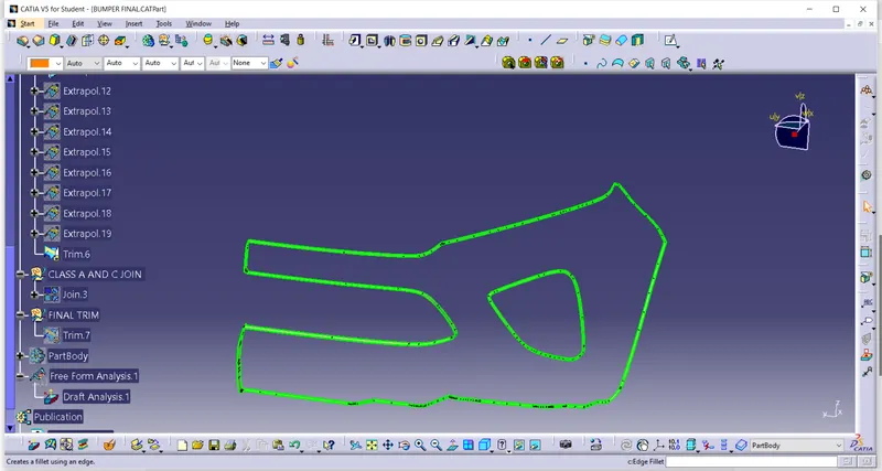
After Class A surface and Class C surface join .
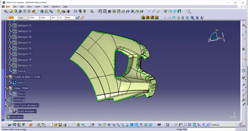
after join all the surface we did a final trim of all surface .
Final Trim :-
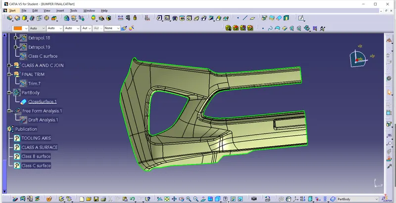
Now the class – A and Class- C surfaces were joined together by removing the gaps in-between them with the help of extrapolation(tangent continuity) and Trim surface.Then the exact surface of the bumper was trimmed from the above-resulted trim surface with the class-B surface.Then, by defining the part body by using the Closed Surface command in Part Design, the component's solid body is created.
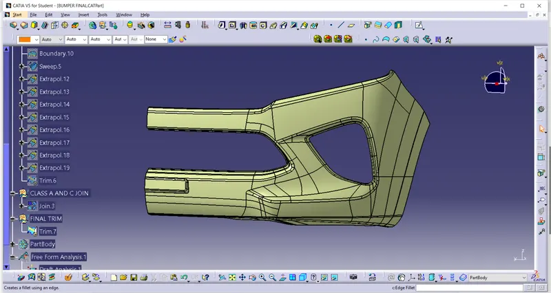
Solid Modal :- After trimming and joining all the three Class A, B and C Surfaces, the final solid model is created in the part body using the Close Surface tool in the Part Design workbench. This is the required solid component
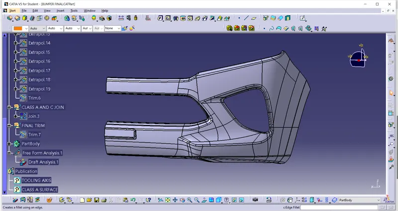
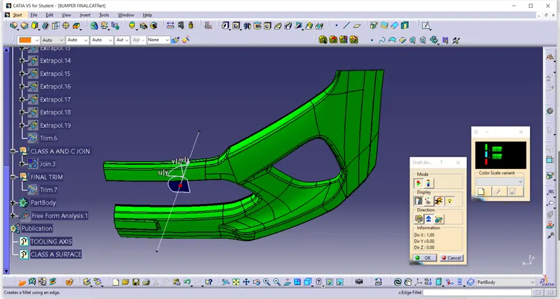
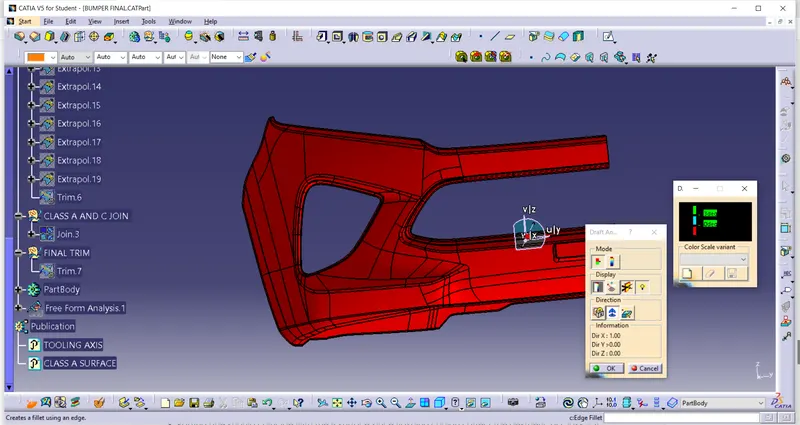
DRAFT ANALYSIS:- First the class – A surface is checked before creating the Class –B&C surface and finally the solid body must be analysed. Both can be done by following the below procedures.By changing the view mode to custom view parameters – Material mode then the feature draft analysis is enabled.Then the compass was activated and placed with the tooling axis by dragging the red pointer and then locked it.Then, by selecting the quick analysis mode, the nominal value will be 3 degrees and checked for the component's draft angle.The green colour area shows that it satisfies the 3-degree draft angle. If not satisfied then by using the Running point tool the area is measured and then altered to get a successful draft for the created tooling direction.
DESIGN CONSIDERATION:-
- Class – A surface should be aesthetically smooth and good.
- Class – B surface should have all the supporting features like ribs.
- Parting Line should coincide with the B surface since flashing couldn’t affect the aesthetic of Class – A.
- Class – C surface should also pass the draft analysis.
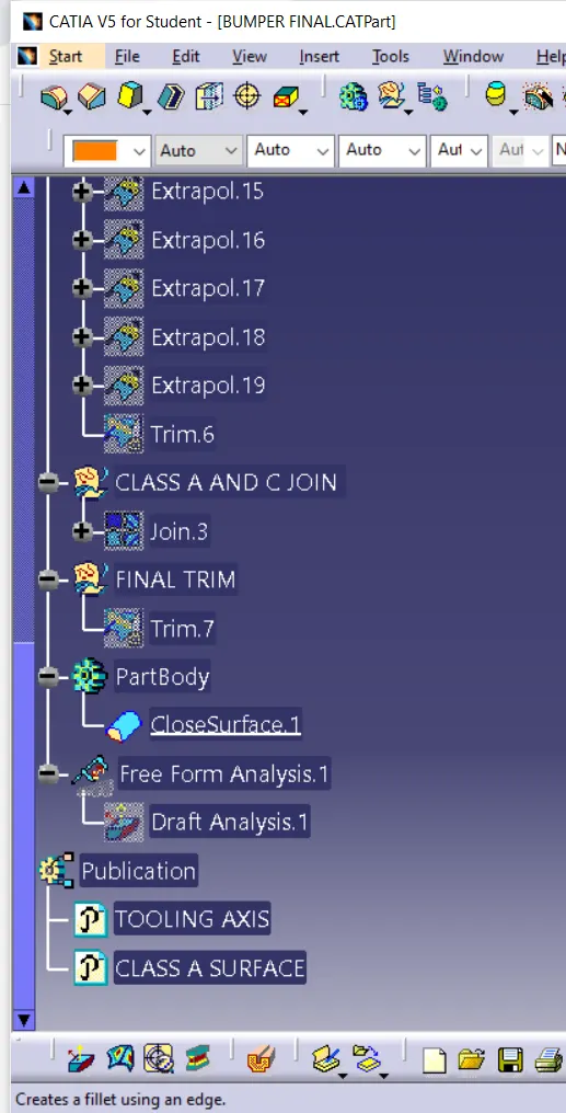
EXPANDED TREE STRUCTURE:-
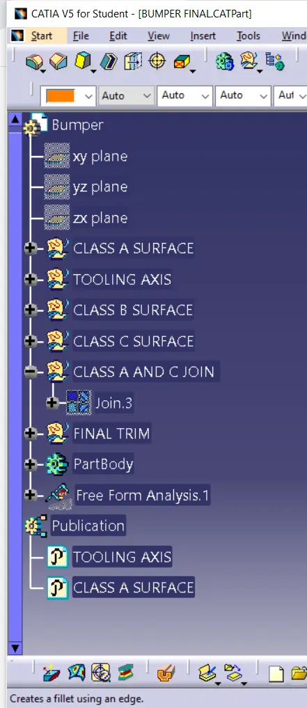
PUBLICATION :-
Publication is use to easy accessible of given command and drawing .
CONCLUSION:-
How to form the tooling axis when there are constraints .
To capture the class B and C properly.
To check the feasibility of the component.