Week 9 - Challenge 3 - Bumper
Ans:
OBJECTIVE:
Create the Bumper Plastic component through the given Class-A surface. To begin with, the tooling axis for the given Class-A Surface should be created meeting the requirements of the draft angle and at the end perform the Draft analysis on the model.
INTRODUCTION:
CLASS-A SURFACE: A surface made by the designer which is given as input to the plastic modeler to work on. It is an aesthetic surface
and the outermost surface.
CLASS-B SURFACE: A surface below a certain thickness from the class-A surface is a class-B surface. This is the surface that contains
engineering aspects of a model.
CLASS-C SURFACE: A surface that joins class-A and class-B surfaces is a class-C surface.
INPUT GIVEN:
-
A-Surface
-
The thickness of the component is 3.00mm
- The draft angle is 3 degrees.
PROCESS:
In this model we have focused on the following things:
Tooling axis
Draft analysis
Class-B surface
Class-C surface
Making a solid model from the surface.
The following tools were used to reach the final step:
Extract
Un-trim
Trim
Extrapolate
Offset
Edge fillet
Boundary
Sweep
Join
Close (part design)
CREATING OF TOOLING AXIS:
The tooling axis is the direction in which a core or cavity of mold opens. This Axis is very important to determine the orientation of the component in mold, core, and cavity design.
The tooling axis is created by the inertia method by using the steps as follow
-
Click “Measure inertia” and select the A-surface
-
Click “Create geometry” in the Measure Inertia window.
-
In the Creation of Geometry window, select Non-associative geometry.
-
Click “Center of Gravity”
-
The Inertia point is created.
-
The component is viewed in all axes namely X, Y, and Z.
-
It is determined that the X-axis will be the direction for the Tooling axis and a line is created Using the CG point and X-direction as the direction of the line.
Now FOR DRAFT ANALYSIS:
First, we analyze the model and then choose a dummy axis in the x and y direction.
As we intersected to proceed we observed that the side walls are not given any draft. Hence we assume the axis normal to the base surface and parallel to the side walls. This indeed will create problems because a minimum draft has to be provided.
As the class-A surface is made by another designer only he is authorized to make changes, so we look over this to complete the coin holder for practice.
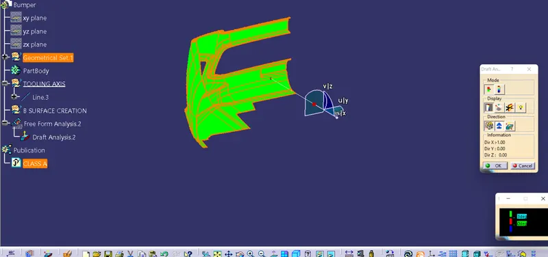
Now we go to insert< analysis< draft analysis and follow the usual procedure to do the analysis.
Align the compass and click on the surface and as expected the model is mostly in red i.e. negative draft concerning the axis.
To correct it as best as we can we moved the compass a bit till we got most of the surfaces in green and lock that position.
After hitting ok, we change the direction of the line from the z-axis to the compass direction. The axis will align itself accordingly.
NOTE: as the side wall does not have a draft, this result was expected and a few areas need correction. But still, we are moving forward to complete the model.
CHECKING THE INPUT - A SURFACE:
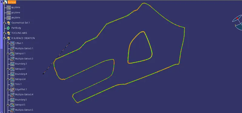
The A-surface or the styling surface is first checked for any gaps and other issues in its surfaces. This Surface acts as the input surface so any correction to be done should be with approval from the styling team or done by them. A- perfect surface is the one when a boundary is created, the lines are only on the edges of a component and its holes or cutouts as shown below.
DRAFT ANALYSIS OF A SURFACE:
Draft analysis of the surface is carried out to check if the surface or part can be manufactured with the required draft angle.
A draft angle is needed for the component to clear the core and cavity surface as it would have shrunk towards the center while cooling.
The draft angle in this design is 3 degrees. As A surface is a single surface there won't be much color difference.
CREATING OF B-SURFACE :
The A-surface is offset by 3.00mm as it is the thickness required.
The Areas where the B-surface has issues are corrected by closing them using commands like Multi-section, Sweep, Offset, and extract.
Finally, all the created surfaces are trimmed or joined together with offset surfaces done earlier. This created a single surface that will act as the final B-surface.
B surface created is checked for any gaps or errors by creating a complete boundary.
CREATING OF C-SURFACE :
The A and B surfaces are connected by another single surface which is called the C surface.
It is created by using a sweep with A surface acting as the reference surface and a curve created from the boundary of the same surface.
Sweep with draft direction is also used to create A-surfaces.
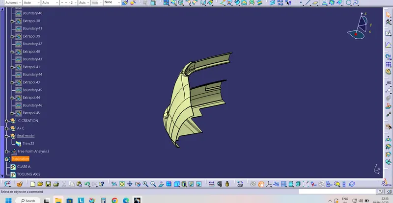
Following is the picture of the Class A + Class C surface trimmed together
CREATING OF CLOSED BODY :
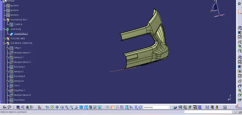
All the surfaces (A, B, C) are joined together to form a closed body.
The boundary is selected and the body is picked. Since an error popped up it can be understood that all surfaces are joined with each other to form a proper closed surface body.
Finally in part design workbench, using close volume is changed to a solid body.
MODEL TREE:
The model tree created shows that all the geometrical sets are named for clarity.
The publications of the Tooling axis, and surfaces of A, B, and C surfaces are done.
Also, the closed surface body and Volume are published.
DRAFT ANALYSIS OF PART BODY:
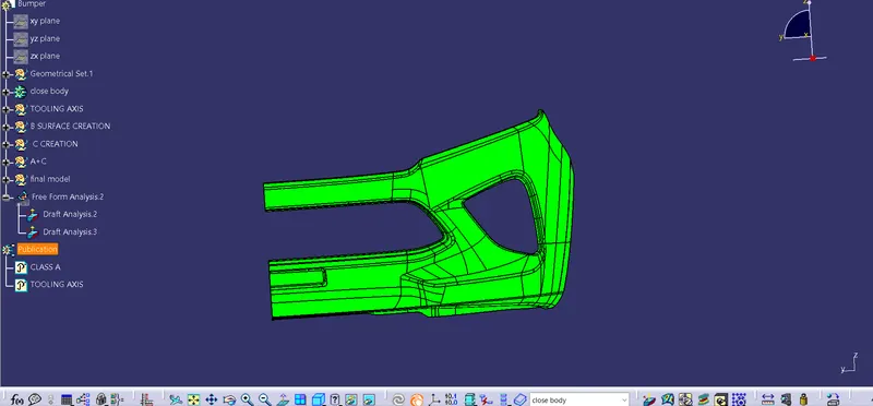
The final solid part body has to be analyzed using Draft analysis. This is done to check if all body areas are satisfying the draft angle, which is 3 degrees.
A draft angle is a taper applied to the vertical walls of the injection-molded component to assist with releasing the part from the mold.
Draft angles are a required feature of injection-molded custom parts. A functional part for injection molding has to have draft angles that face both the cavity and core sides. This will reduce the risk of damage to the parts and ensure that they can be ejected from the machine.
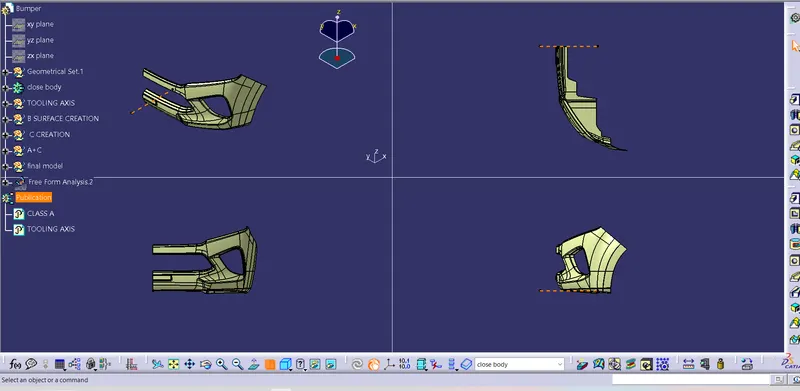
The Bumper body is checked using Analysis and images for it is shown below.
Views from the different orientations of the Bumper Part Body:
Conclusion:
The Draft analysis of the component showed that the component is feasible to be molded without any issues,Thus it satisfies all design and manufacturing criteria needed for a proper part.