Week 9 - Challenge 3 - Bumper
BUMPER
OBJECT:- Create a tooling axis in a proper way for finding a better draft analysis from the
given class A surface. Create a draft analysis of the class A surface and create a class B
and class C surface from the class A surface. And finally, create a draft analysis of the
finished body.
Consider the thickness of the component 3 mm.
Introduction:- This project is done on CATIA software. This software is diffrent from others.
It is easy to design for surface modeling. Its have more accuracy than other.
Class A Surface:-
In automotive design applications Class A Surface are create on all visible exterior
surfaces (ex; body panels, bumper, grill, light, etc.) and all visible surfaces of see-touch &
feel parts in the interior (ex; Dashboard, seats, door pads etc). This can also included beauty
covers in the engine compartment, mud flaps, trunk panels, and carpeting. This surface
has a 0 mm thickness.
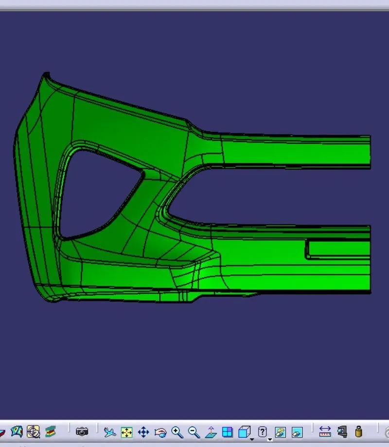
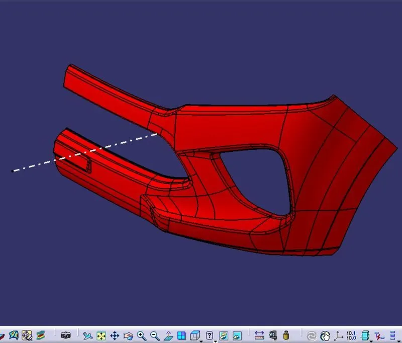
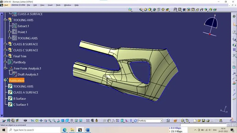
Given Class A Surface
Tooling Axis:-
Tooling axis or tooling direction is main consideration for plastic part and mold parts
because it defines movement of mild part and possibility of plastic part to come-out from
mols part (Core and Cavity). In Molding machine arrangement is given to open the mold
along a direction which is known as Tooling Direction. The mold is built from two seperate
halves (Core and Cavity ) and tooling direction basically define the direction of mold pulls
apart. Tooling direction is known as primary direction.
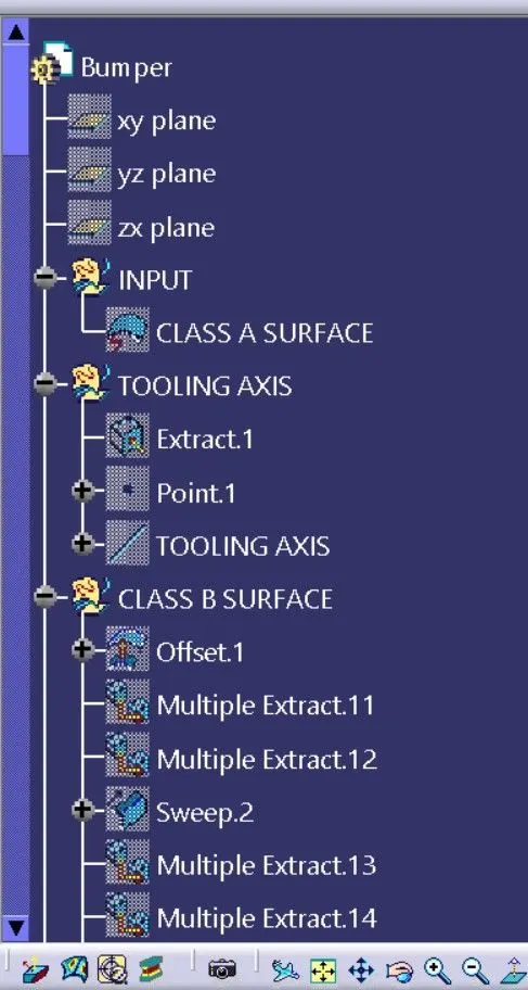
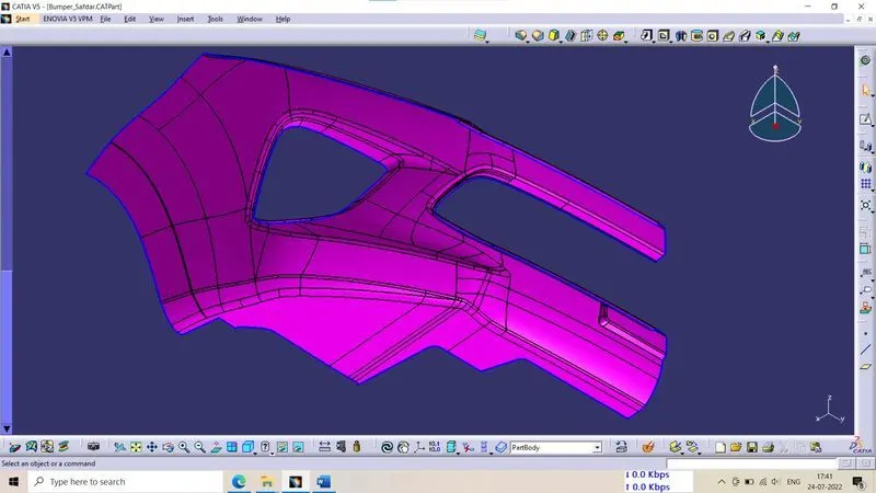
. Here i have create a tooling axis. First of all i extract a base surface and create a mid point
on it. And then i create a line through this point with perpendicular to base surface. And
then i performed draft analysis and i saw every things is ok. Then finally it is my tooling axis.
Draft Analysis:-
The Draft Analysis allows the user to easily analyze a part for proper draft angle. A
Draft Angle describes the amount of taper for molded or cast parts perpenicular to the
parting line. Draft Analysis is applicable for 3D part models. To create a draft analysis for
any 3D part file, the user needs to select part/surface select the pull direction. You can
change the pull direction.
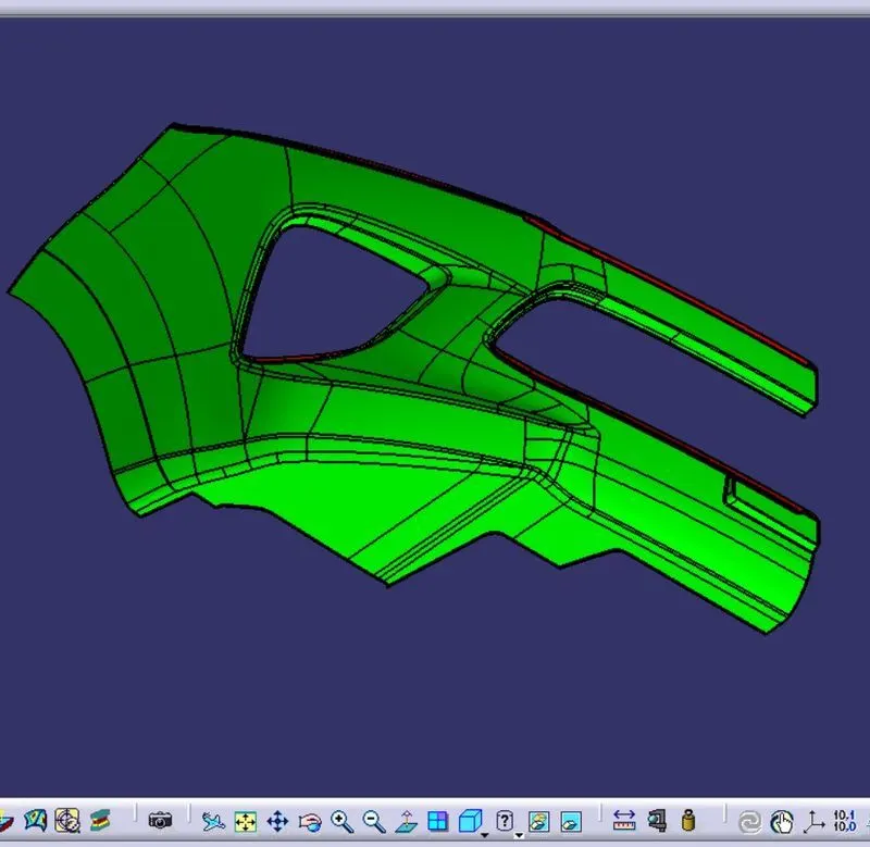
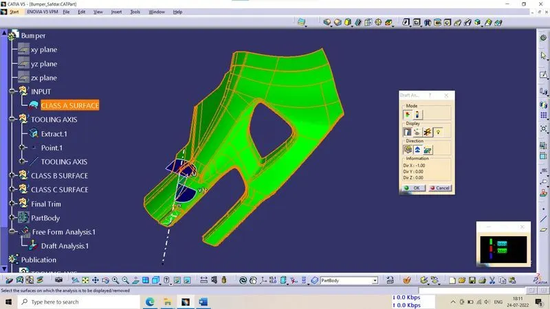
Draft Analysis of Class A Surface In CATIA:- It provides color based identification. With the
help of this we can easily find that which surface is in clear and which is in stuck by color
changing. Here i give the draft angle 3 degree. The result in color based that the surface
which green (means draft angle > degree) is right. And where the colour is blue mean
draft angle is 3 degree to 0 digree if this surface area is low then you can go. If you find red
color zone then it means draft angle is less than 0 degree. Then you will have to create
tooling axis by another way if possible, otherwise you can say your design engineer to
correct for designing.
Class B Surface:- The surface which is back side of Class A surface is callled Class B surface.
Mostly it not visible. It is create with the help of Class A surface with some distance (thickness)
like 2mm, 3mm etc.
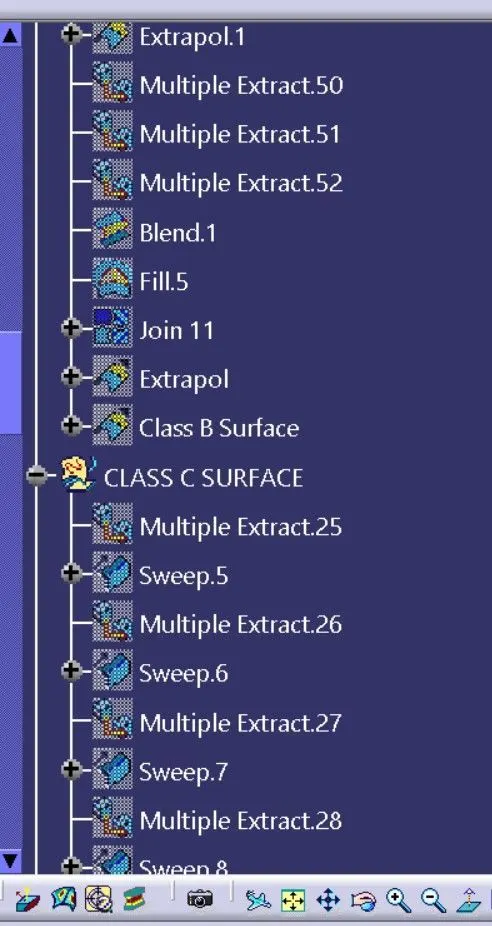
. Here i create Class B surface on 3mm from Class A Surface.
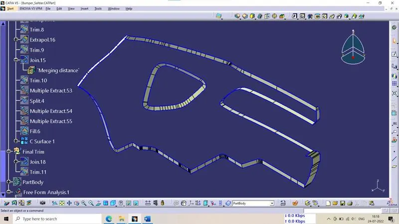
Class C Surface;- The Class C surface is the back side of a part of a surface that is perpendicular
covered by another part.
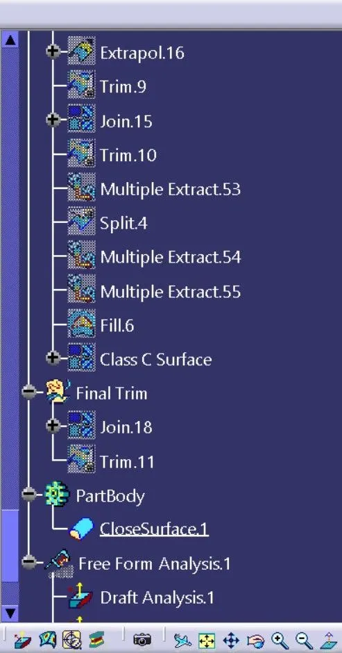
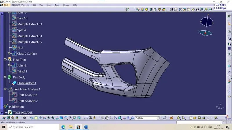
. With the help of join and trim feature i have created a closed surface body.

Draft Analysis of Part Body:-
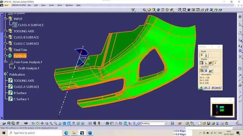
I have allready above on it. You can see there.
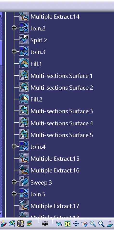
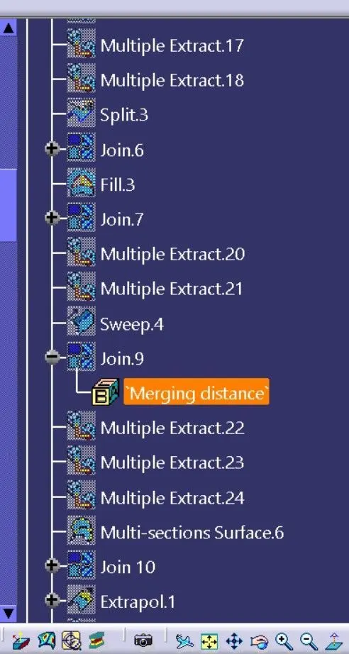
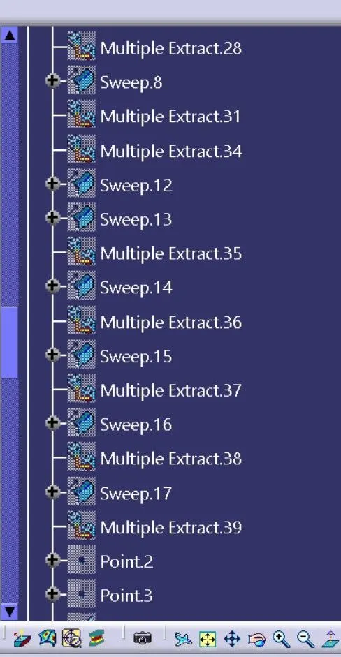
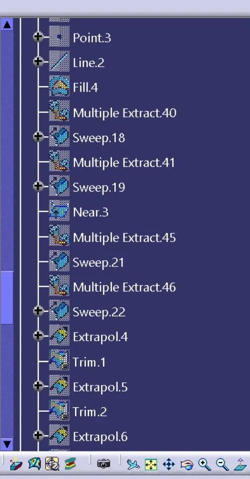
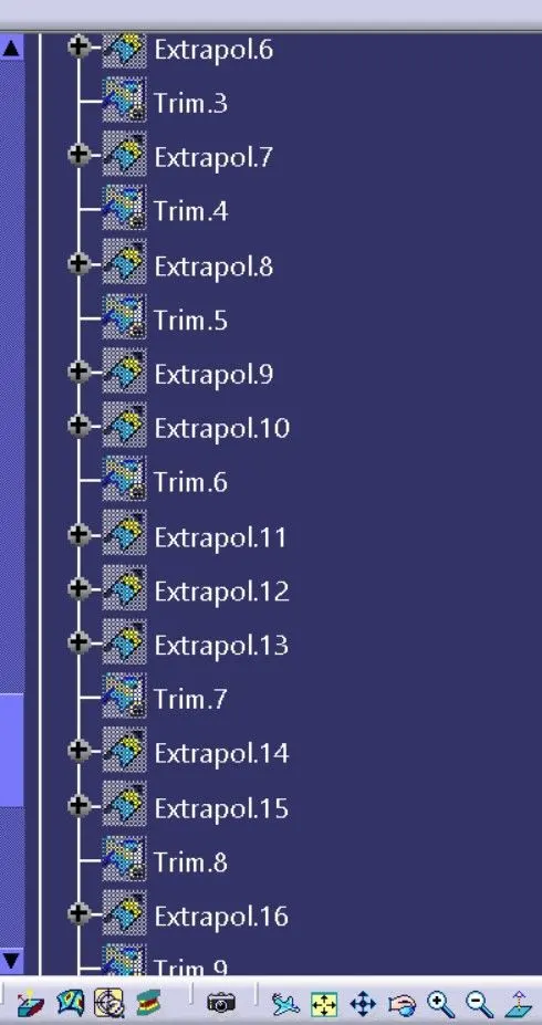
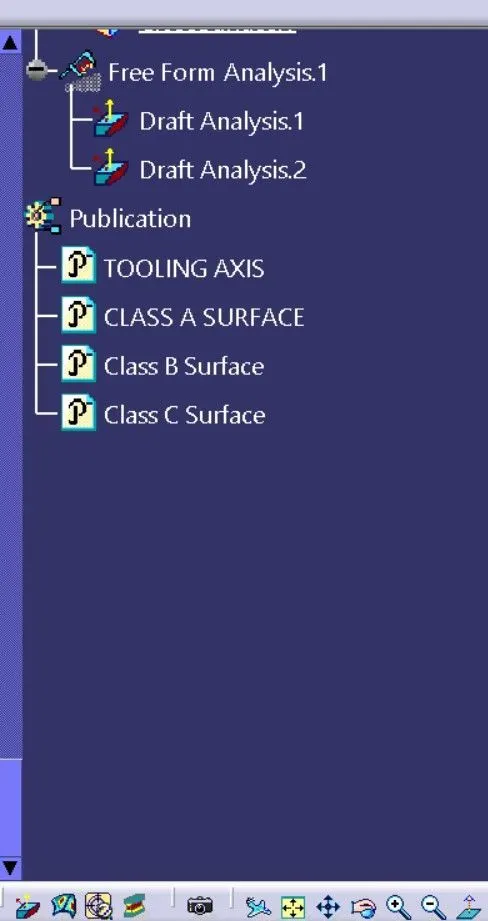
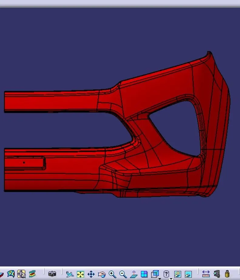
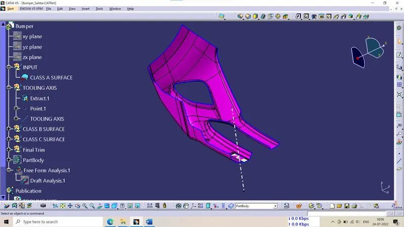
Feature Tree and Some View of this Part:-