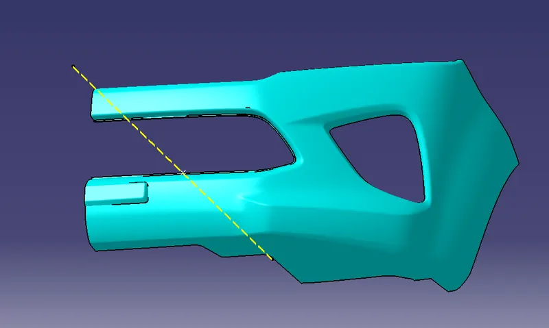
Week 9 - Challenge 3 - Bumper
PROJECT NAME -: BUMPER CHALLENGE
AIM-:
- CREATE THE TOOLING AXIS.
- CREATE THE CLASS B AND CLASS C SURFACE.
- DRAFT ANNALYSIS OF CLASS A AND FINAL SURFACE.
- CREATE CLOSE SURFACE COMMAND.
A. TREE STRUCTURE
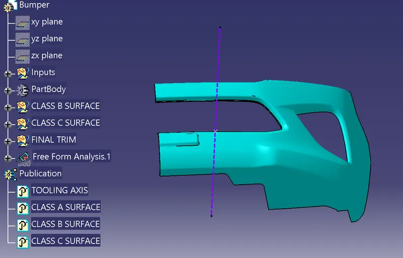
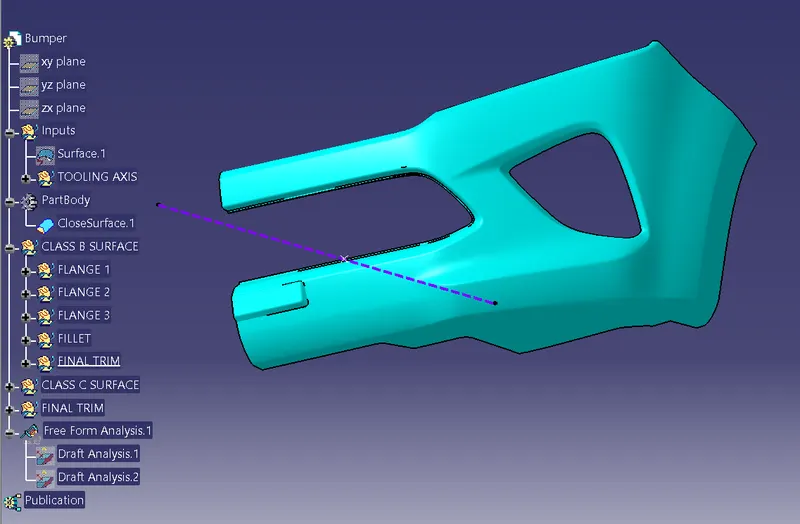
B. DETAIL TREE STRUCTURE
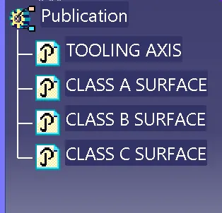
C. PUBLICATION
D. PROCEDURE FOR CREATING A TOOLING AXIS-:
Surface is irregular. I choose Reference on surface for creating tooling axis instead of bisecting method. So, fpor that first choose the axis from which maximum visulaization of component is possible. Then start using the procedure for creating tooling axis.
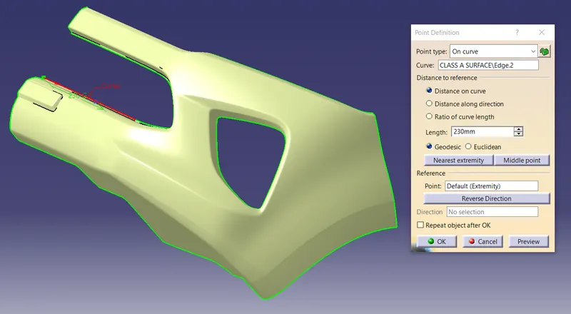
1. CREATE POINT ON CURVE
- Choose "Point" option in "Wireframe" toolbar.
- Choose "On curve" option in "Point type".
- Select the curve.
- Choose "Distance on curve" option in "Didtance to reference".
- give the distance of point.
- Point is created automatically.
2. CREATE LINE ON POINT
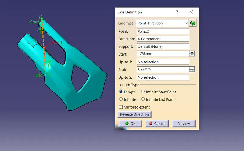
- Choose "line" option from "Wireframe" toolbar.
- Choose "Point-Direction" option in "Line type".
- Select the point.
- Choose "X Component"(Maximum visualization direction) in " Direction".
- Enter value for "Start" and "End" limit or set length by drag option.
- Choose "Length" in "Length Type" then click "ok".
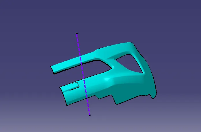
- Do the draft annalysis by taking this line as axis.
- The surface is shown in green colour, it means this tooling axis is correct.
- Right click in "Line" from "Sub Tree", choose Properties, then "Feature Properties" and write name as Tooling Axis.
In this way Tooling Axis is created without using bisecting method.
E. PROCEDURE OF DRAFT ANALYSIS OF CLASS A SURFACE
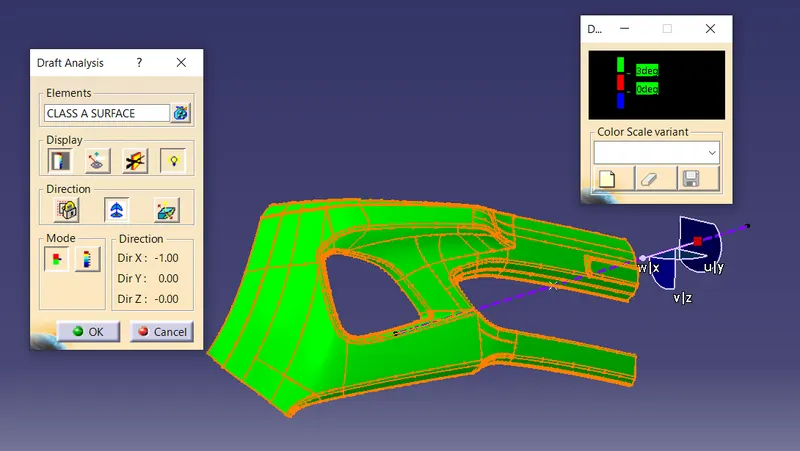
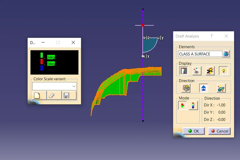
- Go to "Insert" toolbar, then choose "Analysis", then choose "Feature Draft Analysis".
- Choose "CLASS A SURFACE" in "Element" option.
- Choose "Shows or hide the color scale" in "Display" option.
- Deselct the "Analyses under the running point" if you don't want to check the running point angle.
- Select "Uses the compass to define the new current draft direction" option.
- Drag the compass and placed it in Tooling axis line vertically.
- Choose "Inverses the draft direction" option as per required.
- Choose "Switch on the quick analysis mode".
- Enter the draft angle value by double clicking on it.
RESULT-:
- If "CLASS A SURFACE" show green colour in top side, it means it created with proper draft angle in limit and no further correction required for this surface.
- If "CLASS A SURFACE" show Red or Blue colour in top side, it meand the draft angle is not given in limit and then correction or working is required on this surface.
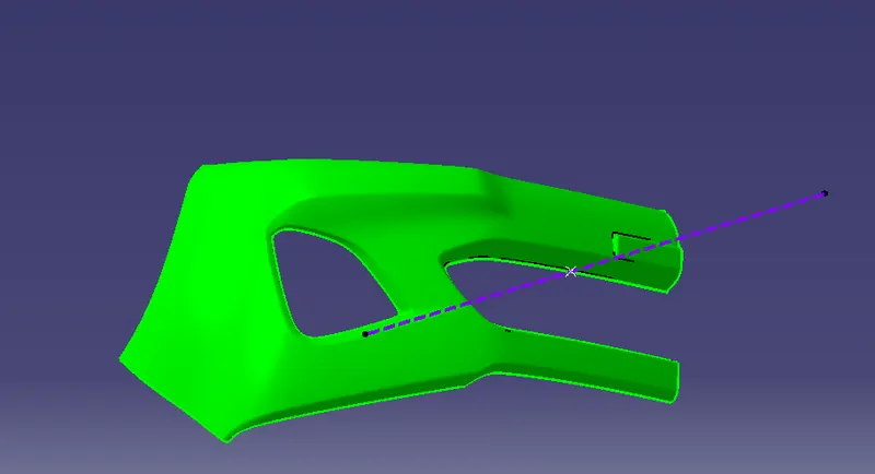
1. ISOMETRIC VIEW
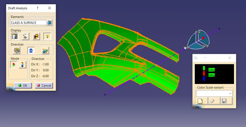
2. FRONT VIEW
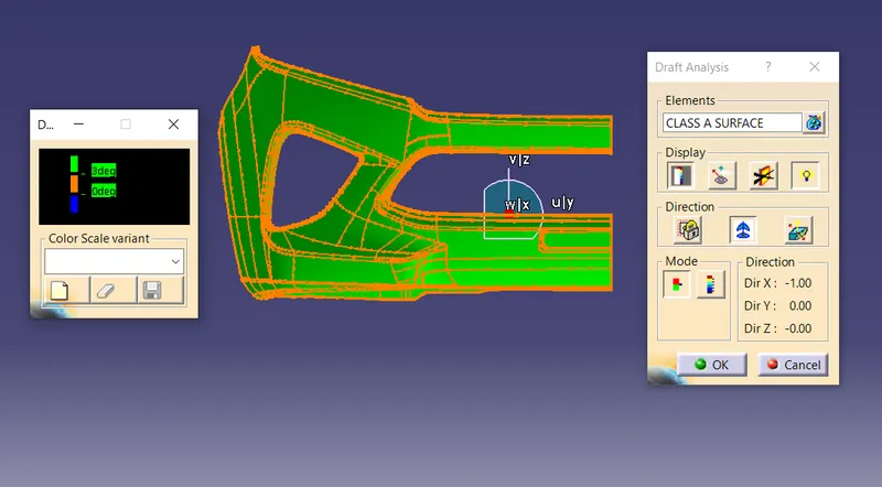
3. SIDE VIEW
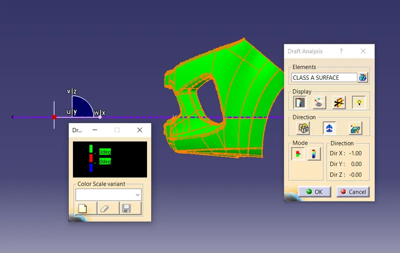
4. TOP VIEW
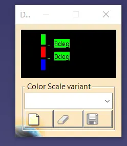
5. COLOUR SCALE
F. PROCEDURE OF DRAFT ANALYSIS OF CLOSE SURFACE:-
- Go to "Insert" toolbar, then choose "Analysis", then choose "Feature Draft Analysis".
- Choose "CLOSE SURFACE" in "Element" option.
- Choose "Shows or hide the color scale" in "Display" option.
- Deselct the "Analyses under the running point" if you don't want to check the running point angle.
- Select "Uses the compass to define the new current draft direction" option.
- Drag the compass and placed it in Tooling axis line vertically.
- Choose "Inverses the draft direction" option as per required.
- Choose "Switch on the quick analysis mode".
- Enter the draft angle value by double clicking on it.
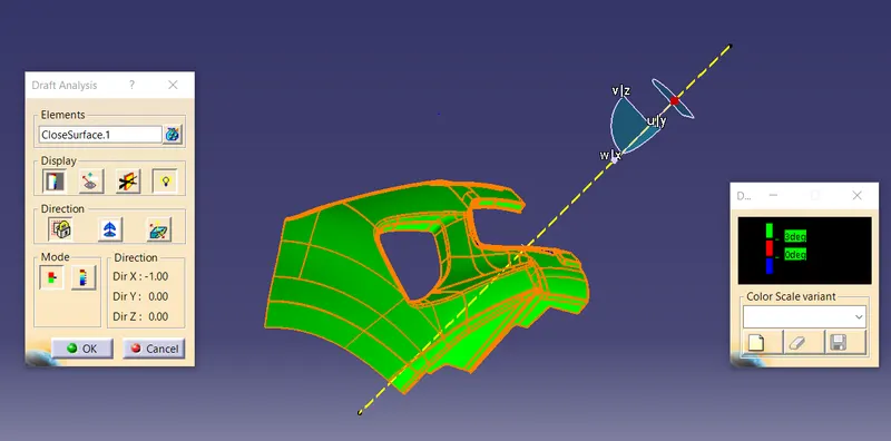
RESULT-:
If "CLASS A SURFACE" show green colour in top side, it means it created with proper draft angle in limit and no further correction required for this surface.
- If "CLASS A SURFACE" show Red or Blue colour in top side, it meand the draft angle is not given in limit and then correction or working is required on this surface.
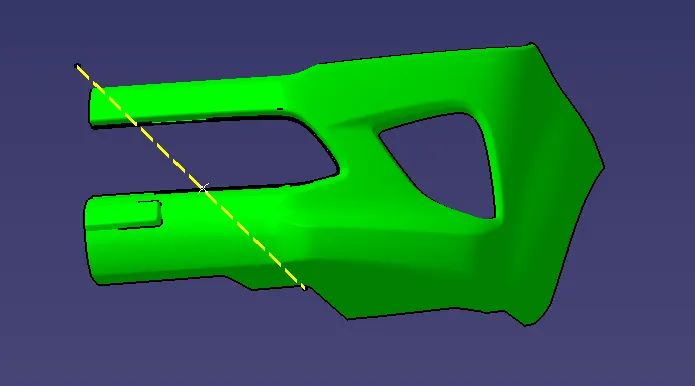
1. ISOMETRIC VIEW
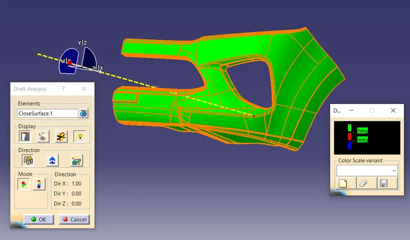
2. FRONT VIEW
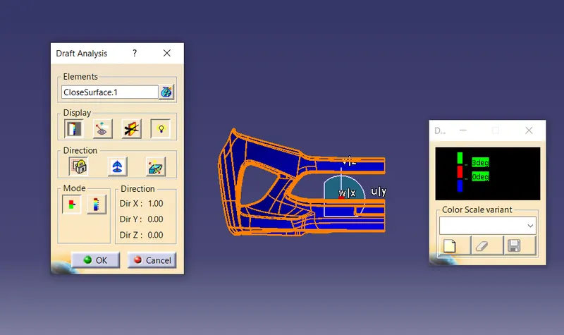
3. BACK VIEW
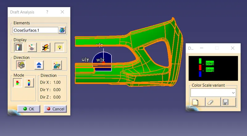
4. SIDE VIEW
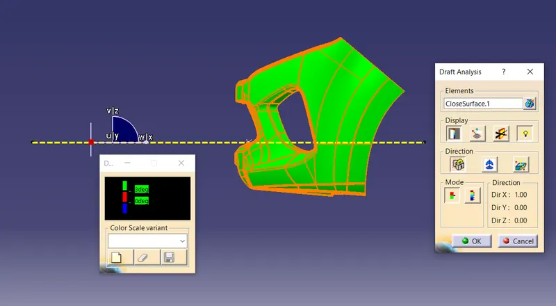
5. TOP VIEW
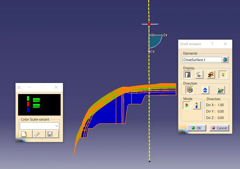
6. BOTTOM VIEW
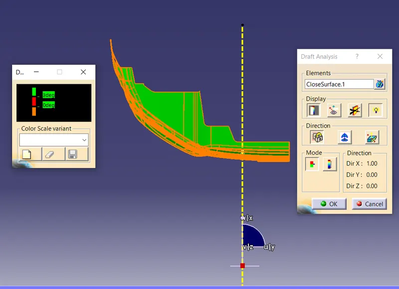
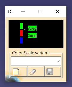
7. COLOUR SCALE
G. SOLID BODY