Week 9 - Challenge 3 - Bumper
FRONTAL BUMPER SYSTEM-
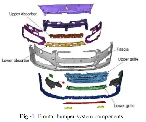
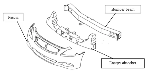
Frontal bumper system consists of three main components as follows-
- Fascia
- Absorber
- Bumper beam
The fascia is usually used for aesthetics and for decreasing the aerodynamic drag force. It cannot tolerate to impact energy,
thus it is considered a non-structural component.
The absorber is designed to dampen a portion of the kinetic energy from a collision.
The bumper beam is a key structure that helps to absorb the kinetic energy from a high-impact collision and to provide bending resistance in a low-impact collision.Bumper beam will absorb the impact collision energy in a controlled manner before the energy gets transferred to the passenger compartment.
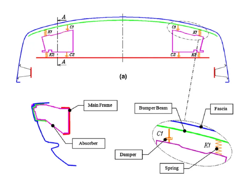
Product design specifications(PDS)
The PDSs are a list of the product specifications corresponding to customer’s requirements or expectations compiled in a detailed technical document.In the case of the bumper beam, the PDSs address safety, performance, weight, size,cost, environmental issues, and appearance. In other respects, the PDS parameters in general can be classified into three
main subdivisions: material, manufacturing, and design.
Examples on safety regulations for the passenger’s cars bumper systems include those issued by
The United Nations Economic Commission for Europe (ECE) Regulation No. 42
The International Highway Traffic Safety Administration (NHTSA)
The Canadian Motor Vehicle Safety Regulation (CMVSR) Code 49 Part 58
Danner(RCAR),EURONCAP,IIHS high speed crash
All these safety regulations needs to be compliant to a set of three tests:
1.Low-speed test impact test: tested for functionality and serviceability of all components
2.High speed impact test:Lateral bucking of rails, no Bumper damage & no intrusion for total energy absorption.
3.Pedestrian test-lower stiffness in dissipation of impact energy,elastic energy absorption before any plastic yielding of the bumper beam takes place.
Size:Dimensions of the bumper beam depend on the size and weight of the vehicle and on the target value of energy absorption.
Maintenance: Design for assembly and DFM should be considered during product design.
Performance: The defined goal of the product should be attainable.
Installation: Design for manufacturing and assembly (DFMA) helps in minimizing the bumper components in the product or
assembly to allow for easy assembling with optimized fixing point.
REPORT ON ANALYSIS OF CLASS A SURFACE-BUMPER
1.Visual Inspection -
- The first step of the draft analysis is to determine whether the given class A surface contains any side core functionality that needs to be achieved in the component during manufacturing by injection molding.Also,check for any open surface patch/incomplete model geometry.
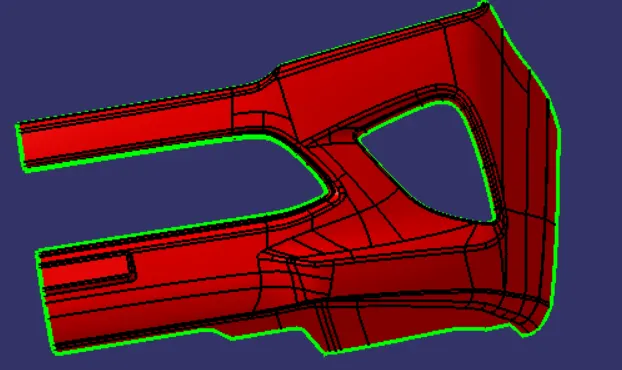
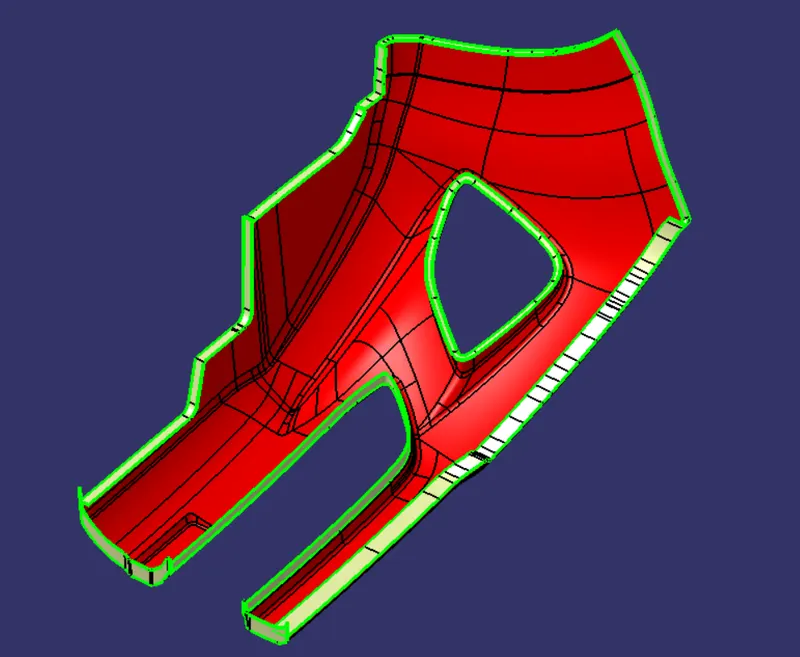
- This can be done by visually checking/inspecting the class A geometry completely feature by feature.Use Surface boundaries in Tools - Options - Display - Visulaization.This helps to check closed surface boundary.
- Use Join/boundary command to check if all surface edges are closed.
- Any basic geometrical features such as chamfer,fillets,holes are assumed to be cleared through the direction of tooling axis i.e,..perpendicular to that of the tooling axis.
2.Understanding injection molding process -
- Any geometrical surface that are not aligned to perpendicular direction of the tooling axis needs a separate side core in the mold to create the injection molded component.
- Plastic injection molding process requires core and cavity to form a plastic component.Under injection of high pressure the plastic components is formed.The direction of movement of the core and cavity where it opens and closed is said to be the tooling axis.
- Apply nominal draft of upto 3 deg on both side i.e.. 1 1/2 deg each side to the surface,according to the design rules for plastic injection moulding component this allows for easier ejection and no defects after cooling.
3.Creation of Tooling axis -
- After the proccess of visual inspection,we know that for given Class A surface of frontal bumper does not require any side core for plastic component to be produced.The next step involves in deciding the tooling axis selection,this can be x,y or z direction.For frontal bumper the tooling axis can taken from x-axis as the geometry of frontal bumper is perpendicular to that of tooling axis.
- The creation of tooling axis is determined by tooling direction which can done by checking all the axes individually for the feasability of manufacturing.This procedure can be implemented with point on surface method(flat surfaces) or bisecting method(complex geometry)
XY-PLANE - Z AXIS
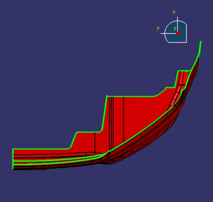
YZ-PLANE - X AXIS
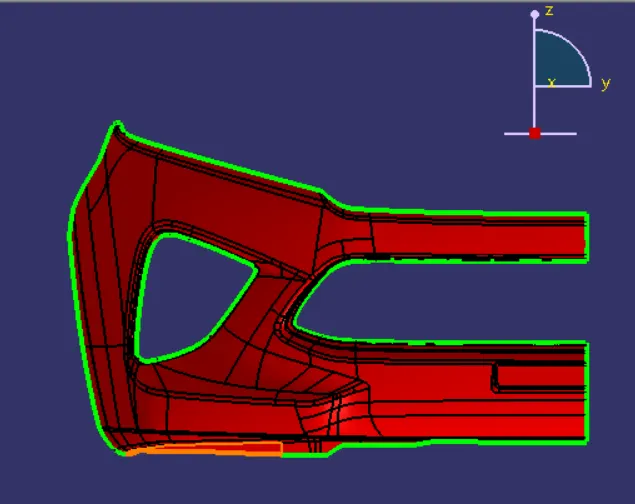
ZX-PLANE - Y AXIS
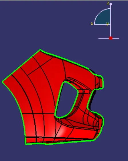
- In the given Frontal bumper class A surface,there is no side core requirement to produce the component with respect to tooling axis at tooling direction x-axis
- Create an axis system on the Frontal bumper by using point- on surface to create a reference tooling axis.In this case,any flat surface normal to the x-axis is an ideal choice to create a reference axis.
CREATION OF CLASS B SURFACE-
- In this approach,the class B surface needs to created with the help of
 offset command,The offset distance should be eq(=)to that of the thickness of the component.Let's say its 3 mm in the inward direction of class A surface(below).
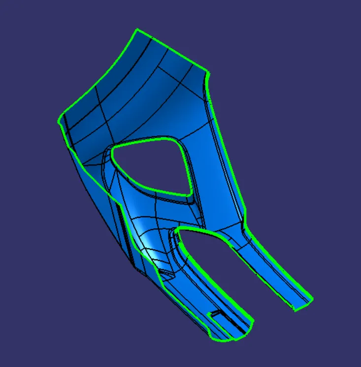
- The direct offset method will help in creating complex geometrical surfaces,however we will face some geometrical issues while offsetting, the offset surface will result in incomplete surfaces because of complex edges and fillet regions
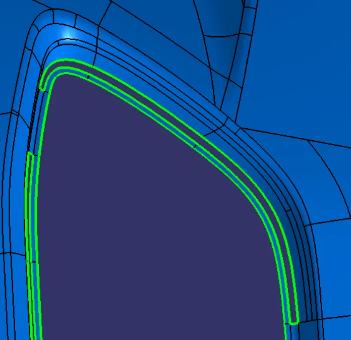
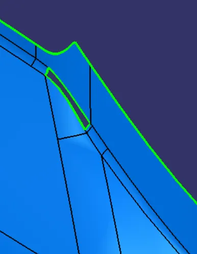
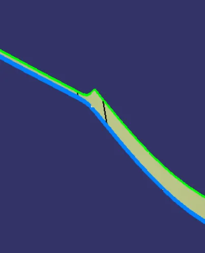
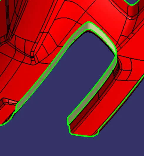
- These open patches needs to fixed with help of Multiple extract
 to get two geometry of surfaces as reference which will be needed to extrapolated and trimmed,img (1)
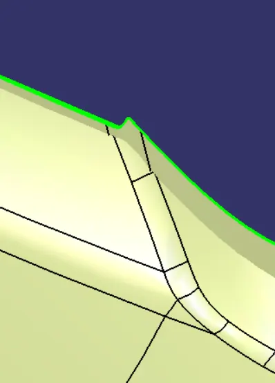
 - Boundary
 is used to get the edge of the surfaces to be extra polated seperately,img (2)
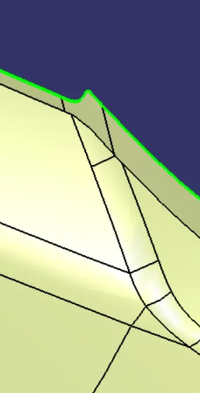
 - Extrapolate
 is used to extend the length of the surface/edge.This needs to be xtrapolated untill both the surfaces meet and then extend even more in order to be trimmed,img(3)
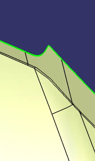
 - Trim
 command is utilized to trim both the surfaces to form sharp edge,img (4).
 - Edge fillet is used to round the edge by measuring the fillet on class A and reducing the value with offset distance, this process is repeated untill all the opened patches are fixed in offset surface to obtain a class B surface,img (5).
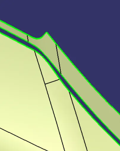
img (1) img (2) img (3) img (4) img (5)
CREATION OF CLASS C SURFACE-
- In order to create a class C surface which will join the class A & B,the tooling axis is required for the class A surface which has been created already.
- Now, using boundary ,with limitations 1 &2 select all edges seperately on the class A surface,like so.
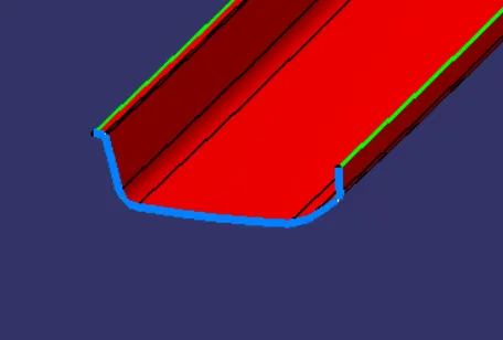
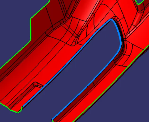
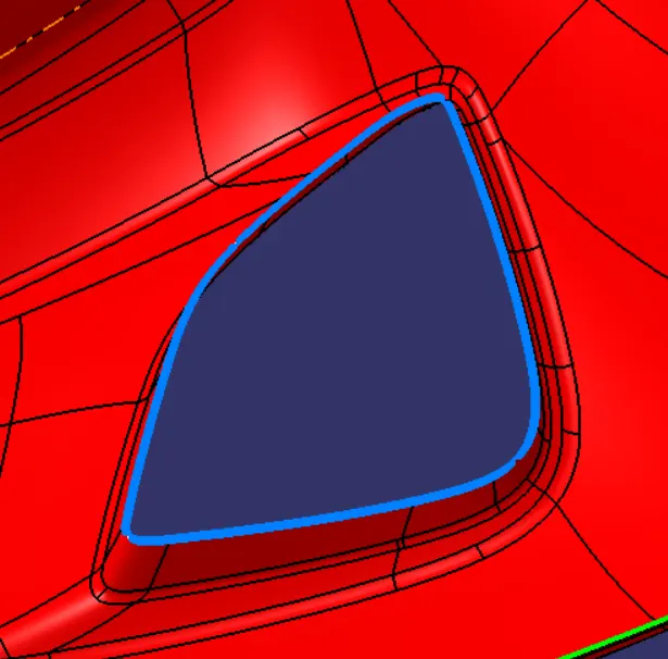
- Use swept surface
 ,in profile type select line-draft direction- select the tooling axis created, enter angle - 3 deg to sweep the surface parallel or perpendicular to tooling axis depending on which axis the edges are normal to.
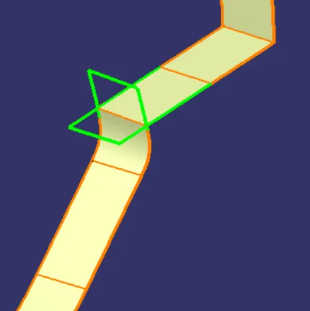
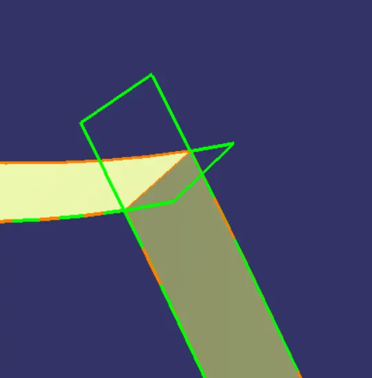
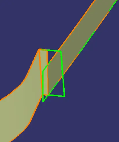
- Swept surface of all edges needs to be extrapolated and trimmed to form a single class C surface.
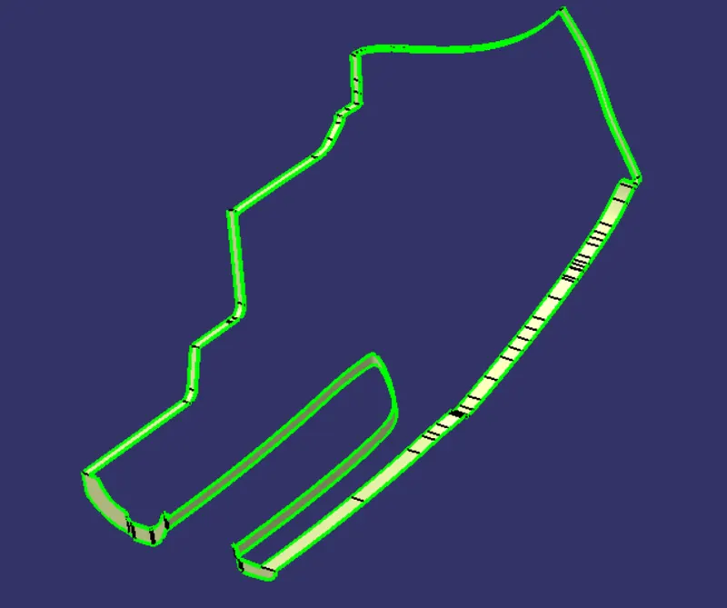
CREATION OF CLOSED SURFACE -
- Join command
 is used to combine two surfaces.In partbody,Insert - surface based features - close surface.Join the class A and class B to trim with class C surface.
 - This will create a solid closed body.
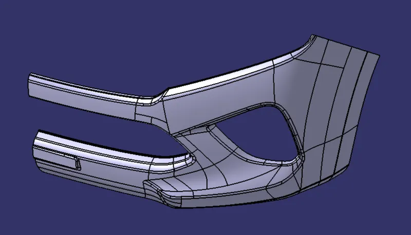
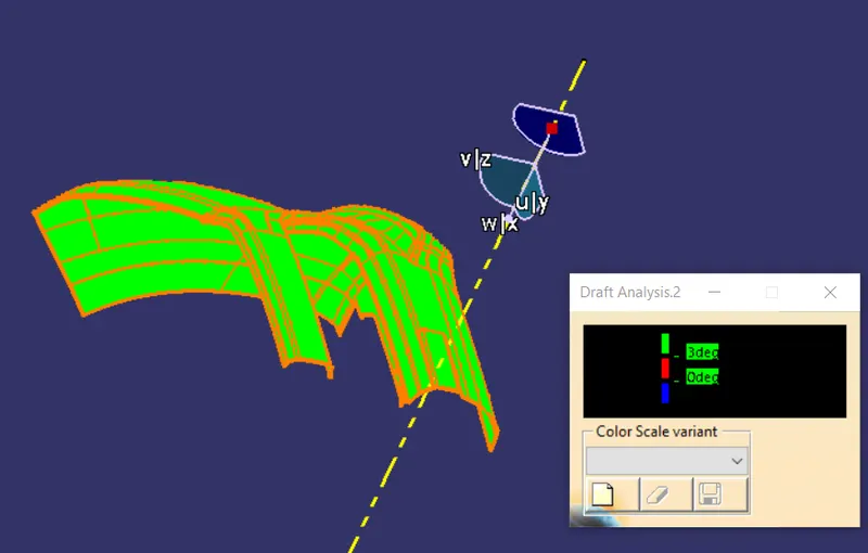
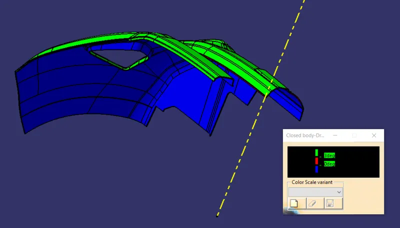
- Perform draft analysis from Insert- Analysis - Feature draft analysis
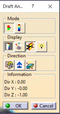
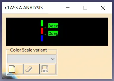
- Enter 3 deg of color scale variant to control the nominal draft angle under which the surface needs to be formed.This color scale can be changed by double-click (or) to color scale mode from quick analysis to full analysis mode
- Then,use angle running point
 for identifying angle of the surface.
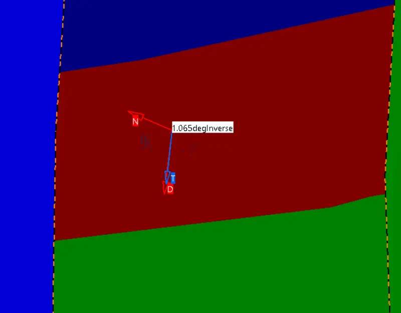
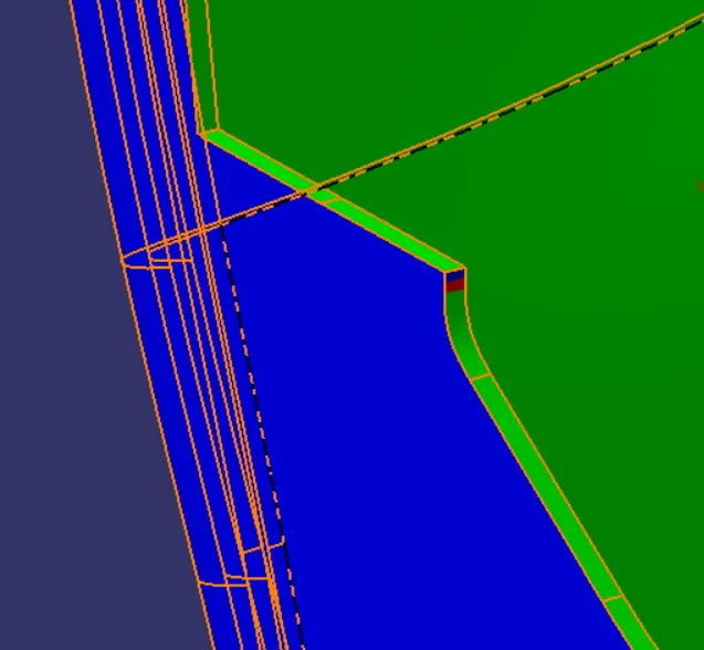
- By using the running point tool we are able to identify that there is a 1.065 deg of draft angle in the given class A surface after a draft analysis.This needs to be highlighted and resolved in terms of manufacturing feasibility if or not the part can be manufactured according to the nominal draft angle or with some acceptable deviation.
RESULTS -
Close body surface
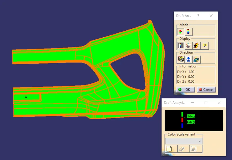
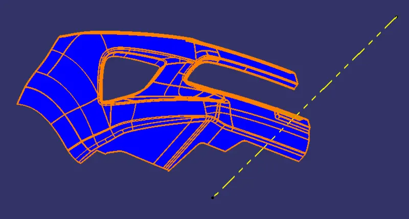
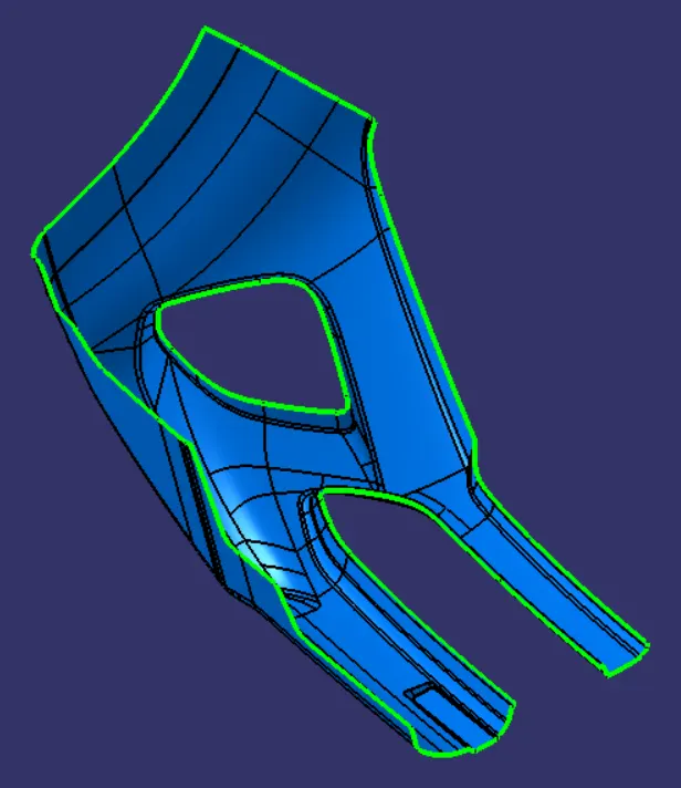
CLASS A surface-