Week 9 - Challenge 1 - Base Bracket Design
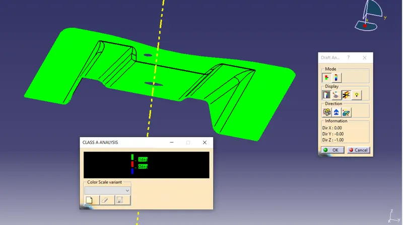
DRAFT ANALYSIS ON CLASS A SURFACE -
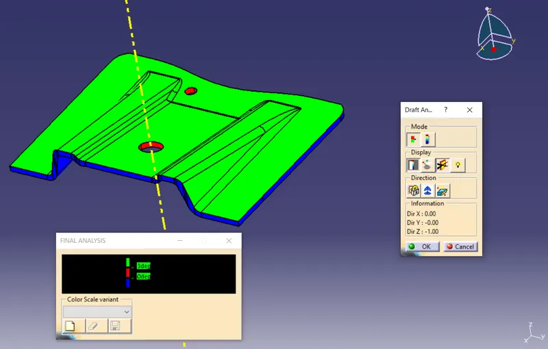
DRAFT ANALYSIS ON FINAL CLOSED SURFACE -
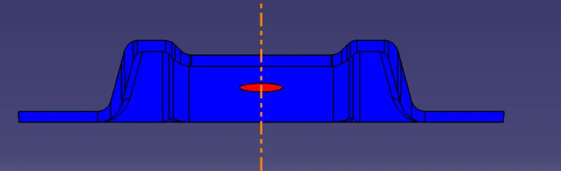
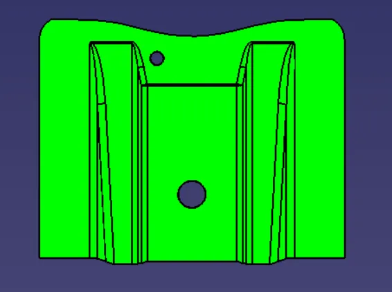
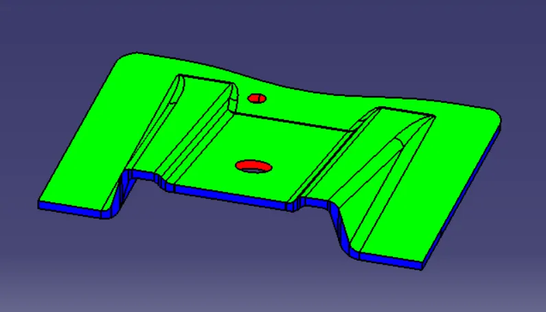
REPORT ON DRAFT ANALYSIS OF CREATION OF CLOSED CLASS A SURFACE -
1.Visual Inspection -
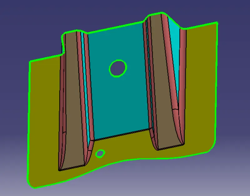
- The first step of the draft analysis is to determine whether the given class A surface contains any side core functionality that needs to be achieved in the component.
- This can be done by visually checking/insepecting the class A geometry completley step by step.
- Any basic geometrical features such as chamfer,fillets,holes are assumed to be cleared through the direction of tooling axis that are perpendicular to that of the tooling axis.
- Use Join/boundary command to check if all surface edges are closed.Use surface boundaries in Tools-options also to ensure proper enclosure of surface.
2.Understanding injection molding process -
- Any geometrical surface that are not aligned to perpendicular direction of the tooling axis needs a separate side core in the mold to create the injection molded component.
- Plastic injection molding process requires core and cavity to form a plastic component.Under injection of high pressure the plastic components is formed.The direction of movement of the core and cavity where it opens and closed is said to be the tooling axis.
- Apply nominal draft of upto 3 deg on both side i.e.. 1 1/2 deg each side to the surface,according to the design rules for plastic injection moulding component this allows for easier ejection and no defects after cooling.
3. Creation of Tooling axis -
- After the proccess of visual inspection,we know that for given Class A surface of base bracket does not require any side core for plastic component to be produced.The next step involves in deciding the tooling axis selection,this can be x,y or z direction
- The features that can be cleared easily which are normal to tooling of your consideration ,let's say z axis.
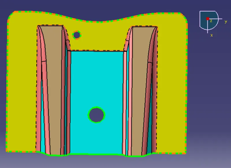
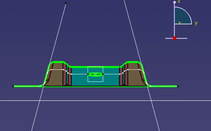
- Check other axes x ,y also where there can be some possibililties of tooling -
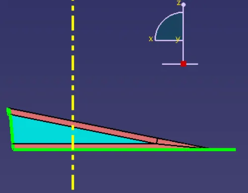
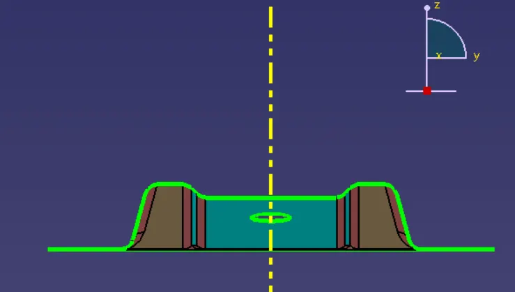
- Here, the two holes and the given surfaces can be formed,only the angle of the surface needs to be considered for draft analysis.
- After identifying the surfaces,perform draft analysis on creating a bisecting line between the two surface lines as reference.Bisecting line is created when two line come into contact and then a line in formed from the contact point to infinite.
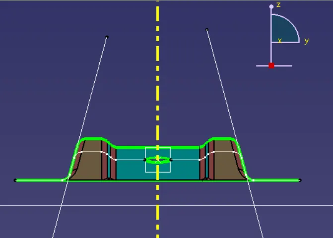
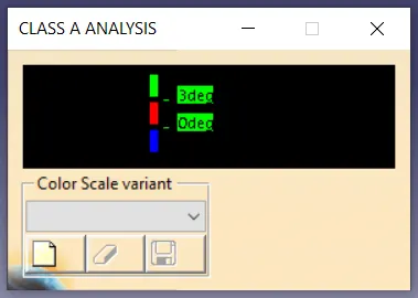
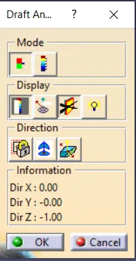
- Enter 3 deg of color scale variant to control the nominal draft angle under which the surface needs to be formed.This color scale can be changed by double-click (or) to color scale mode from quick analysis to full analysis mode
- Pick the Compass
 and place it on the created tooling axis by clicking on the red dot and click and drag.
 - Use
 Lock command to hold in place the compass.
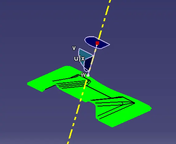
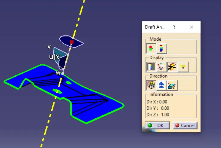
- Then change direction of the draft
 only of required .This changes the core and cavity side with respect to tooling axis
- Then, use angle running point for identifying angle of the surface.
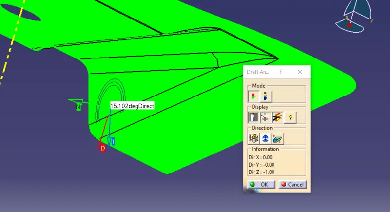
- Click ok to perform draft analysis to the given Class A surface.The result of the draft anlysis will be available under Free form analysis - Draft analysis tree structure.