Week 9 - Challenge 3 - Bumper
REPORT
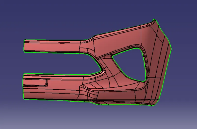
Once we get the CAD file check the quality visually or by using boundary tool
TOOLING AXIS
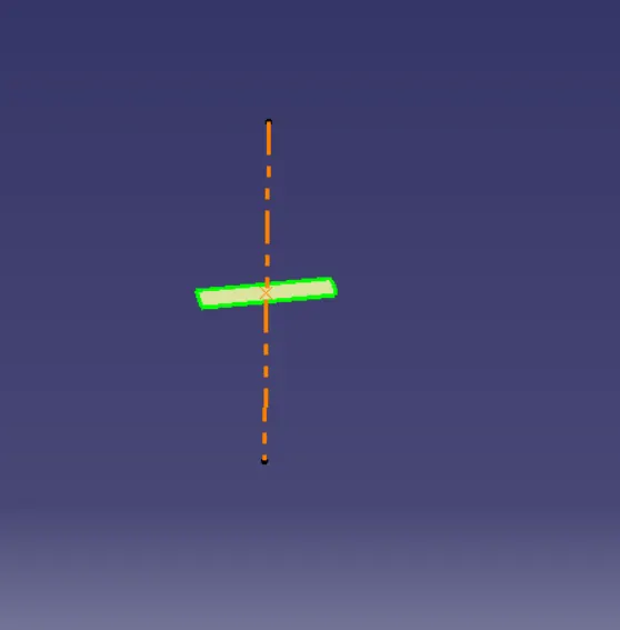
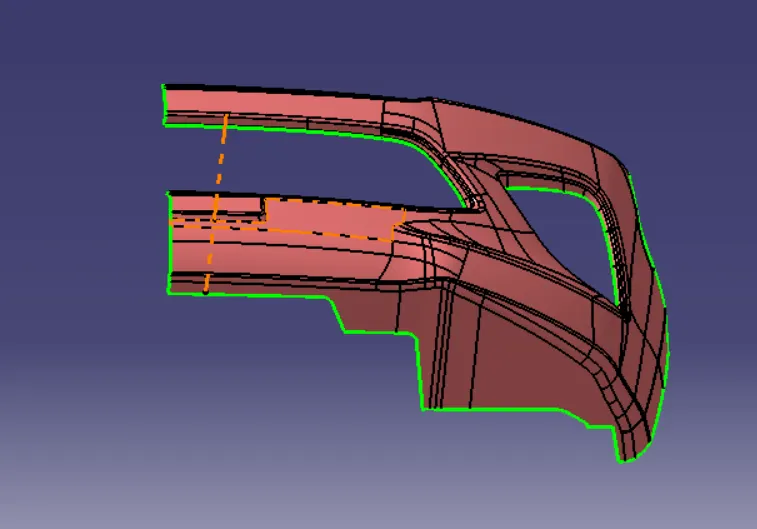
- Lets create a tooling axis using point and direction method
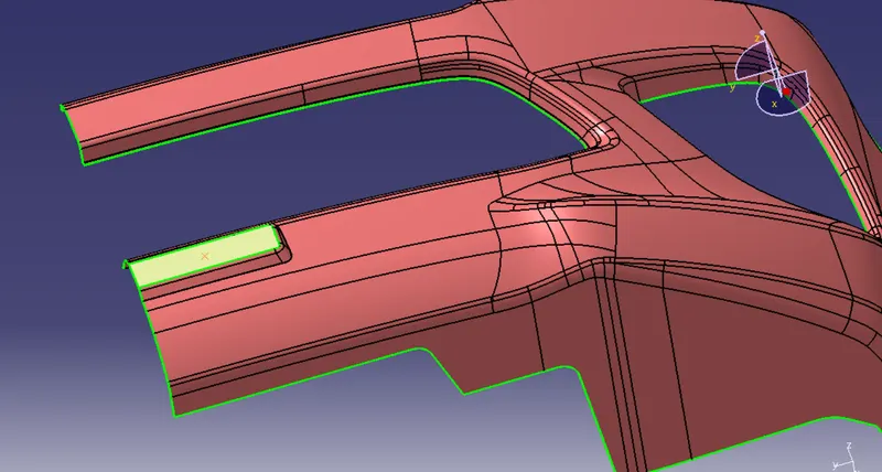
- Initially take the cad file in a an axis where all the edges are visible
- lets extract the flat surfaec of the number plate create a point and then create a line
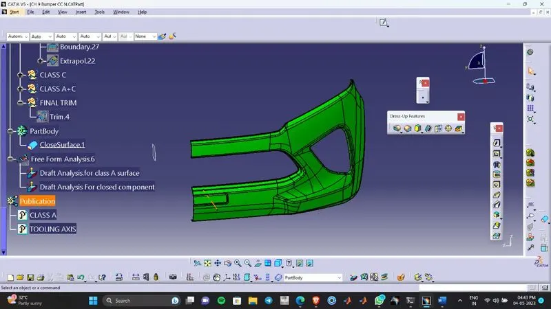
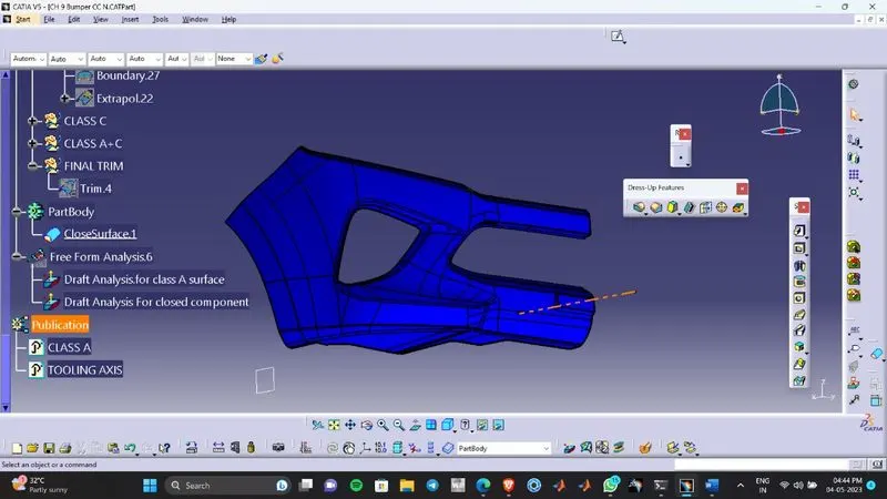
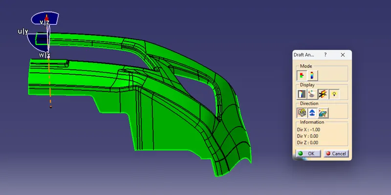
- Then check for draft analysis from insert menu
- Provide a miniumum draft of 3 degree, check whether the CLASS A is clearing or not
- So it is clearing so it is not a dummy tooling axis anymore , lets publish this as tooling axis
CREATION OF CLASS B
- Here we are going for Direct offset method instead extract and extrabolation
- create a geometrical set under construction as parent
- After offseting class A by 3mm we ll get a class B with missing fillets
- We are going to create 3 fillets one by one
- Before that we have to remove existing fillets using join (Sub elements to remove) and create from start to end
- After selecting all the fillets the ''check connectivivty'' in parameter shouls be unticked
- Here the surface is single now again we need to split the surface using multiple extract with point continuity
- Now all the surfaces are individually seperated
- Insert a new geometrical set patch 1 in class B
- Hide the join and 2 multi extract
- Now lets extrapolate 2 multiple extract surface
- Dont extrapolate from all the sides
- For doing the extrapolation we need boundaries use boundary option
- After extrapolation trim the surfaces and once we get the sharp edge measeure the fillet drom class B and provide the edge fillet 3.5mm
- Patch 1 is completed
- Create a geometricsl set under class B and name it as patch2
- Add tghe nect multiple extract and create the boundaries
- Extrapolate and trim
- Measure the fillets , if not getting use extract the perticular surface and create a pont and create a circle and measure the radius
- Radius = 1.3mm
- patch 2 is completed
- PATCH 3
- Create a geometricsl set under class B
- IF Ww try extraplotae it wont happen because of the shape of the surface
- splut the multiple extact using 2 multiple extarct (4+1 surafces)
- Extract the sharp edge surfaces
- untrim it to a rectangualr surfaces
- after extrapolating try to join (check connectivity ticked)
- use the intersection to find the overlapping
- Split the surfaces
- Join and split the extra surfaces using the zx plane
- Measure the fillet radi And provide the filletC SURFACE
- Create a gemoetrucal set under construction and name it as class C
- There are 9 edges havingtangential continuity So provide sweep
- Create a sweep single sweep is not possible beacuse fo the complex shape
- There are 3 surfaces created in parallel to tooling axis so provide 3 degree draft
- Create the boundary and then sweep3
- Make sure that the 3 ticks are checked in the bottom of the sweep ttol
- Finally 9 sweep is completed
- There is some extrapolation to do b/w 3 degree surface and 90 degree and b/w 3 and 3 surface
- After that do the trim
- Now join the trim with the other sweeps in to single sweep without the middle circular sweep
CREATION OF A+C SURFACE
- Create a geometrical set under construction
- Join the previous join , middle circular seep, and A surface with a merging distance of 0.003 mm
- FINAL TRIM
- Check whether B surface is intersecting with A+C , if not extrapolate B
- we havent got the intersection so create a geometrical set under class B
- Extrapolate each surfaces seperstely
- Dont go for boundaries a nd the extrapoltaion do it alternatively
- After extrapolation publish extrapolation B surafece
- NOW insert a new geometrical set final trim and trim A+C suraface with B
CLOSED SURFACE
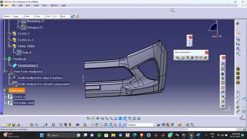
After getting final trim change the workbench to part design and insert a part body
use the closed surface to create a closed component
DRAFT ANALYSIS FOR CLOSED COMPONENT
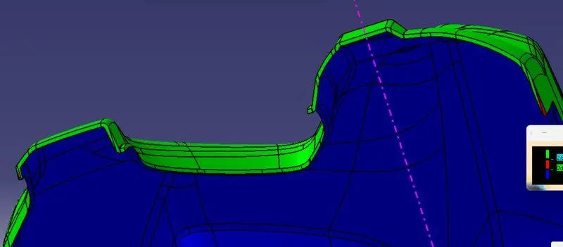
Open the draft analysis and use the compass and select inthe surface check whether class A and C is clearing if not reduce the value upto 2.8
publish the bumber solid