Week 9 Challenge
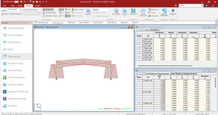
1. Design of dual slope (pitched) roof frame
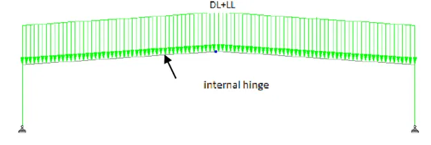
Design a 3 hinged pitched roof frame of a steel building. Assume no wind load acting on the walls and roof. Analyse the frame structure and draw bending moment, shear force and axial force diagrams of the frame. The slope of the roof is 1 in 10 and the roof is accessible for maintenance purpose (assume 75 kg/m2) only. Dead load on the roof are given below. Assume bay spacing as 5 m and frame width is 20 m. (Design code as per AISC:ASD. No seismic load consideration required)
Weight of roofing sheet = 5kg/m2
Weight of purlins + tertiary members = 25 kg/m2
Procedure:
- Open Staad
- Create the model structure of file and open it.
- Define and assign the nodes and beams as per ggiven data of structure.
- Assign properties of structure such asa tappered section and beta angles for columns.
- Create and design the support to columns and internal hinge.
- Add loading such as load case details as per given dead load and live load.
- Add load combination such DL+LL
- In loading we assign self weight,member load as per given data.
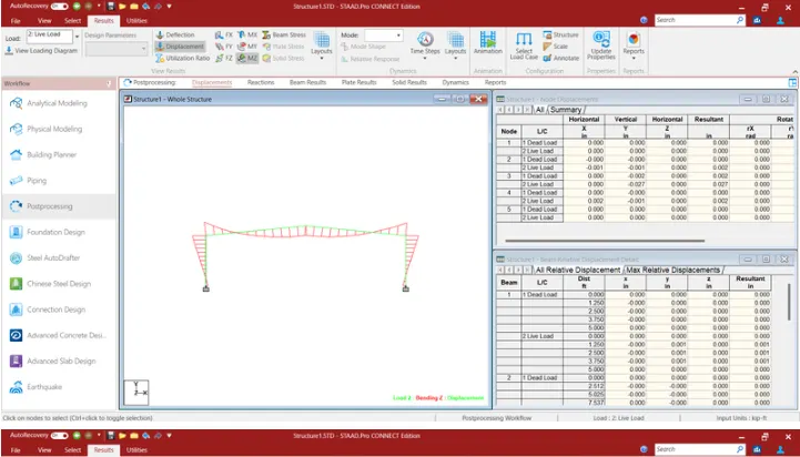
- Go to analysis and perform analysis.
- After that go to design use AISC:ASD code in options.
- Add design parameters and apply on the strcuture.
- In commands use steel take off and check codes apply on structure.
- Check utility ratio is less than 1 otr not.
- Do some trial error properties after we get proper section whose utility ration is less than 1.
- Check the bending moment diagram,shear force diagram and axial force diagram.
- Check heteher the section is passed or failed in design
2. Draw Bending Moment diagram for following Frame using STAAD.Pro
Figure 1)
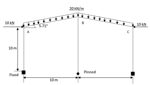
Given
Supports are fixed nd pinned
Angles of slopes-5.71 degrees.
Width of frame-20m
Height of end column- 10m
Height of mid column- 10 tan 5.71-1m
Height of mid column- 10+1=11m
Loading udl= 20 KN/m
Point load- 10KN
Procedure:
- Create frame model on staad.
- Assign properties to beams and columns.
- Assign the loading to section of member.
- Run the analysis.
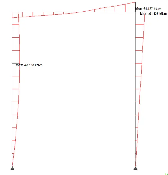
- Check the bending moment diagram.
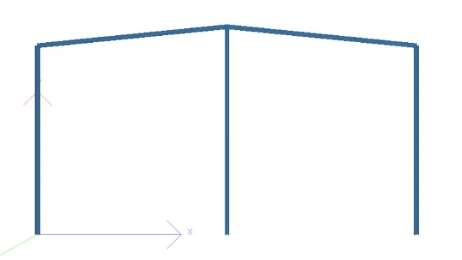
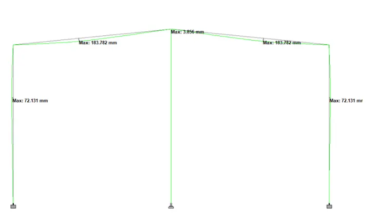
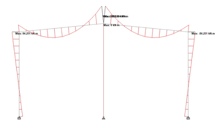
Figure 2)
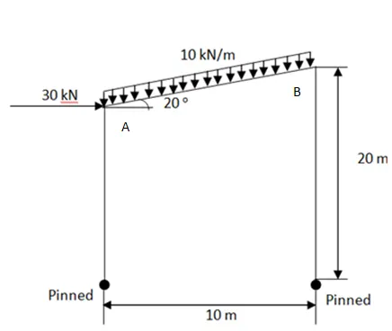
Given:
Supports are pinned
Angles of slopes-20 degrees.
Width of frame-10m
Height of end column- 20m
Height of mid column- 10 tan 20=3.64m
Height of mid column- 20-3.64=16.36m
Loading udl= 10 KN/m
Point load- 30KN
Procedure:
- Create frame model on staad.
- Assign properties to beams and columns.
- Assign the loading to section of member.
- Run the analysis.
- Check the bending moment diagram.
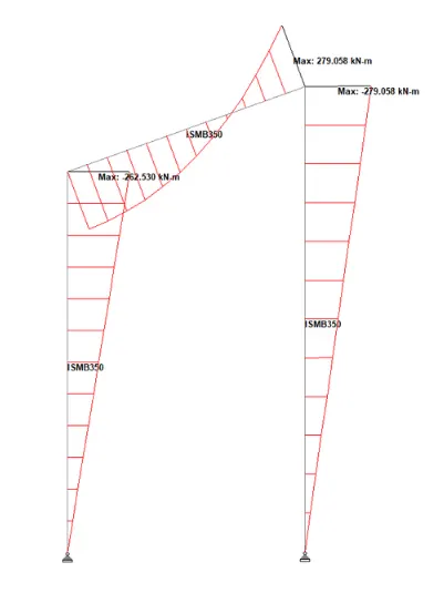
Figure 3)
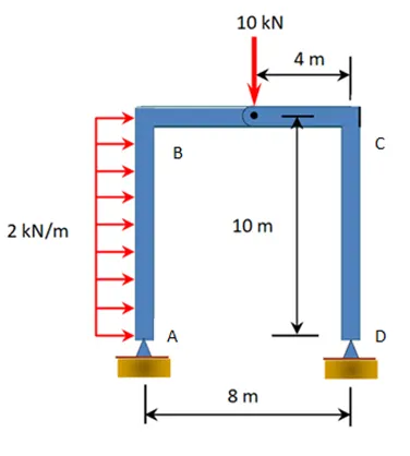
Given:
Supports are hinged.
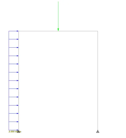
Width of frame=8m
Height of end column=10m
Loading UDL= 20KN/m
Point load= 10 KN
Procedure:
- Create frame model on staad.
- Assign properties to beams and columns.
- Assign the loading to section of member.
- Run the analysis.
- Check the bending moment diagram.