Drafting of various geometries using Chamfer, Fillet tool in AutoCad
Aim: to draw the given skecthes using AutoCAD software.
Procedure:
Drawing 1:
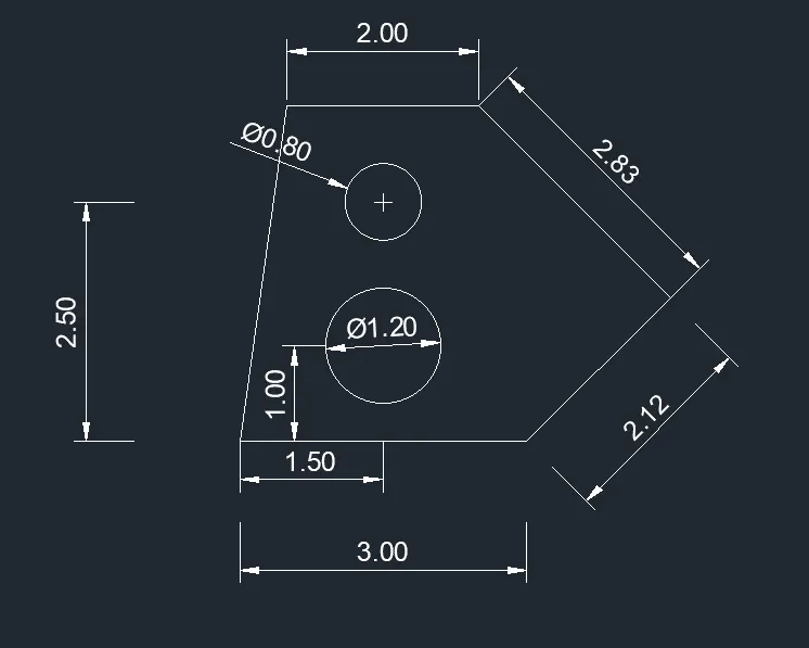
- Open autocad software click on wizard the advance settings and set the units as decimal.
- Set the angle in degree with base angle as east and mark the angle direction in anticlockwise.
- Take line command and from a random point draw 3 units line then @2.12<45,@2.83<135 then a 2 unit straight line and close.
- Using the offset command offset 3 units line to 1 and 2.5 units.
- Using the circle command: from midpoint of 3 unit line draw two circles at 1 and 2 units with a diameter of 1.20 and 0.80 units.
- Trim the extra lines.
Result: the geometry is drawn.
Aim: to draw the given skecthes using AutoCAD software.
Procedure:
Drawing 2:
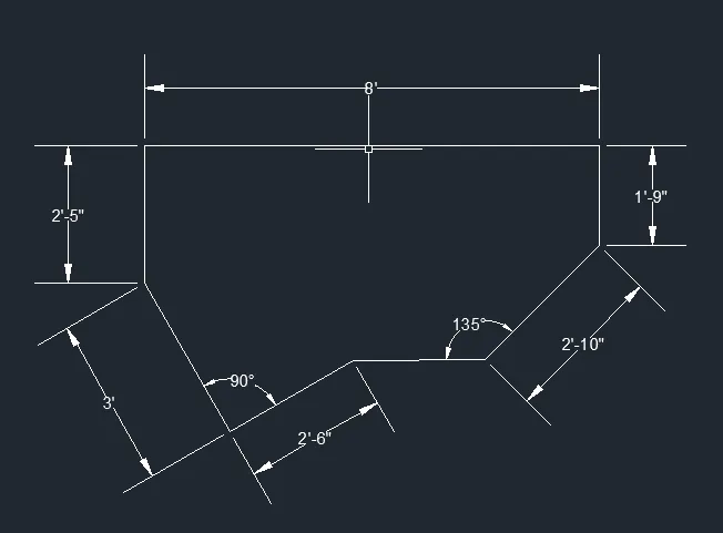
- Open autocad software click on wizard the advance settings and set the units as architechture.
- Set the angle in degree with base angle as east and mark the angle direction in anticlockwise.
- Draw line of length 2'6" at an angle of 210 degree by using line command.
- With angle as 90 degree draw another line of length 3'.
- With ortho on draw a line of length 2'5" vertically.
- Draw another line of 8' horizontally then 1'9" vertically downwards.
- Then use line command a draw line of 2'10" from the last point of 1'9" meeting the horizontal at an angle of 135 degree.
Result: the geometry is drawn.
Aim: to draw the given skecthes using AutoCAD software.
Procedure:
Drawing 3:
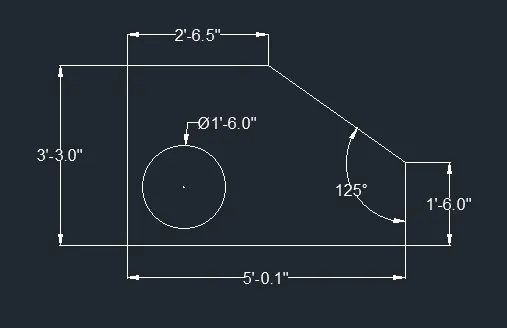
- Open autocad software click on wizard the advance settings and set the units as engineering.
- Set the angle in degree with base angle as east and mark the angle direction in anticlockwise.
- Using line command draw 2'6.5" in -x axis,3'3" in -y axis,5'0.1" in + x axis,1'6" in + y axis and close.
- Using the offset command: offset 3'3" line at a distance of 1'3" and 5'0.1" at a distance of 1'6"
- Using circle command: draw a circle of diameter 1'6" from the centre of offsetted line.
- Trim the extra lines using trim command.
Result: the geometry is drawn.
Aim: to draw the given skecthes using AutoCAD software.
Procedure:
Drawing 4:
- Open autocad software click on wizard the advance settings and set the units as decimal with precision 0.00 keeping ortho on.
- Set the angle in degree with base angle as east and mark the angle direction in anticlockwise.
- Using line command draw 3 unit line in + x axis,0.50 unit in - y axis,2.50 unit in + x axis,2.50 unit in + y axis,2.00 unit in - x axis,3.00 unit in + y axis,2.50 unit in - x axis,2.00 unit in - y axis,3.00 unit in - y axis and close.
- Do the dimensioning as required.
Result: the geometry is drawn.
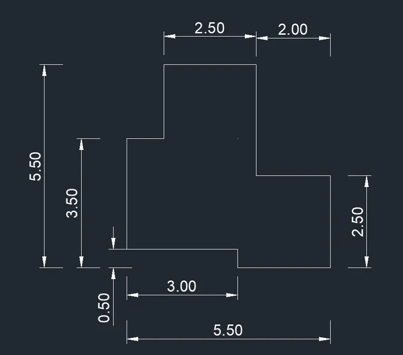
Aim: to draw the given skecthes using AutoCAD software.
Procedure:
Drawing 5:
- Open autocad software click on wizard the advance settings and set the units as decimal with precision 0.00 keeping ortho on.
- Set the angle in degree with base angle as east and mark the angle direction in anticlockwise.
- Using line command: draw 6 units vertical line then 11.50 horizontal and the gain 6 unit vertical and 11.50 unit horizontal.
- In object snap setting keep midpoint,centre,intersection and geometric centre on.
- Using command circle: draw a circle at the centre with diameter 3 units.
- Using offset command: offset 6 unit line at a distance of 3 units on both the sides and offset 11.50 unit line at a distance of 3 units.
- Using circle command: Draw the concentric circles at the intersection of the offsetted line of diameter 1 and 2 units on both sides.
- Trim the extra line using trim command.
Result: the geometry is drawn.
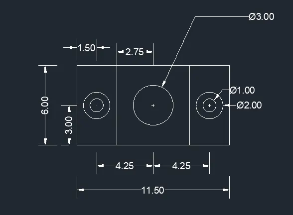
Aim: to draw the given skecthes using AutoCAD software.
Procedure:
Drawing 6:
- Open autocad software click on wizard the advance settings and set the units as decimal with precision 0.00 keeping ortho on.
- Set the angle in degree with base angle as east and mark the angle direction in anticlockwise.
- Using line command : draw 1.5 unit horizontal and vertical on both sides.
- Using offset command: offset 1.5 unit line to 0.5 unit
- Using divide command: divide 1.5 unit into 3 segments.
- Using line command : join the divided lines.
- Keep the extension on in object snap setting.
- Using line command: draw 2 unit line and 1.5 unit line and 0.5 unit horizontal on top and in vertical 0.5 unit on bottom and join the slant height.
- For the top figure using line command 2 unit horizontal and 1.5 unit vertical on both sides.
- Using offset command: offset 1.5 unit line to 0.5 unit.
- Using divide command: divide 1.5 unit into 3 segments.
- Using line command : join the divided lines.
Result: the geometry is drawn.
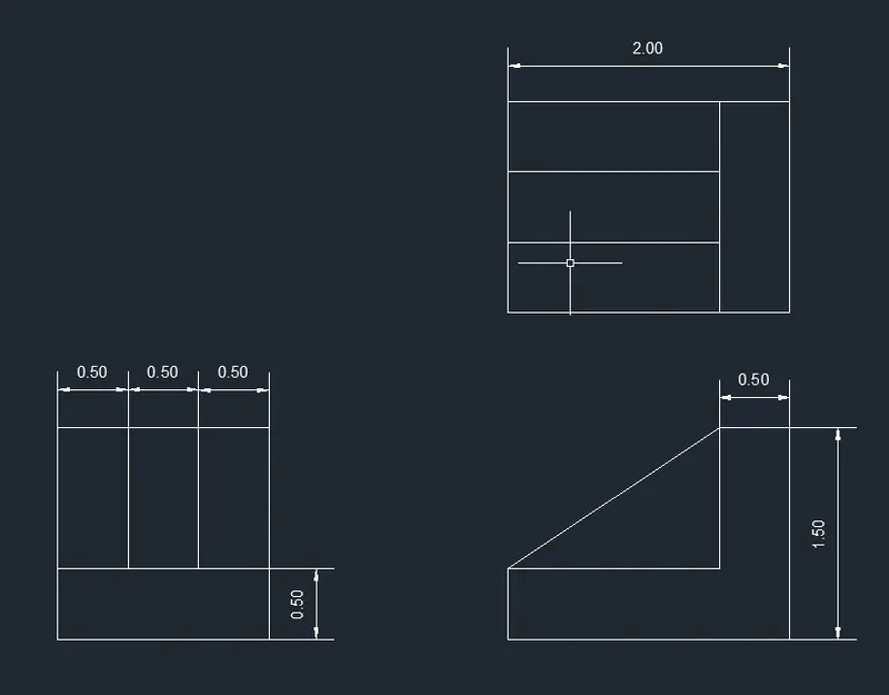
Aim: to draw the given skecthes using AutoCAD software.
Procedure:
Drawing 7:
- Open autocad software click on wizard the advance settings and set the units as decimal with precision 0.00 keeping ortho on.
- Set the angle in degree with base angle as east and mark the angle direction in anticlockwise
- Using line command: draw 210 unit horizontal line and 100 unit vertical line and 75 unit vertical on right side.
- Now as arc 1 has a radius of 35 units we draw a line of 70 unit on left side and arc 2 has a radius of 25 unit we draw a line of 50 unit on right side.
- Using circle command: from the midpoint of 70 unit line on left side draw a circle of diameter 50 units and 30 units on right side.
- Using the offset command: offset 210 unit line at a distance of 60 units.
- Using fillet command: Fillet the top right to 15units radius and top left to 15 unit radius.Fillet the inner left and right to radius of 6 units.
- Using offset command: offset 210 unit line to 10 units and 100 and 75 unit line to 20 units.
- Using rectangle command: make a rectangle of length 70 units and width 30 units from offsetted line on both sides.
- Trim the extra line using trim command.
Result: the geometry is drawn.
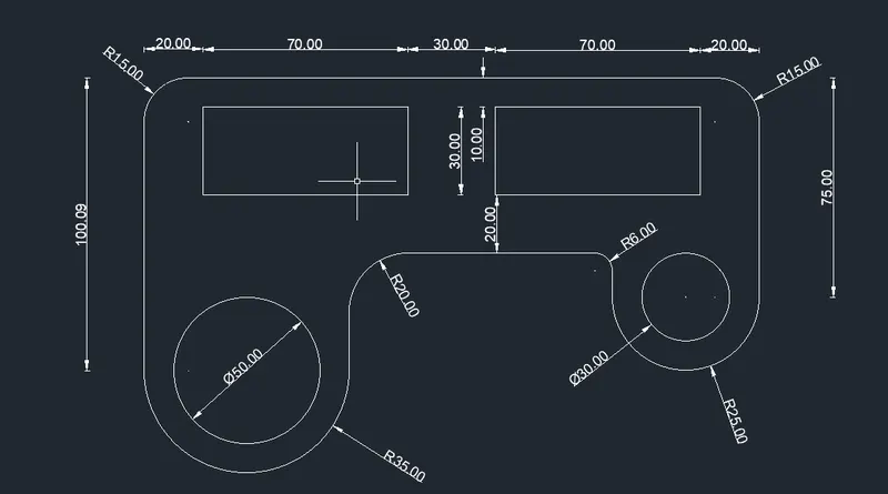
Aim: to draw the given skecthes using AutoCAD software.
Procedure:
Drawing 8:
- Open autocad software click on wizard the advance settings and set the units as decimal with precision 0.00 keeping ortho on.
- Set the angle in degree with base angle as east and mark the angle direction in anticlockwise.
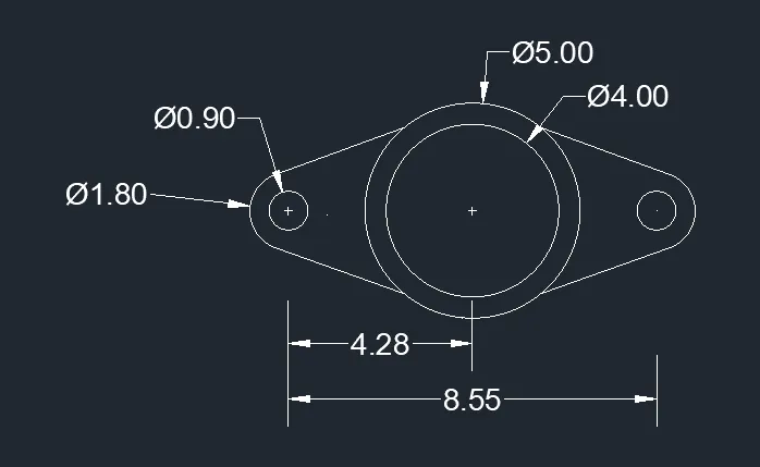
- Using circle command: draw concentric circles of diamter 5 units and 4 units.
- Using line command: From the centre point of circle draw 4.275 line on both sides.
- Using circle command: Draw a circle of diameter 0.90 units on both sides.
- Using arc command: from start,end and radius draw an arc of radius 0.90 units on both sides.
- Using command line join the lines to the arc.
Result: the geometry is drawn.
Aim: to draw the given skecthes using AutoCAD software.
Procedure:
Drawing 9:
- Open autocad software click on wizard the advance settings and set the units as engineering with precision 0.00 keeping ortho on.
- Set the angle in degree with base angle as east and mark the angle direction in anticlockwise.
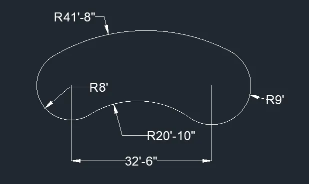
- Using line command: draw a 32'6" horizontal line.
- Using command circle: draw a circle of radius 8' on left side of line and radius of 9' on right side of line.
- Using arc command: from start,end and radius draw a arc of 41'8" on top and 20'10" on bottom.
- Trim the extra line using trim command.
Result: the geometry is drawn.
Aim: to draw the given skecthes using AutoCAD software.
Procedure:
Drawing 10:
- Open autocad software click on wizard the advance settings and set the units as engineering with precision 0.00 keeping ortho on.
- Set the angle in degree with base angle as east and mark the angle direction in anticlockwise.
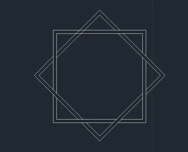
- Using the rectangle command create a rectangle of length =5 units and width=5 units.
- Using offset command: take a offset of 0.2 units outside the rectangle and specify the distance as 0.2 units.
- Create another rectangle of same size as created earlier.
- Using rotate command: rotate the square by specifying the base point and roate it by 45 degree.
- By using object snap place the second square on the centre of first square.
Result: the geometry is drawn.
Aim: to draw the given skecthes using AutoCAD software.
Procedure:
Drawing 11:
- Open autocad software click on wizard the advance settings and set the units as engineering with precision 0.00 keeping ortho on.
- Set the angle in degree with base angle as east and mark the angle direction in anticlockwise.
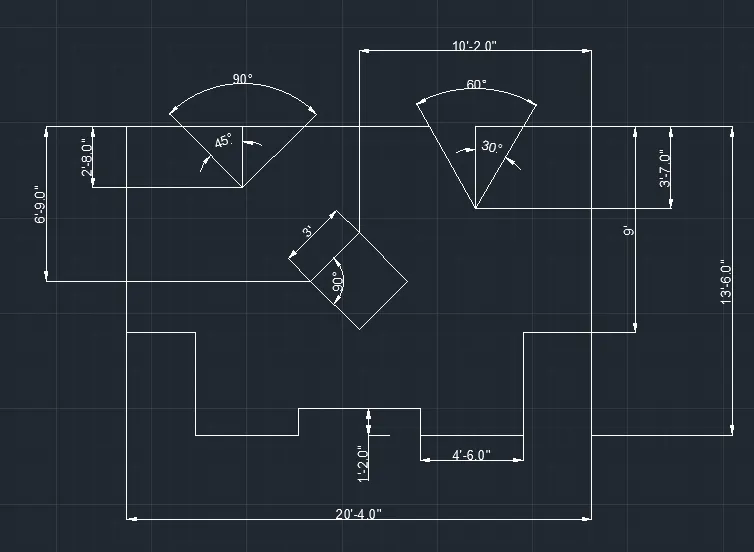
- Using line command: Draw 10'2" horizontal line,9' vertical line,3' horizontal line,4'6" vertical and horizontal line and 1'2" vertical line.
- Using mirror command: mirror the above lines at center axis.
- Using offset command: offset the 20'4" to a distance of 6'9" and 13'6" to a distance of 10'2"
- Using rectangle command: draw a rectangle of length and width 23 from the centre of offsetted line.
- Using rotate command: rotate the rectangle by 45 degrees.
- Using offset command: offset 20'4" line to a distance of 2'8" with polar tracking on and draw an angle of 90 degrees.Offset 20'4" line to a distance of 3'7" with polar tracking on draw an angle of 60 degrees.
- Trim the extra lines using trim command.
Result: the geometry is drawn.