Week 9 Challenge
1. Design of dual slope (pitched) roof frame
Aim & Introduction- To Design a 3 hinged pitched roof frame of a steel building, Analyse the frame structure and draw bending moment, shear force and axial force diagrams of the frame.
Given data- The slope of the roof is 1 in 10 and the roof is accessible for maintenance purpose (assume 75 kg/m2) only.
Assume bay spacing as 5 m and frame width is 20 m. (Design code as per AISC:ASD. )
Weight of roofing sheet = 5kg/m2
Weight of purlins + tertiary members = 25 kg/m2
Procedure in detail -
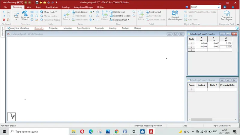
Usiung Node command plot (0,0 0) & (10,0,0)
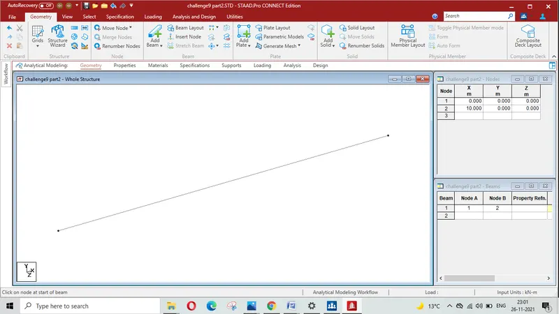
Using Add beam command join two Nodes
Using Transition Repeat draw a beam at Y =5m ( Assuming height of column)
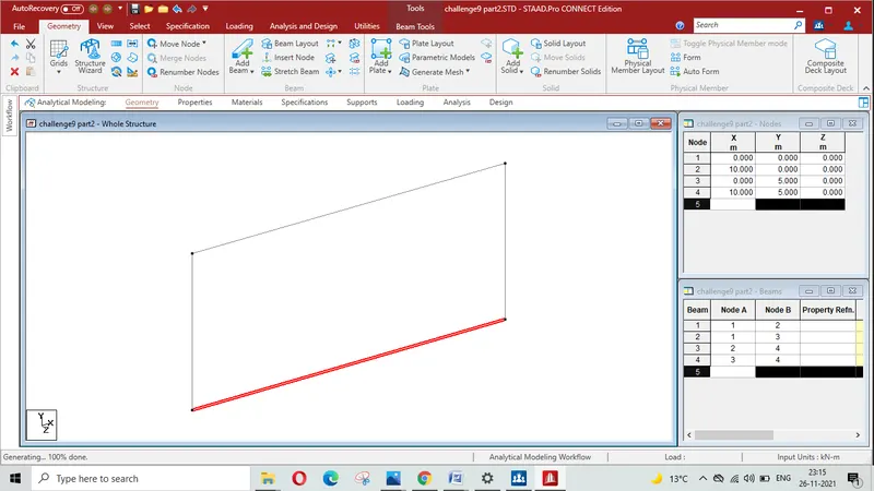
Now delete the bottom beam after selecting and using delete command
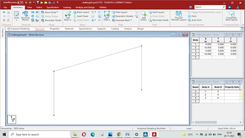
Delete one column on right side
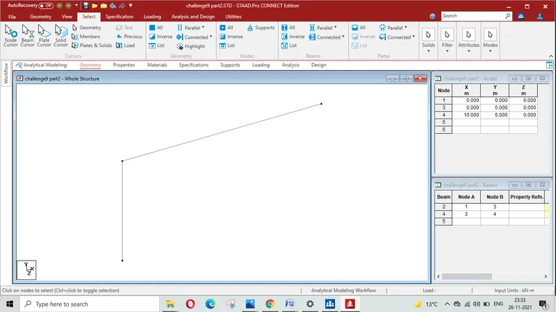
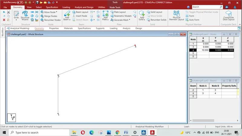
Move Node No # 4 vertically by 1 m for maintaining slope of 1:10
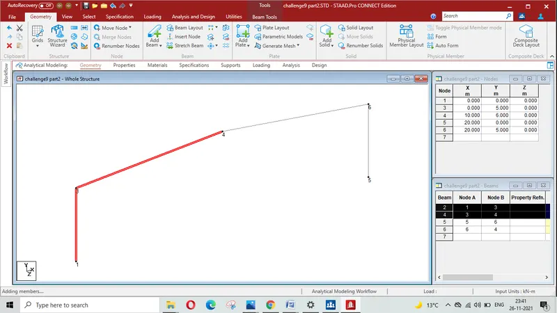
Using Mirror command complete the frame
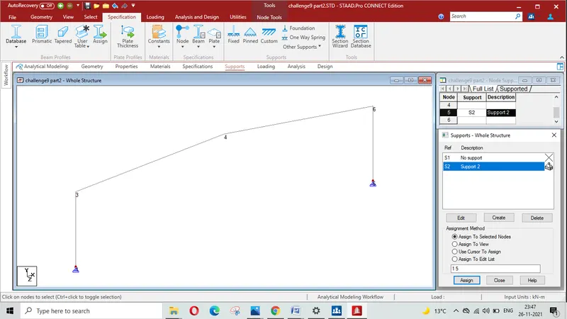
Add Hinge support at two columns using Support command
Assigning ISMB 400 to both thed Columns ( Property Assignment)
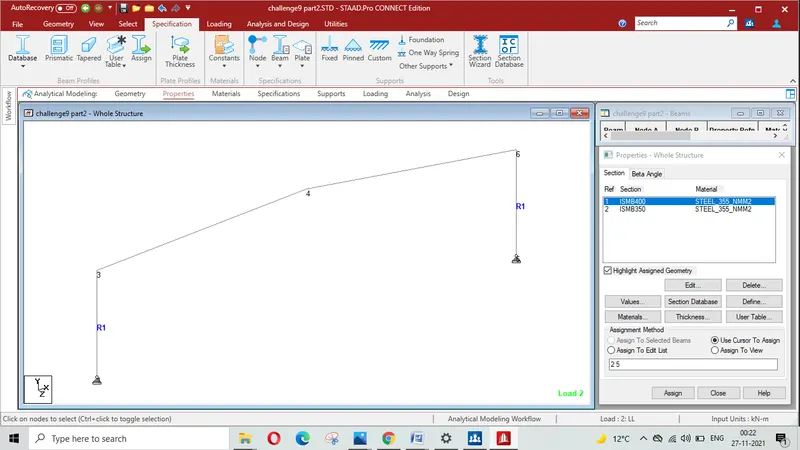
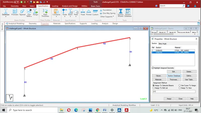
Assigning ISMB 350 to the Rafter ( Property Assignment)
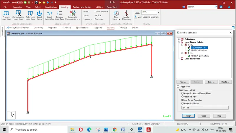
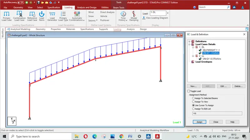
Applying Dead Load & Live load on the Rafter as per calculation given below -
a) Self weigh
b) Wt of Roffing sheet @ 5 Kg/SqM + Wt of Purlin & Tertiary members @ 25 Kg/SqM
Thus Total Dead Load on rafter will be (25+5)x Bay width wich is 5m =150 Kg/SqM= 1.5 KN/m ( As given frame is main frame)
Live Load = 75 Kg/Sqmx 5 = 0.375 KN/m
Dead load :Self Weight+ Wt of Roffing sheet +Wt of Purlin & Tertiary members
Live Load-
Load combination: 1.5 DL+1.5 LL
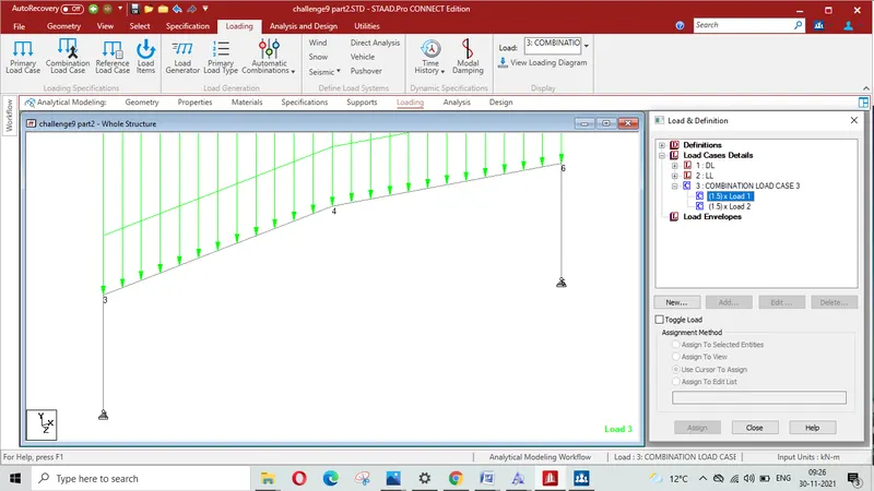
Analysing the model/structure using Run Analysis command
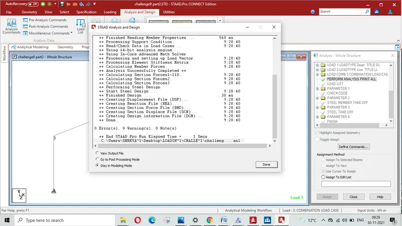
Model is analyse with 0 Errorr, 0 Warning & 0 Note
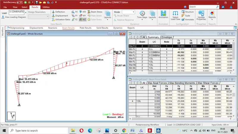
Bending Moment diagram is given below
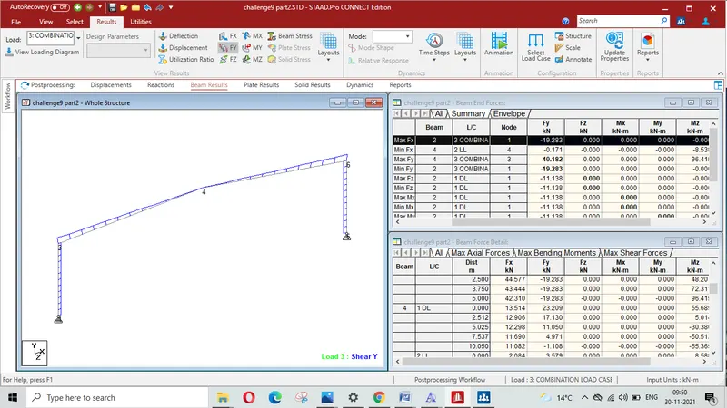
Shear Force diagram is as given below-
Axial Force diagram is as follows-
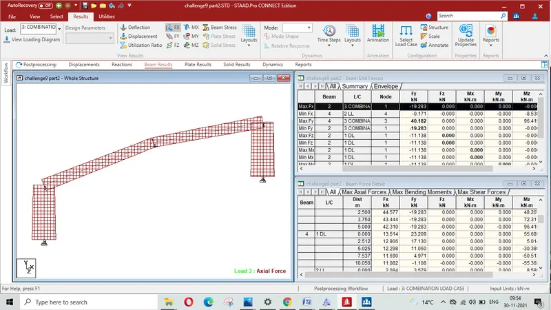
Result:
It is concluded that the given model is analyse successfully with 0 Error 7 0 warning without any Note and BMD, SFD & Axial Force diagrams are drawn as above. The Staad Pr0 file is also attached for Run analysis
Q2. Draw Bending Moment diagram for following Frame using STAAD.Pro
Figure 1)
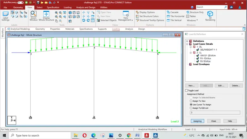
Aim & Introduction- To draw Bending Moment Diagram of the given model with following given data-
Span = 20 m
Height of the column = 10 m
Slope = 5.71 Degree
Support Conditions = Fixed support at two exterior columns & Pinned support at middle column
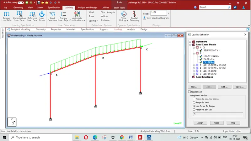
Loading = 20 KN/m UDL on Rafter & 10 KN Nodal load along X direction at node A & C
Procedure- First of all model is prepared with given data as shown below-
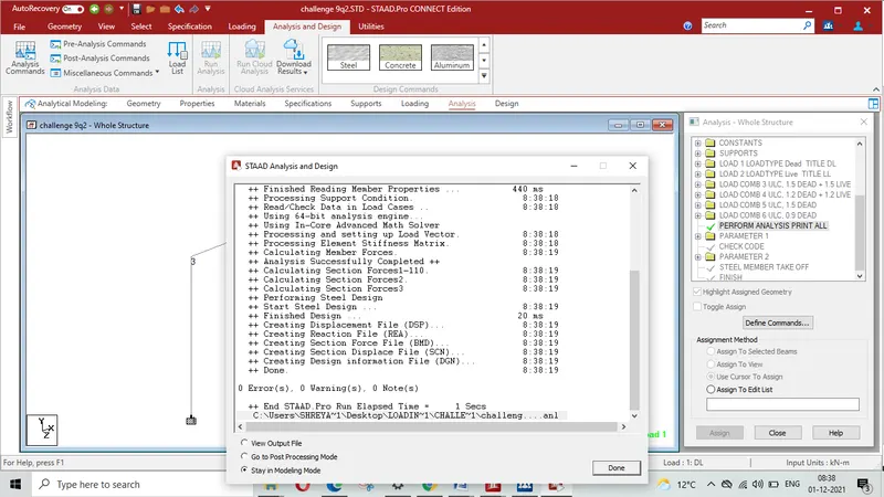
Run analysis command has been performed successfully without any Error ,Warning & Note as shown below in the print screen
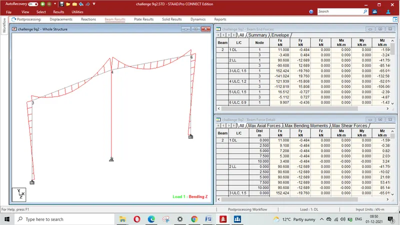
Bending Moment Diagram of the model for given loading is as shown below in the print screen-
Staad pro model file is attached herewith-
Result : It is concluded that Bending Moment Diagram is as drawn above
Q2 (Fig-2)
Aim & Introduction- Bending Moment Diagram of given frame is required to be drawn using Staad.Pro software ,
Given data for frame: Mono pitched roof frame with span= 10 m
Column height on one side =20 m
Slope angle= 20 Degree
Columnt height of other column = 20 m - 10x tan(20degree) = 16.603
Support Conditions: Both columns are Hinged supported
Loading : UDL of 30 KN/m on pittched roof & 10 KN of Nodal load at the node of shorter column and beam
Procedure : Frame with given data is created using, Loading is assigned as per given detaials and member properties are also assigned .
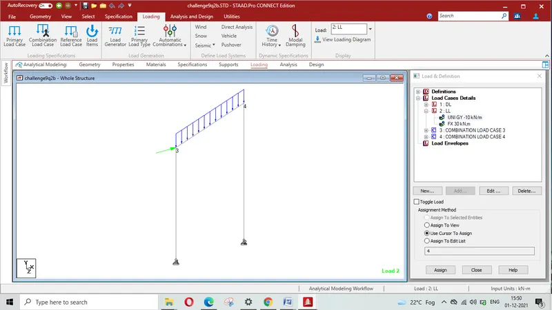
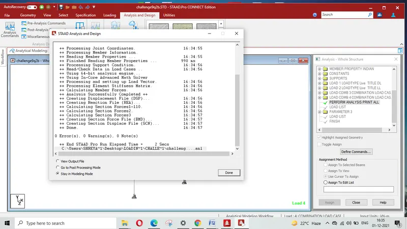
Run analysis command has been performed successfully without any Error ,Warning & Note as shown below in the print screen-
BMD is as given below which has been captured as print screen in Post processing-
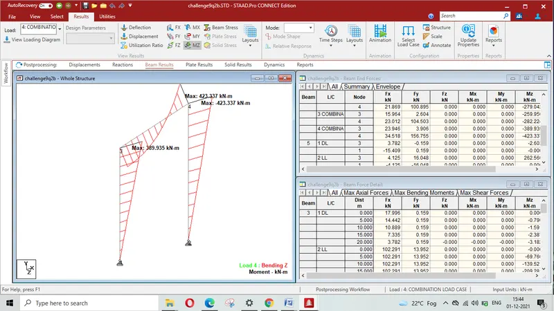
Result: Bending Moment Diagram is shown above for most critical load combination ( case-4). Thus it is concluded that Bending Moment is max for load combination -4. Staad.Pro file is also attached for executing various coomand.
Q2 (Fig-3)
Aim & Introduction- Bending Moment Diagram of given frame is required to be drawn using Staad.Pro software ,
Given data for frame: Frame with span= 8 m
Column height on one side =10 m
Support Conditions: Both columns are Hinged supported and also hinged at the center center of beam there is hinge
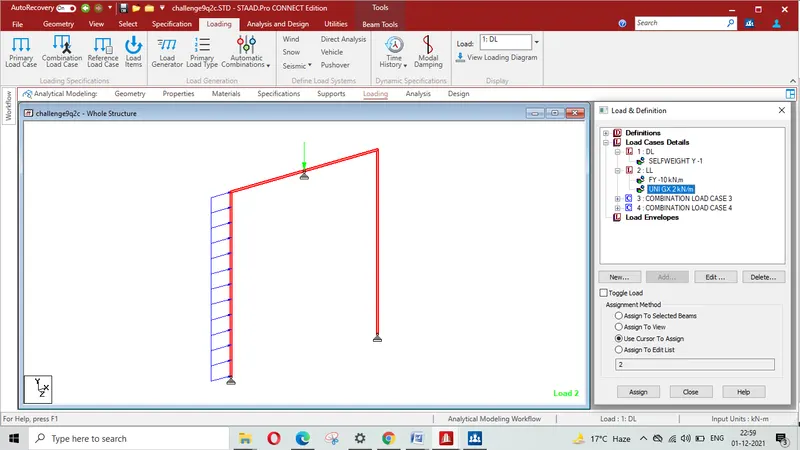
Loading : Nodal load of 10 KN/m at hinged support of roof beam & UDL of 10 KN/m on the column on left side alonf X axixs.
Procedure : Frame with given data is created using, Loading is assigned as per given detaials and member properties are also assigned .
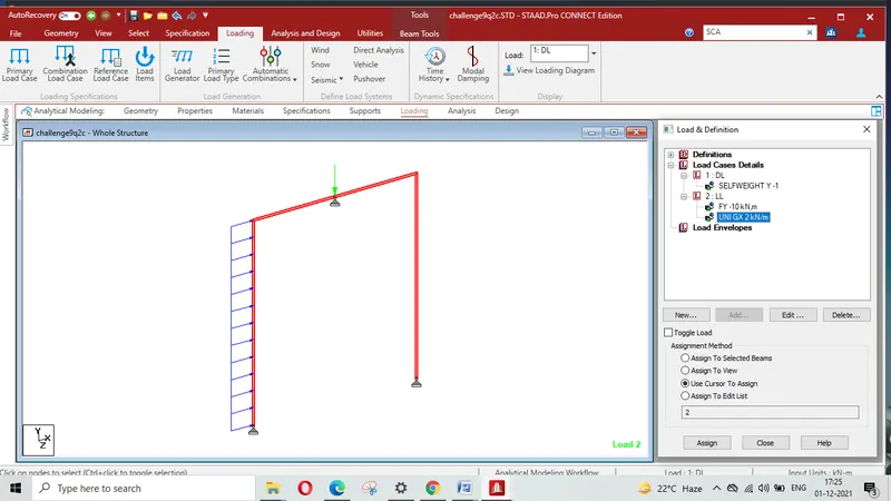
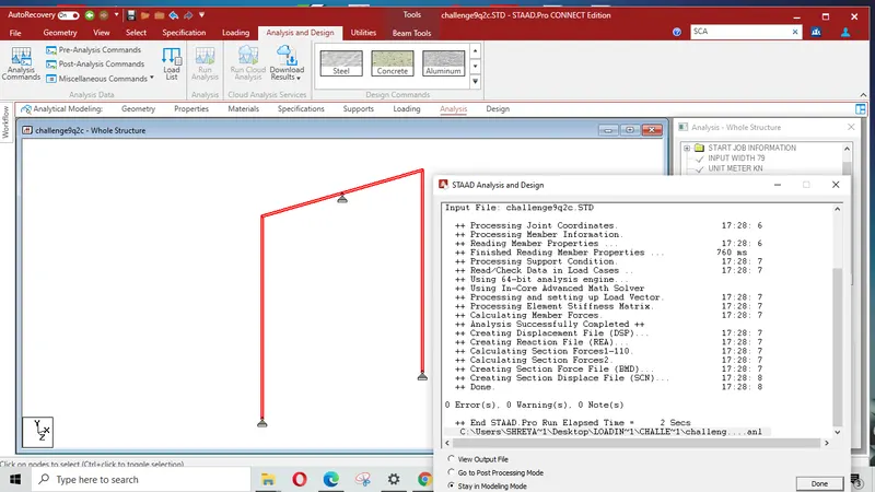
Run analysis command has been performed successfully without any Error ,Warning & Note as shown below in the print screen-
BMD is as given below which has been captured as print screen in Post processing-
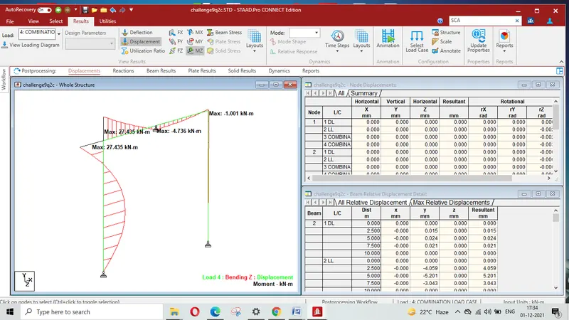
Result: Bending Moment Diagram is shown above for most critical load combination ( case-4). Thus it is concluded that Bending Moment is max for load combination -4. Staad.Pro file is also attached for executing various coomand.
3. Deflection of a frame, present result from STAAD.Pro
1) Aim & Introduction- Lateral deflection at point A and vertical deflection at mid section of Beam between B & C from figure-1 in previous chaalenge i.e. challenge-2 ( Fig-1) are required to be determined.
Procedure-
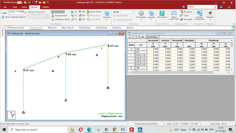
With the model of challenge-2 ( Fig-1) using Run Analysisi command in the Analysis and Design option then in the Post Processing option displacement command for load combination case-3 give the maximum deflection as shown below-
Deflection at A is 0.727 mm as shown in the print screen given below-
Max deflection at mid point of beam between B & C is 22.626 mm as shown below-
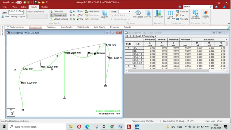
Staat.Pro file is already attached against Challenge-2 through which max deflection ( Load case-3) can be viewed using deflection command in the Post Processing after performing Run Analysis command in Analysis and Design.
Result: it is concluded that the deflection at point A = 0.727 mm & at mid point of beam between B & C is 22.626 mm
Q-3(2) Aim & Introduction- Lateral deflection at point A and vertical deflection at mid section of Beam between A & B from figure-1 in previous chaalenge i.e. challenge-2 ( Fig-2) are required to be determined
Procedure-
With the model of challenge-2 ( Fig-2) using Run Analysisi command in the Analysis and Design option then in the Post Processing option displacement command for load combination case-3 give the maximum deflection as shown below-
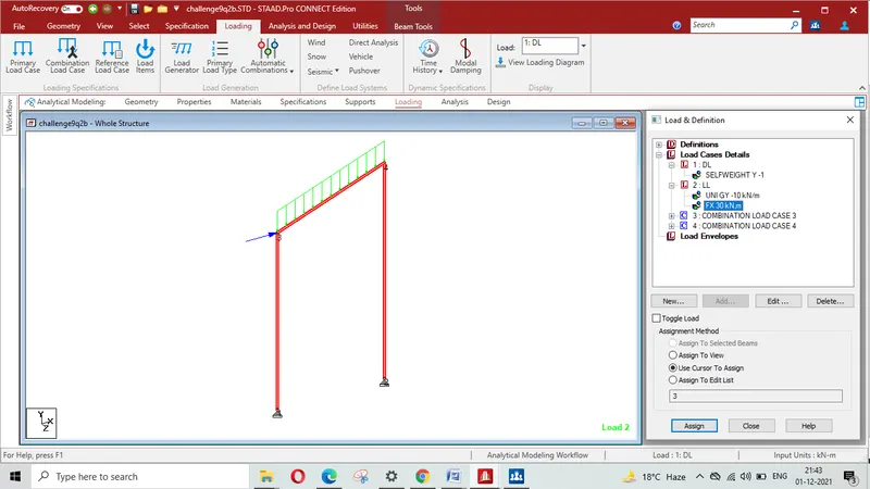
Deflection at A is 931.174 mm as shown in the print screen given below-
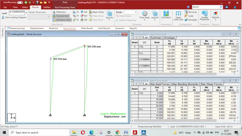
Max deflection at mid point of beam between A & B is 629.147 mm as shown below-
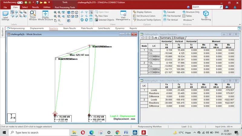
Result: it is concluded that the deflection at point A = 931.174 mm & at mid point of beam between B & C is 629.147 mm
Q-3(3) Aim & Introduction- Lateral deflection at point A a & B from figure-3 in previous chaalenge i.e. challenge-2 ( Fig-3) are required to be determined
Procedure-
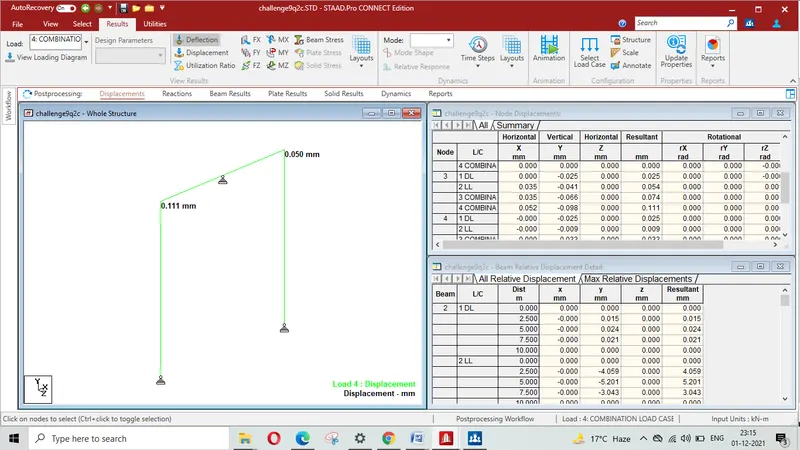
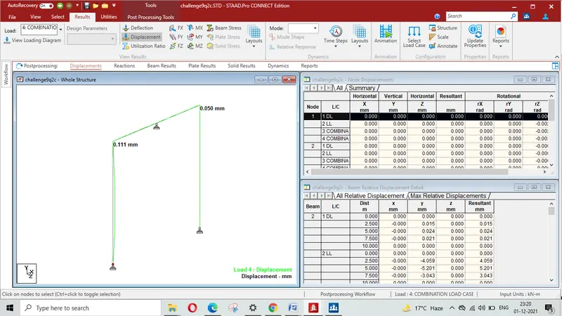
With the model of challenge-2 ( Fig-3) using Run Analysisi command in the Analysis and Design option then in the Post Processing option displacement command for load combination case-3 give the maximum deflection as shown below-
Deflection at A along X Axis = 0.052 , Along Y Axis = 0.098 mm and Resultant displacement is 0.11 mm as shown in the print screen given below-
Deflection at B along X Axis = 0.00 , Along Y Axis = 0.00 mm and Resultant displacement is 0.00 mm as shown in the print screen given below-
Result: it is concluded that the Ressultant deflection at point A = 0.11 mm & at B is 0.00 mm