Week 9 Challenge
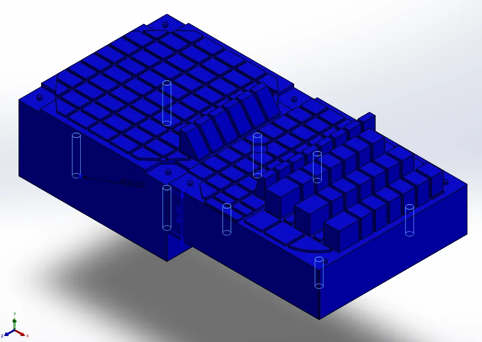
CPU fan case SLIDER and INSERTS:
INPUT:
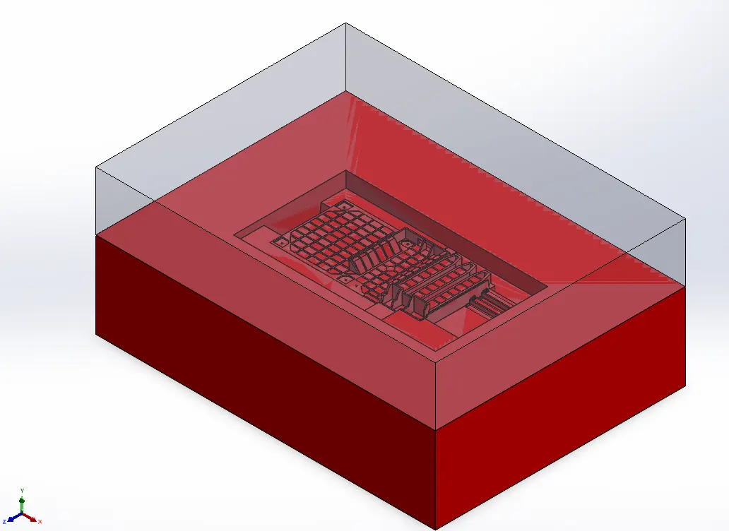
OUTPUT:
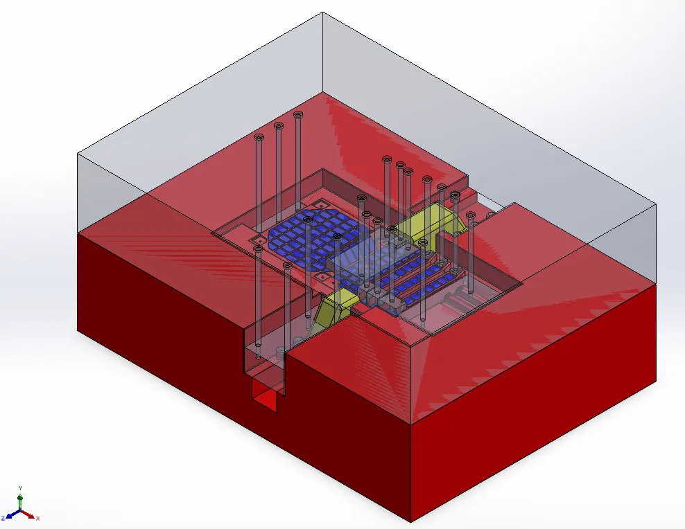
SLIDERS: Yellow
INSERTS: Blue
CORE: Red
CAVITY: Transparent block (originally in green)
Procedure for Sliders:
- For SLIDER01 in core block, sketch is done which surrounds the undercut part with hole.
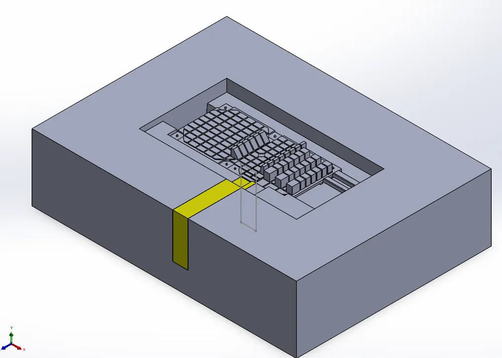
- Slider body (in yellow) is then further modified according to profile of hole required.
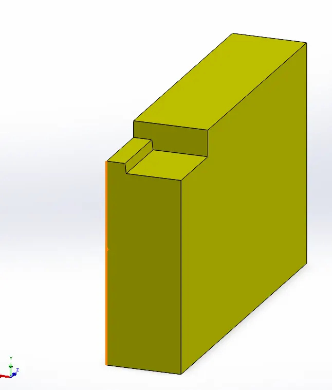
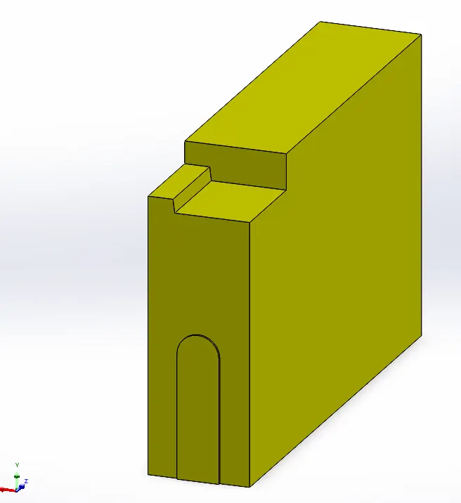
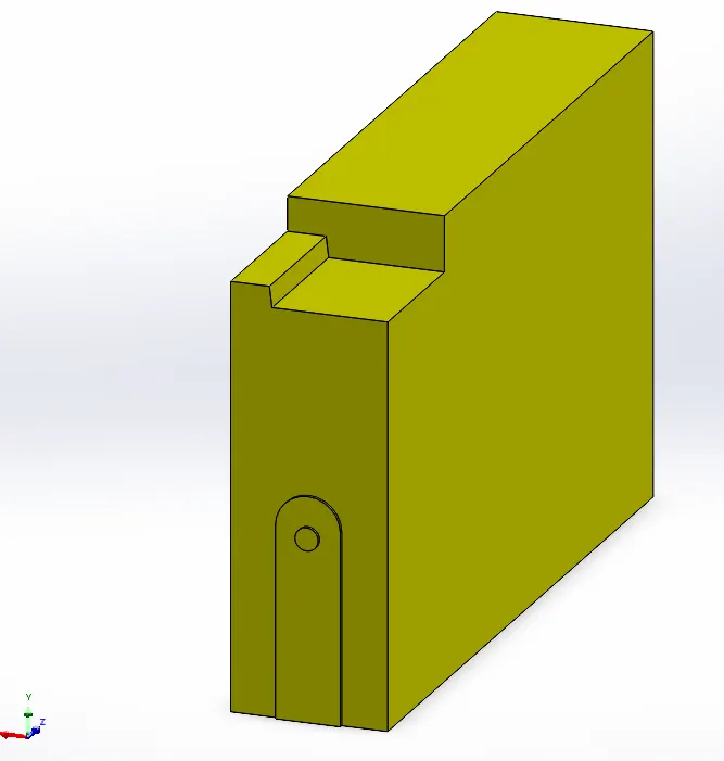
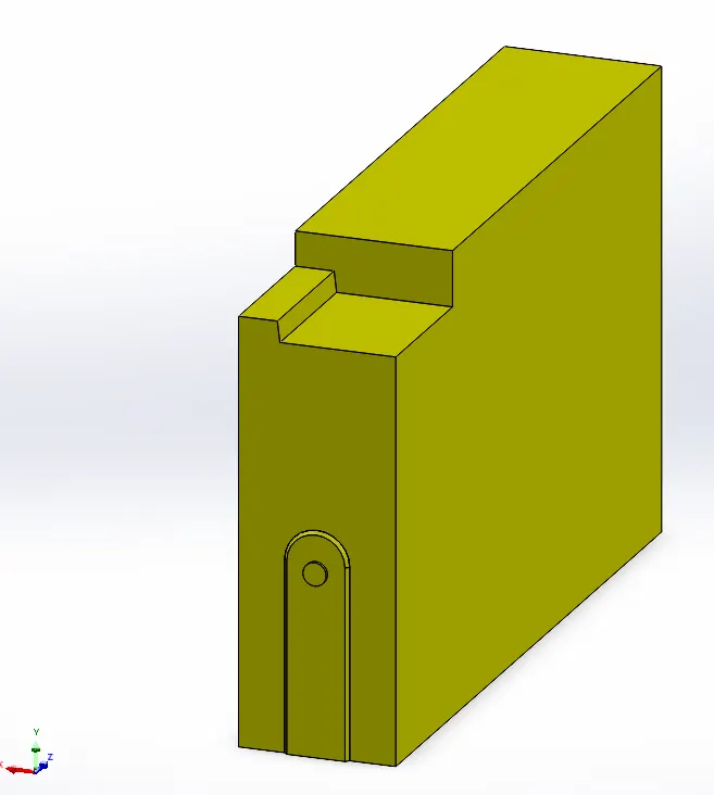
- Futher modification is done to obtained the required shape of slider.
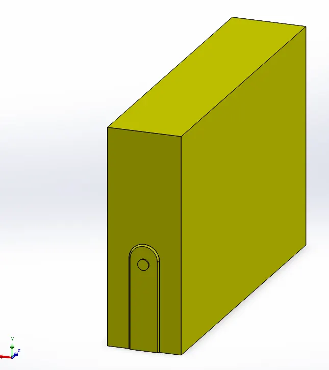
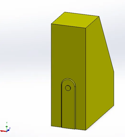
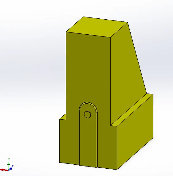
- Similar spaces are created to accomodate slider in core block.
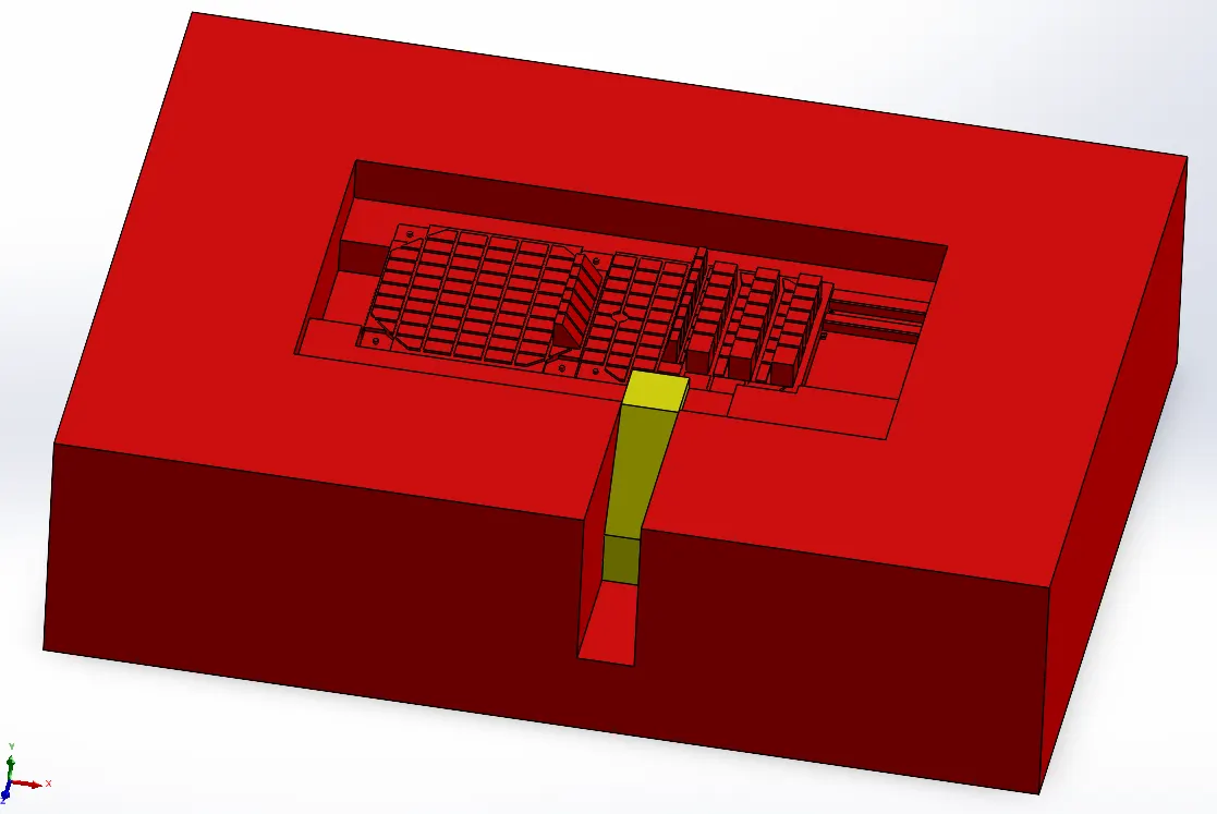
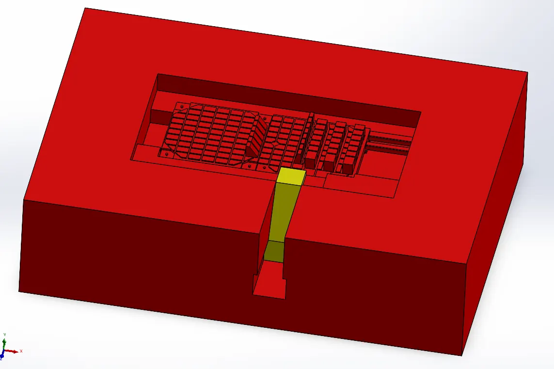
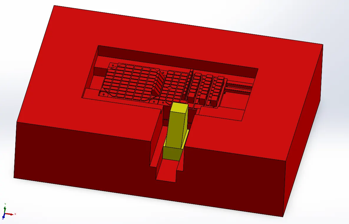
- Also reliefs were created on the sides parallel to tooling direction. So that metal to metal contact can be avoided at core and cavity interface.
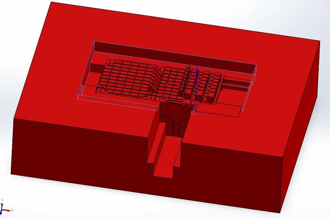
- Modifications are done for slider01 in cavity block also, which include importing slider01 body, creating extrude and removing area of slider using COMBINE command so that slider can be snugly fitted into it.
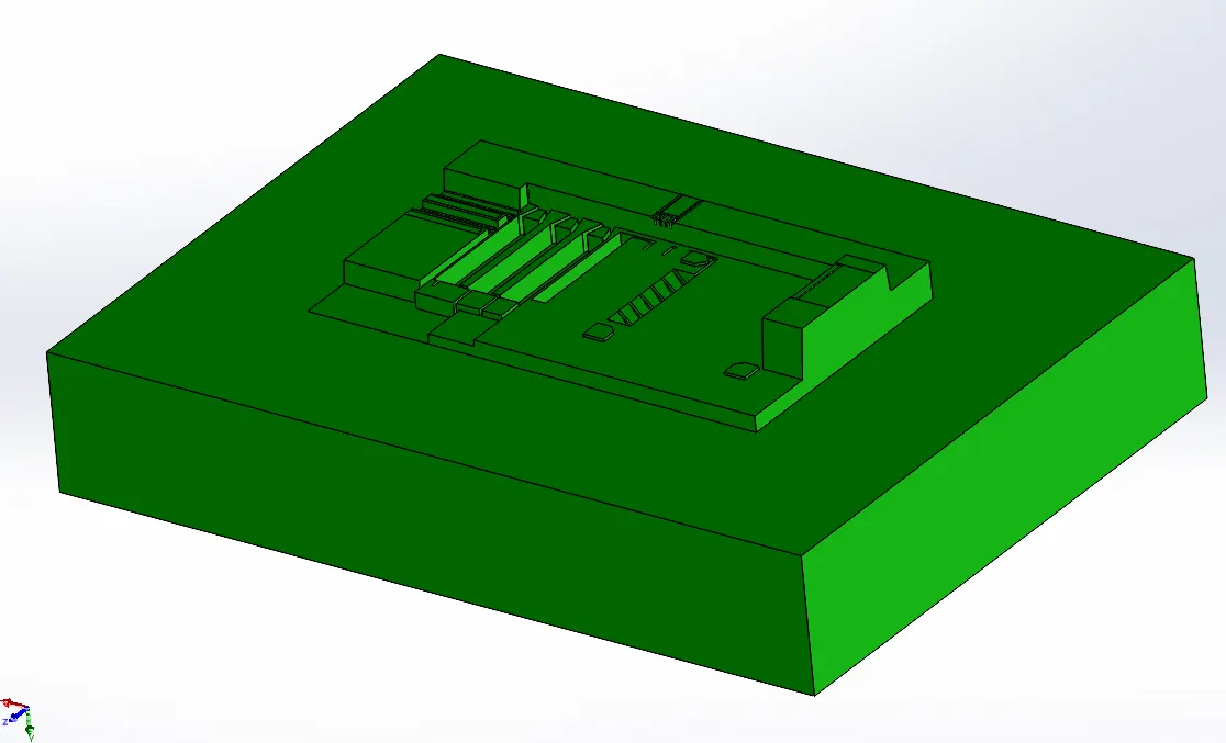
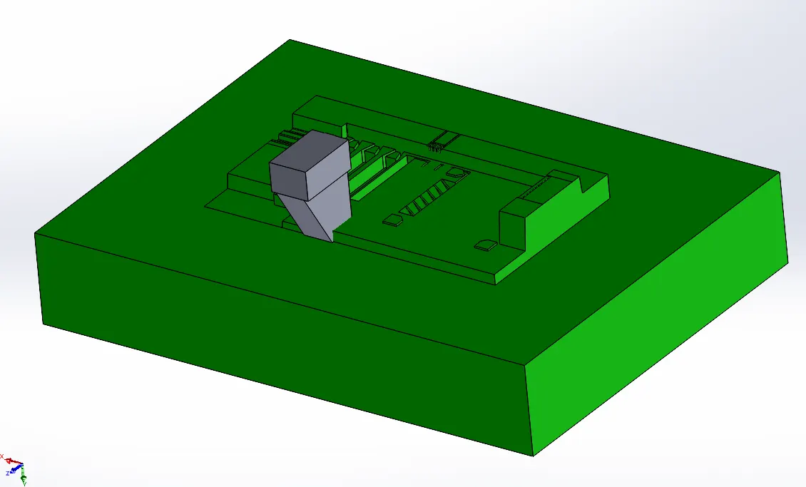
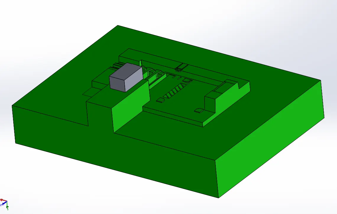
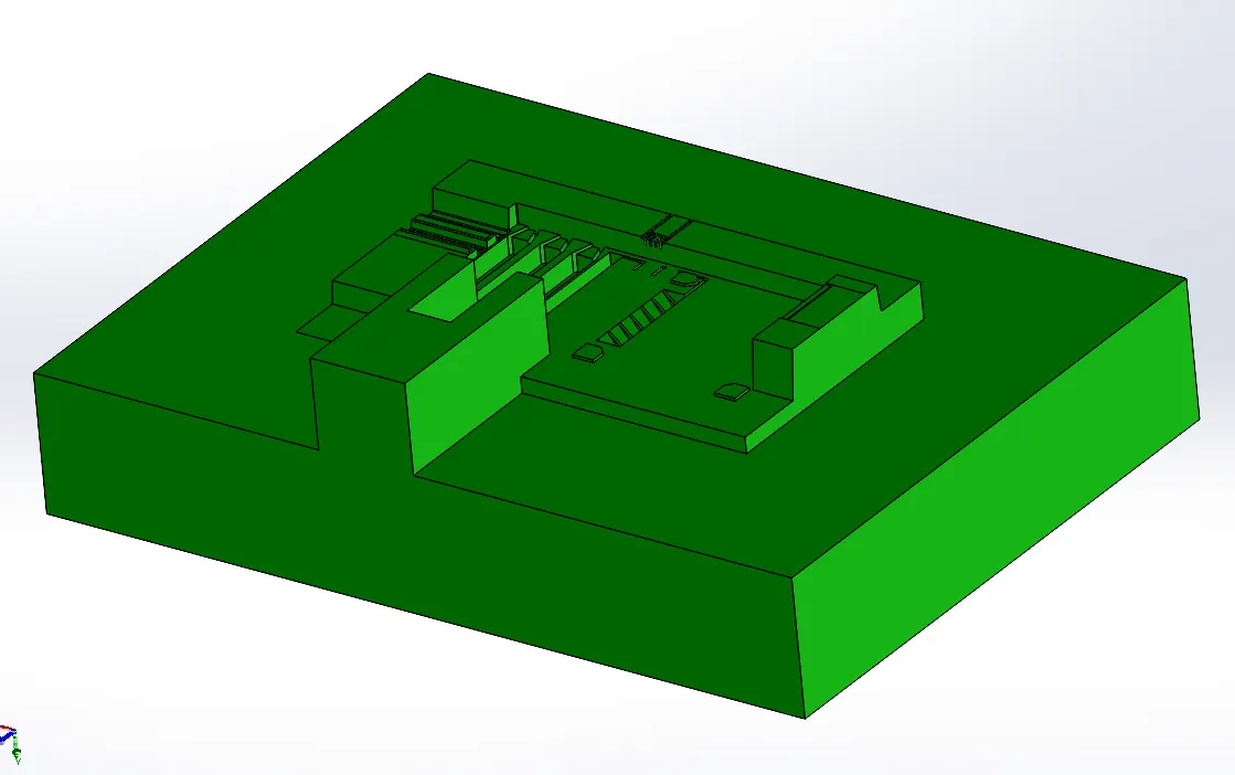
- Matching fillets as in slider body is provided.
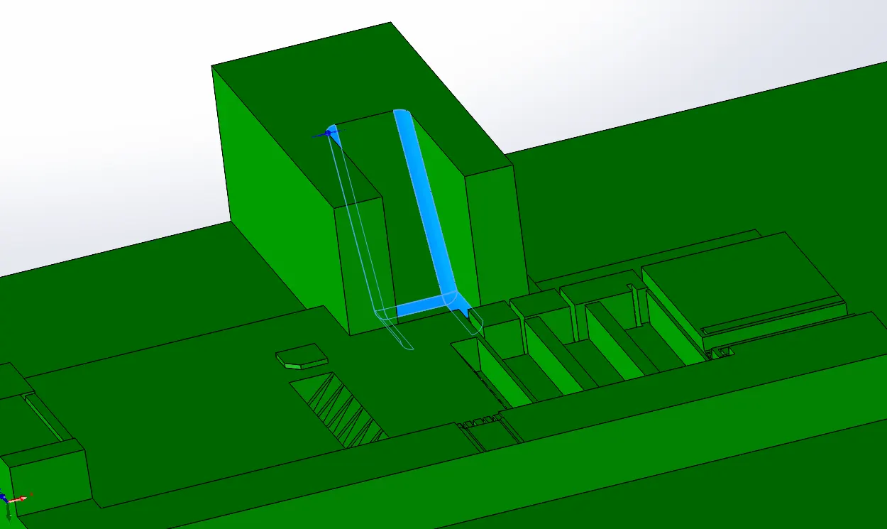
- Similarly for SLIDER02 in cavity sketch is done which accomodate every feature of and near undercut region. And sketch plane and sketch is then used to separate slider body with cavity using SPLIT command.
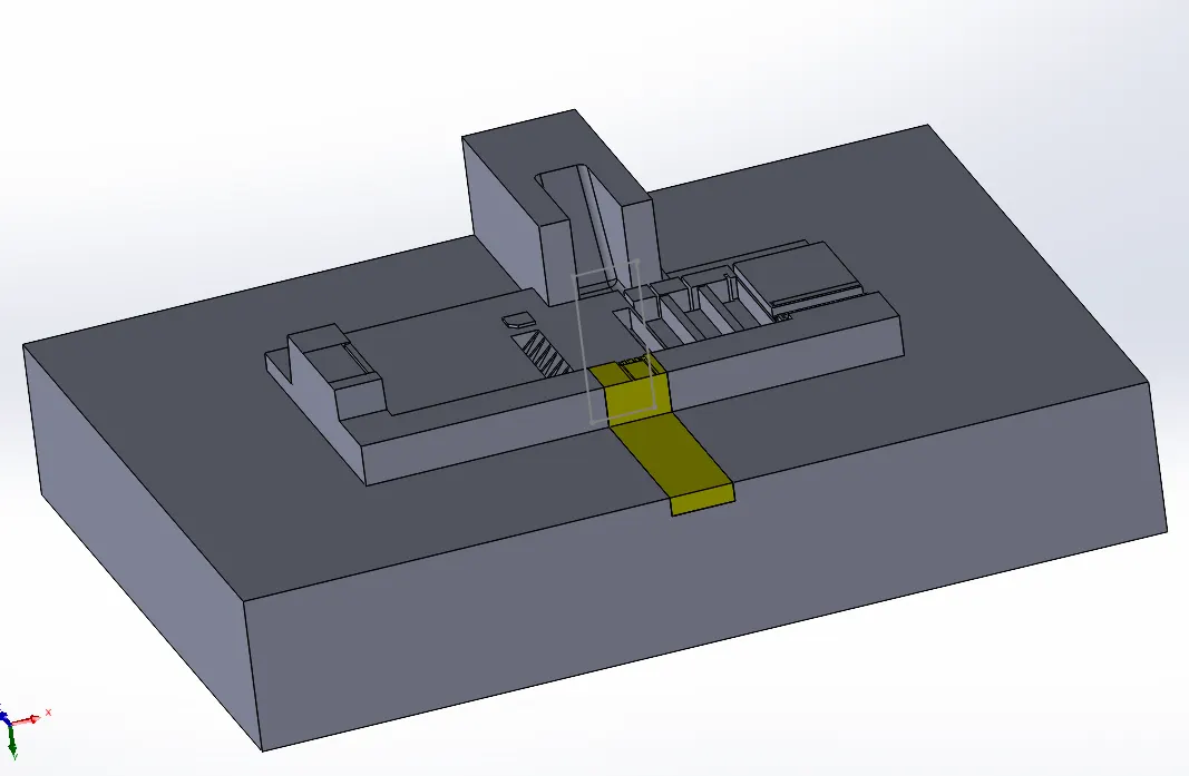
- Slider body is then modified as per requirement.
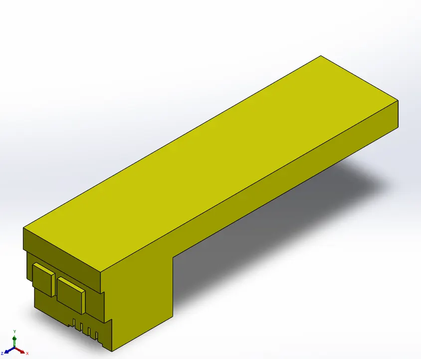
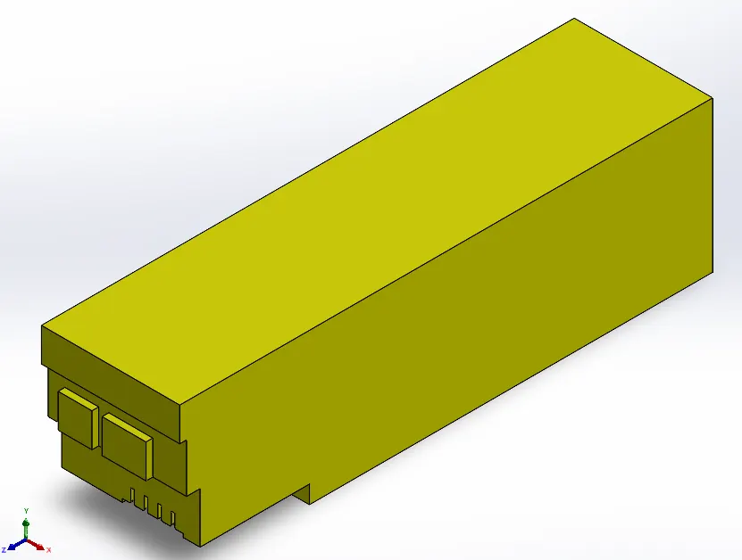
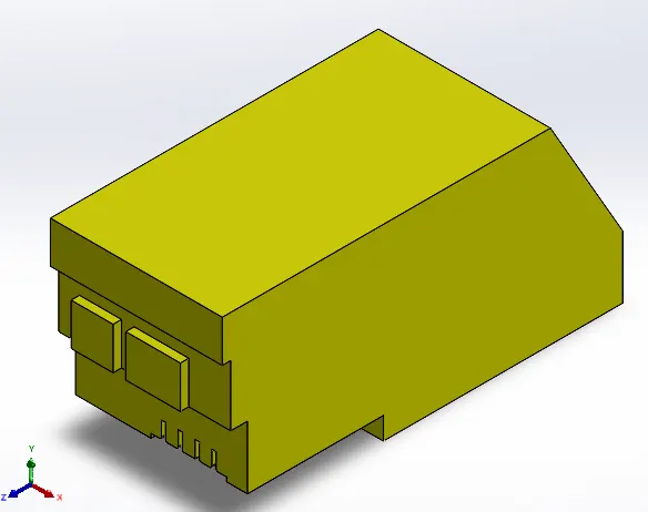
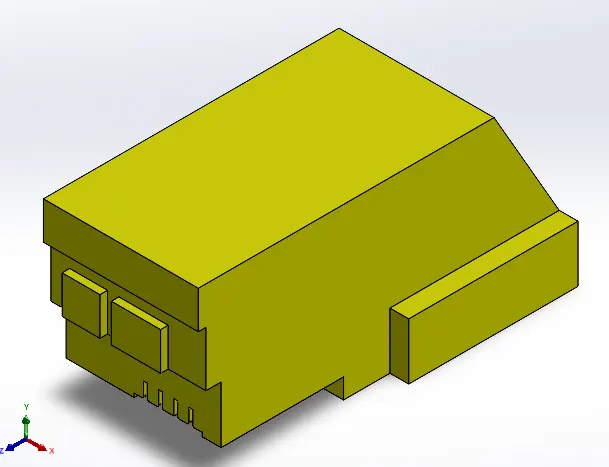
- Upto chamfered edge of slider material is extruded so that cavity similar to slider shape can be formed.
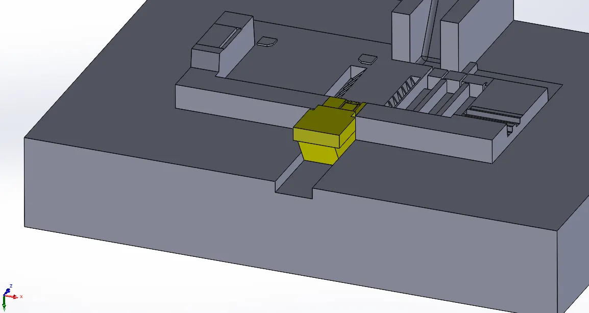
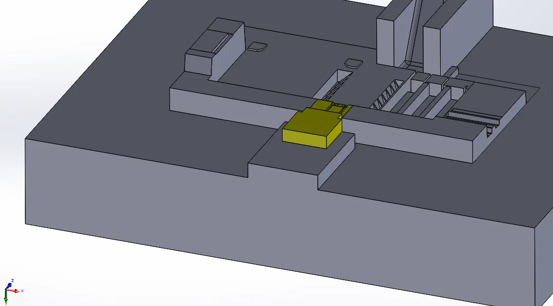
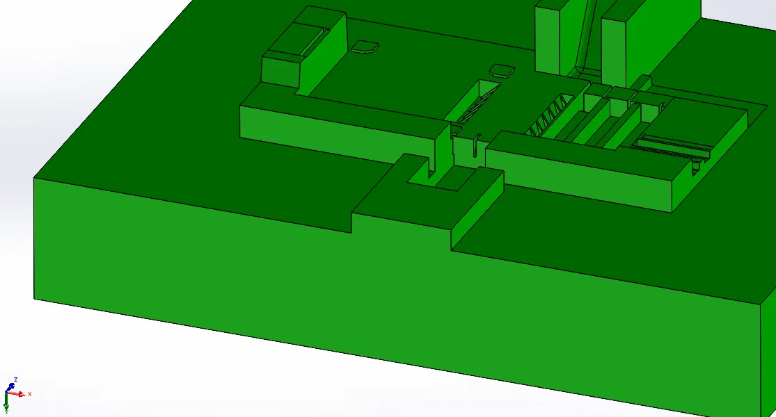
- Relief were provided by moving face highlighted by 2mm in cavity block.
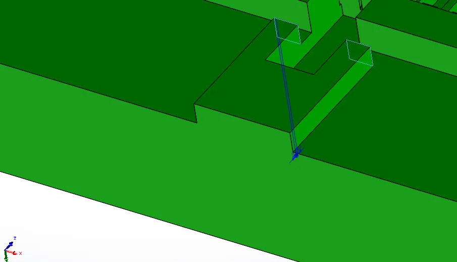
- Slots for limiting both sliders motion is provided onto both side of each slider in Core block.
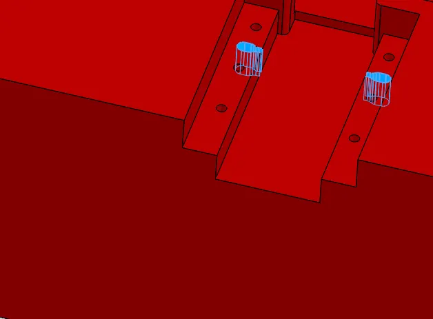
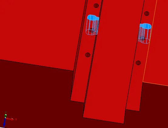
- Tap drill hole of M6 size and 20mm depth were provided on sliders rails so that bolts with washer of standard size can be placed in them. Bolts and washers are need for constraining the movement of sliders.
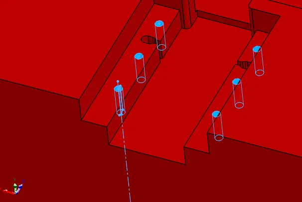
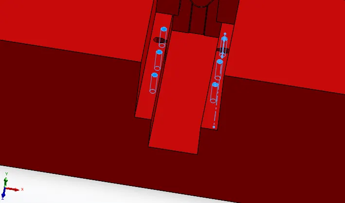
- For accomodating bolt heads and washers, matching depressions were made in the cavity but with clearance diametrically and in height.
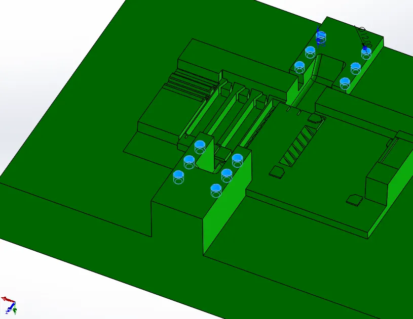
- Relief were provided on cavity side for avoid metal-to-metal contact.
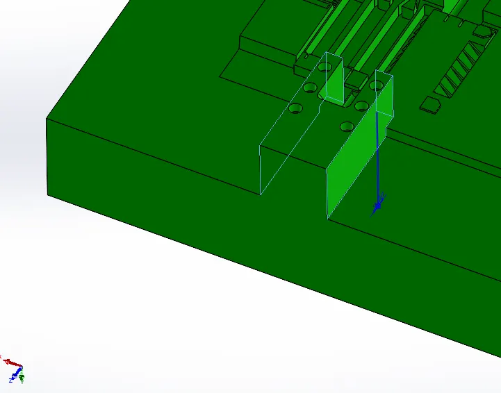
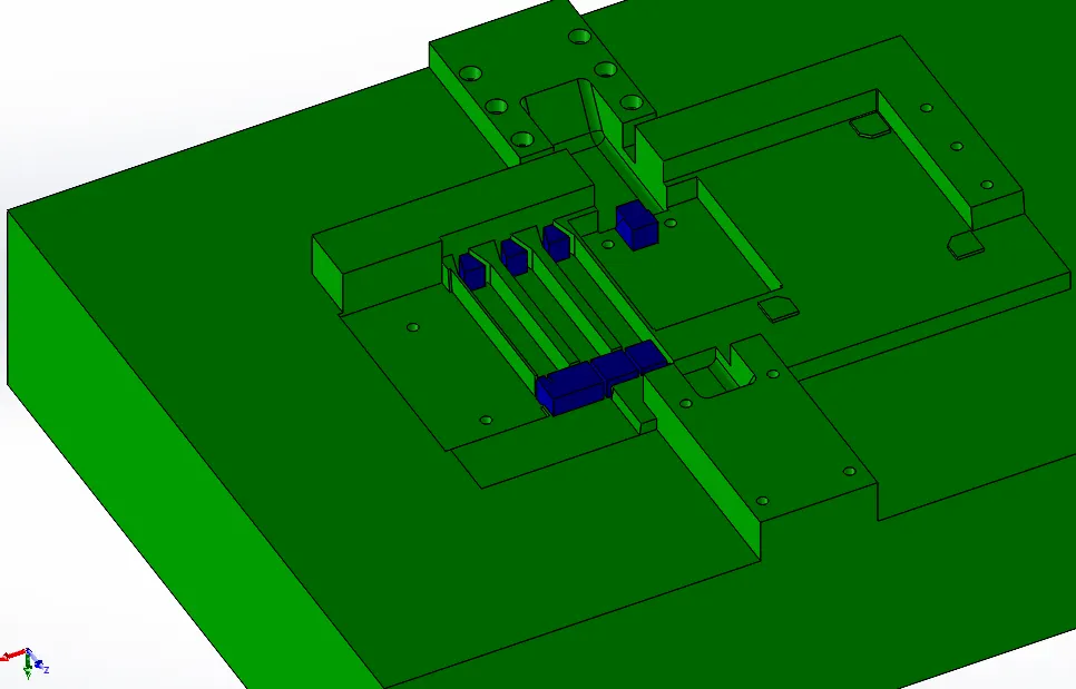
INSERTS : To avoid machining complexities, save time, material and cost these are machined separately and then fixed using bolts.
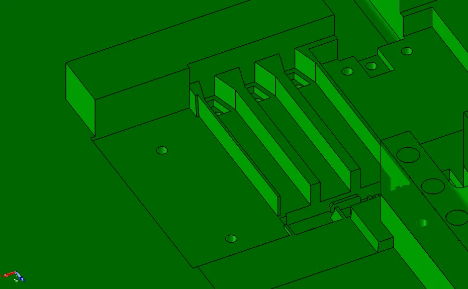
Cavity Inserts: In cavity block, multiple inserts of different shape and sizes were cutted. Aim is to avoid machining complexities so that highly precised component (CPU fan case) can be achieved.
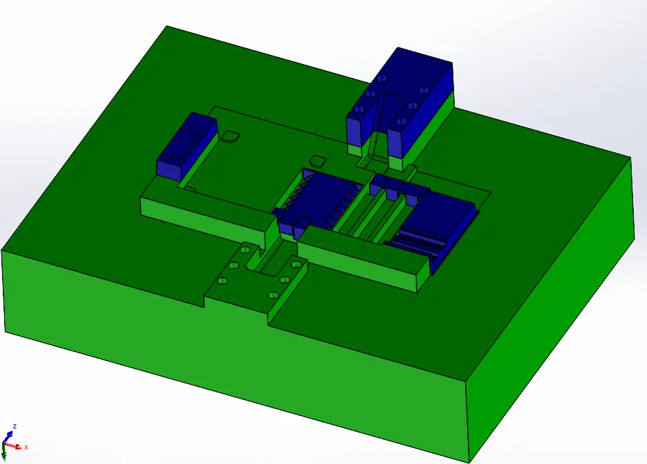
As compared to above the block below is relatively shallow, also the block height has been adjusted to 150mm for sake of standardization. Inserts are splitted is such a way that maximum features in the block lies in same plane.
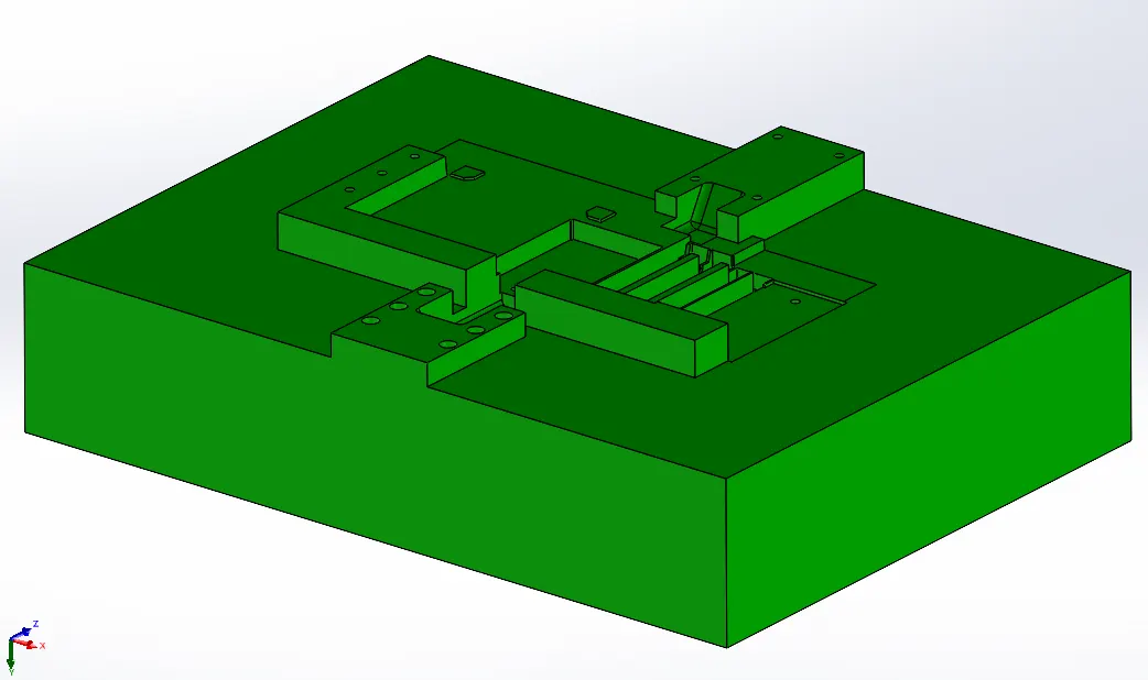
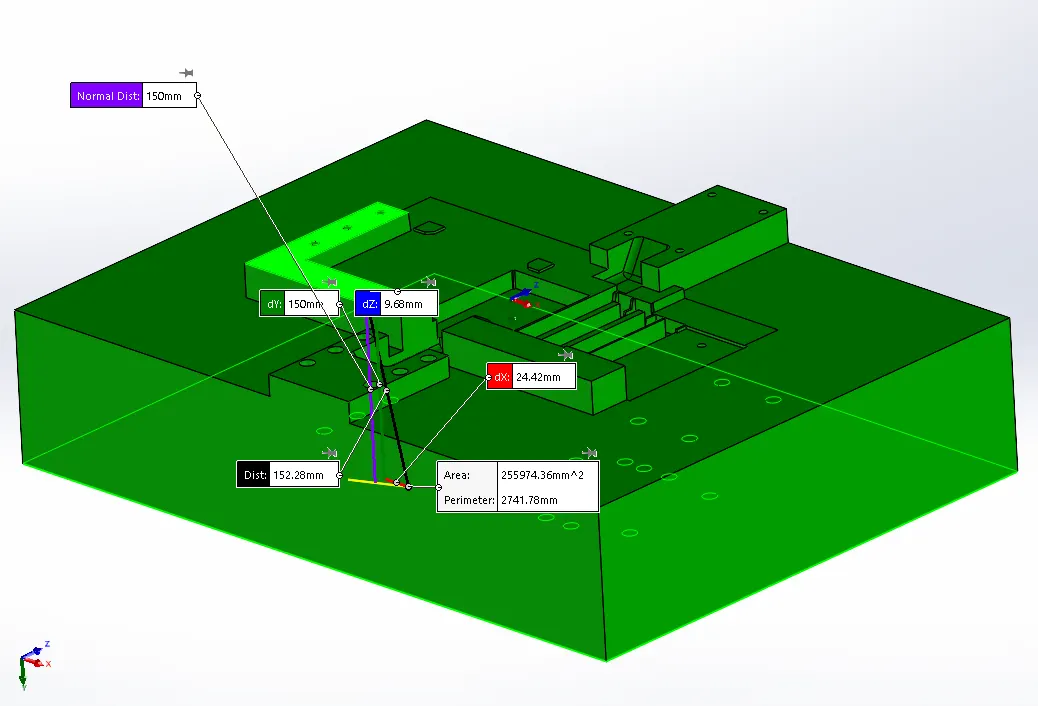
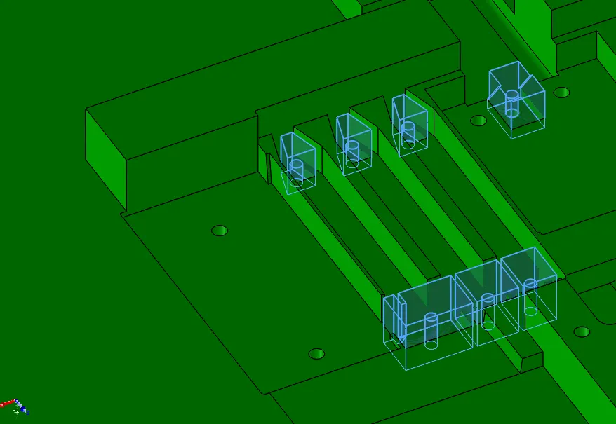
Counterbore holes for M6 bolts were provided on the cavity block to fix inserts.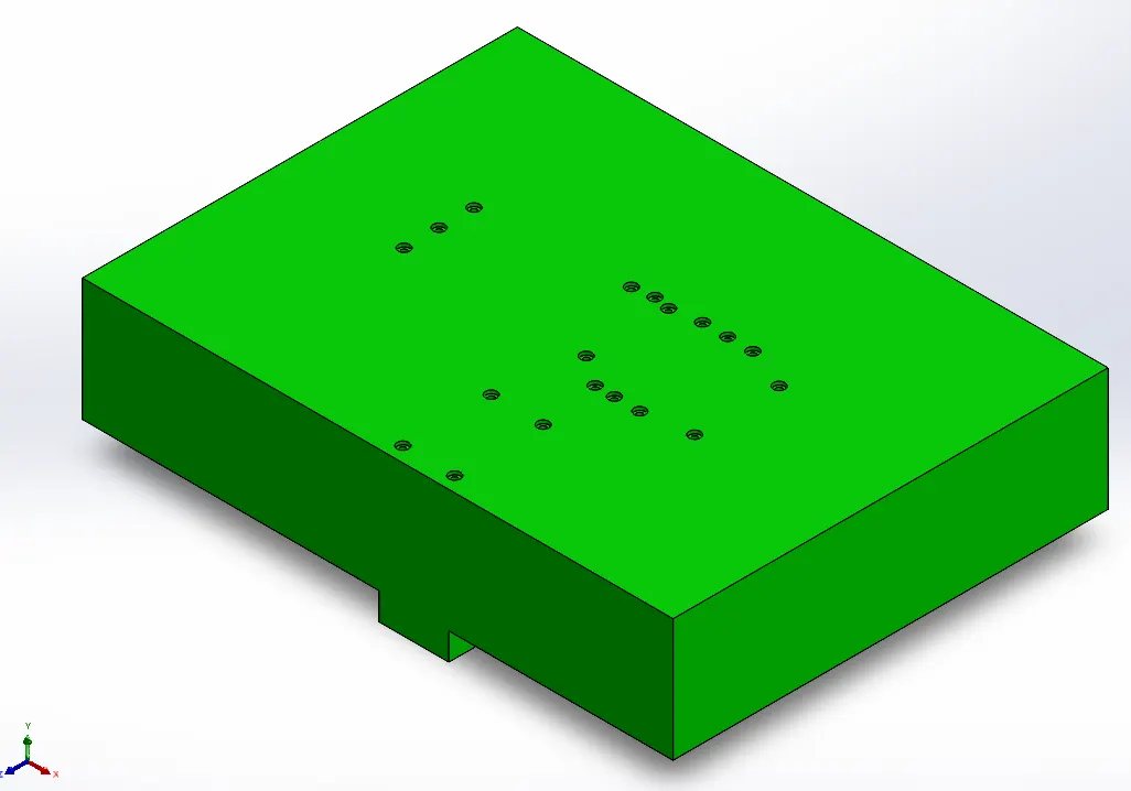
Depending upon their size and height available, 5mm dia holes are done on inserts for inserting M6 bolt.
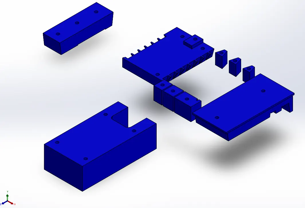
Inserts with single bolt fixing point are provided in some additional depression in the cavity block. This is done to avoid any orientation problem while assembling the cavity block with inserts.
Core Inserts:
In core block only two big inserts were provided.
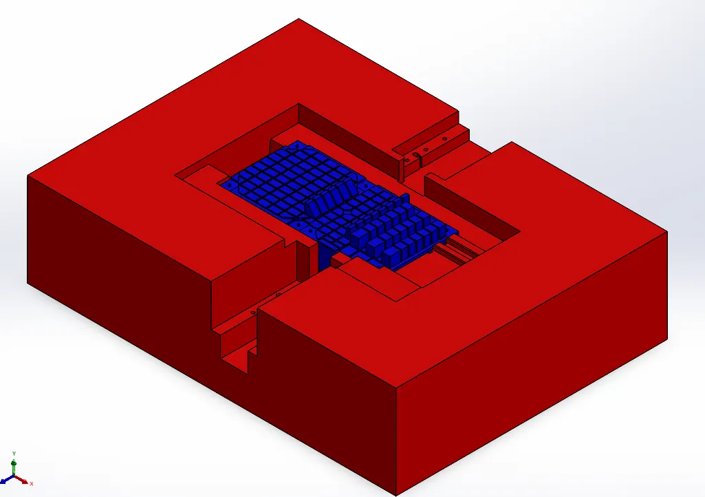
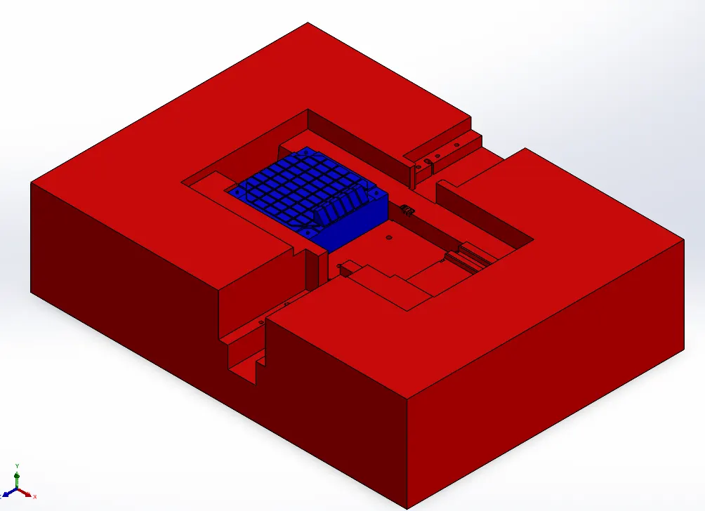
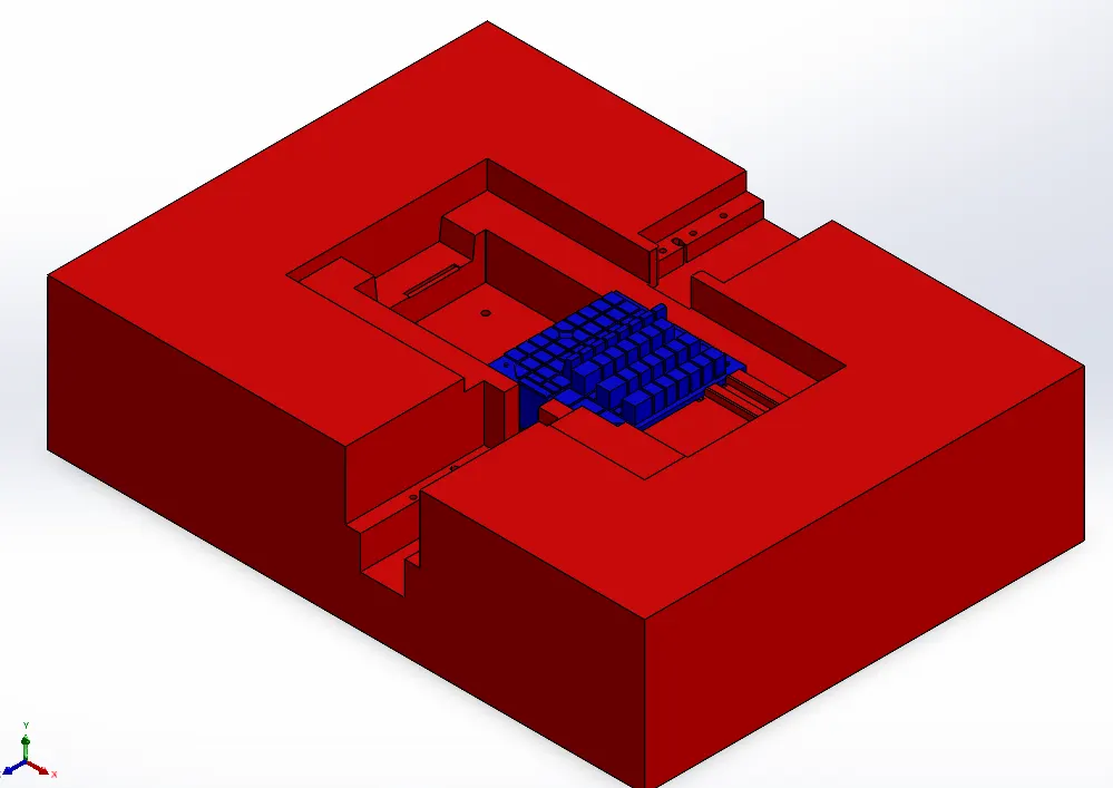
For fixing these inserts Counterbore through holes are provided in core block. And further 5mm dia holes are provided in inserts for accomodating M6 bolts onto it.