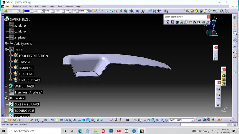
Week 9 - Challenge 2 - Switch Bezel Design
SWITCH BEZEL
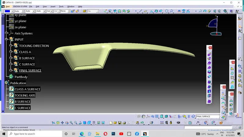
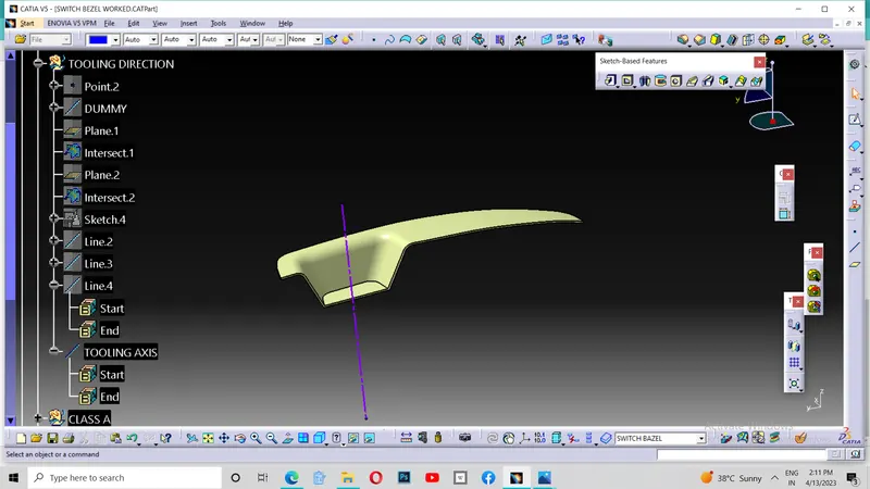
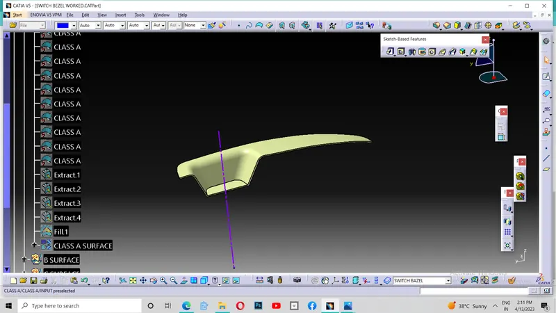
As per the given Switch Bezel CATPart file, I designed for my needed surface. In the given data, there was Class A surface of the Switch Bezel. By joining all of the surface part together after some repairing I got my needed Class A surface for the creation of the B and C surfaces.Then I made my joined class A surface as Publication. Then I made new geometrical set named tooling direction inorder to make my tooling axis.
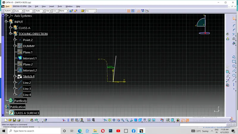
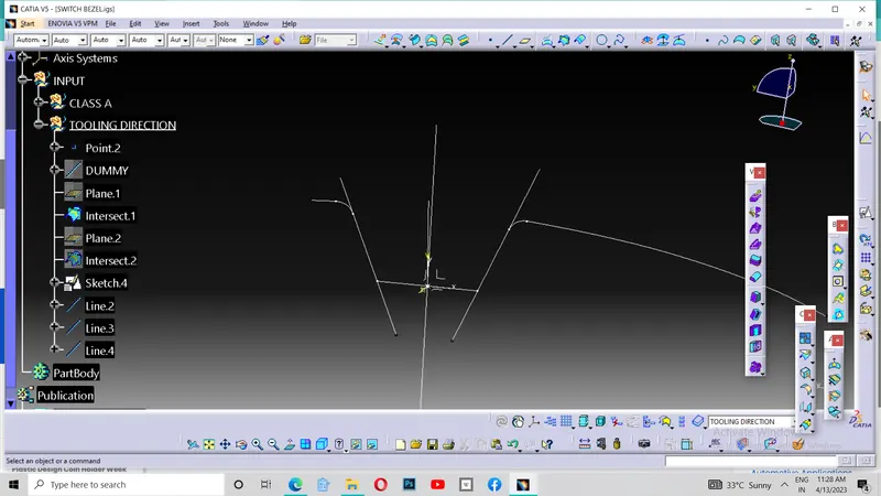
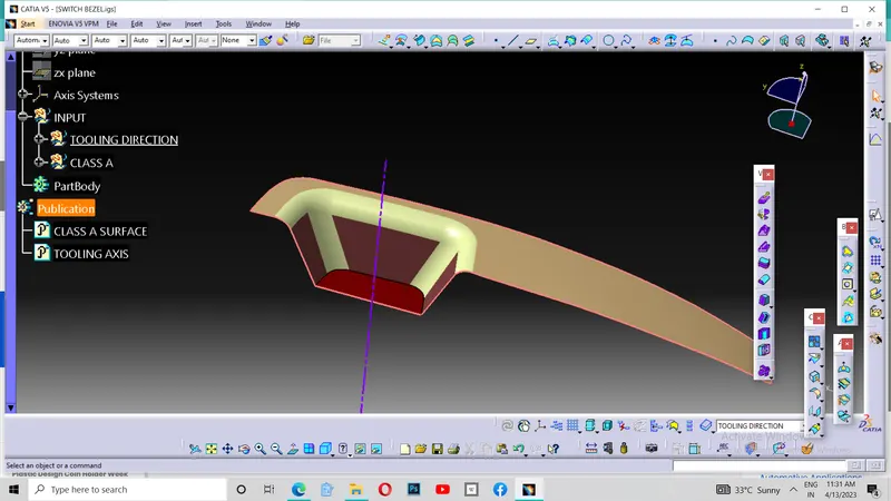
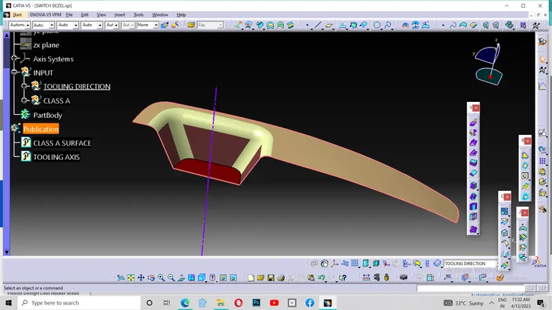
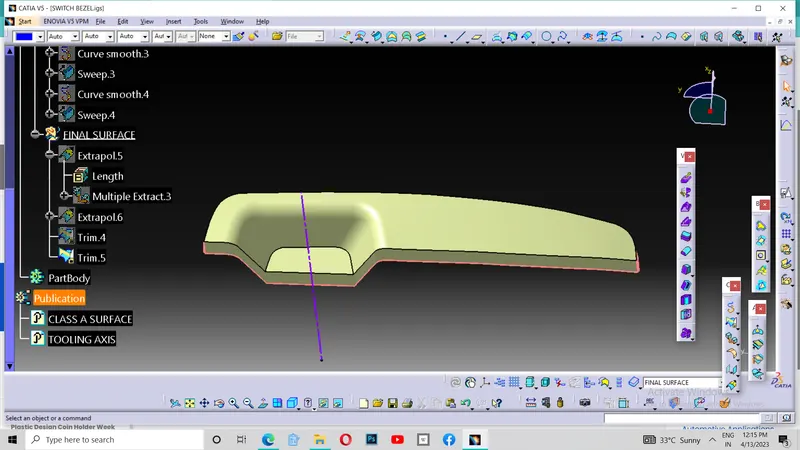
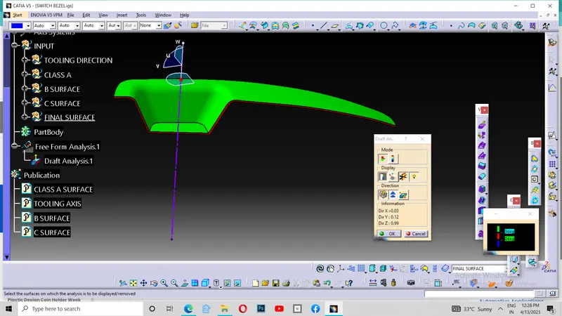
For the craetion of the tooling axis, Firstly I made a point in the middle of the base of the Switch Bezel. From that point, I just drawn a line in the Z direction as a Dummy tooling axis for the understanding of the Tooling axis direction roughly. Then I created a plane in that middle point by taking YZ plane as the reference direction. Then I drawn an intersection the body with the plane and got a curve. In that curve, I extent the inclined surfaces and drawn a bisect line from that middle point. Then I made an axis in that middle point inorder to draw a sketch in zx plane. Then I drawn intersection of the surface in that axis. There I got only 1 inclined side. I extented that line and drawn a line from the origin and make angle between them as 5.38 degrees( The minimum inclination is 3 degrees. After draft analysis , I adjusted the value). Then I exited from the sketch after making extented inclined line and intersection line as constructional elements. Then I drawn a bisect between the two lines and thus I got my required tooling axis. I coloured it , Thickened it and change the type of the line.
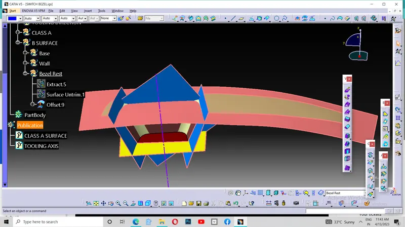
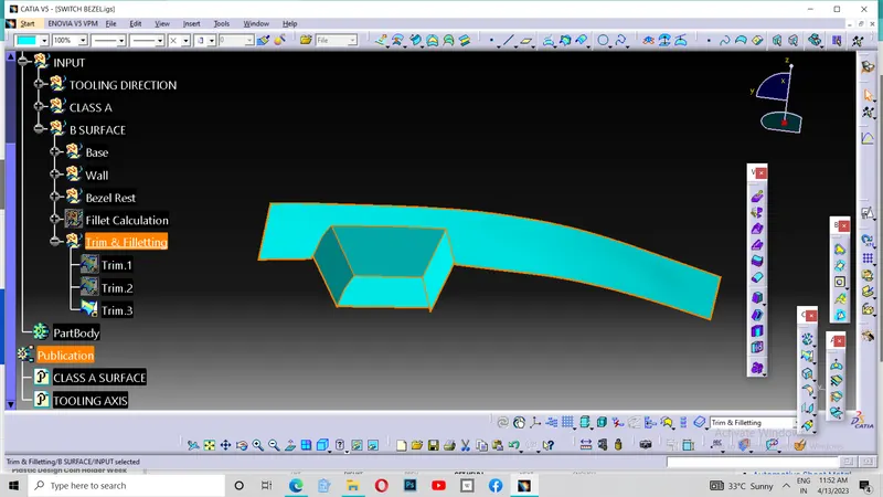
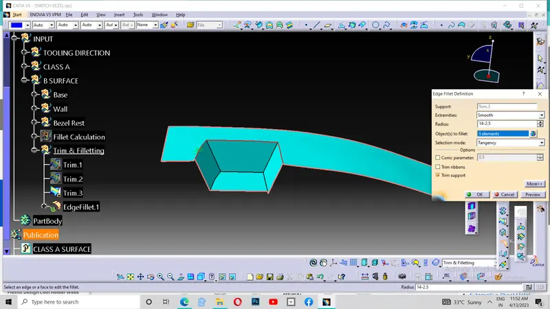
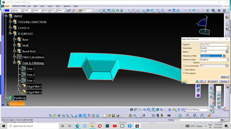
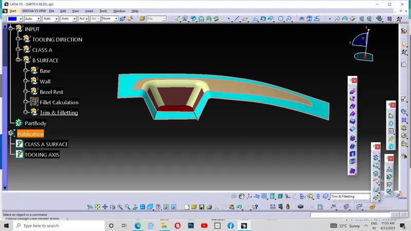
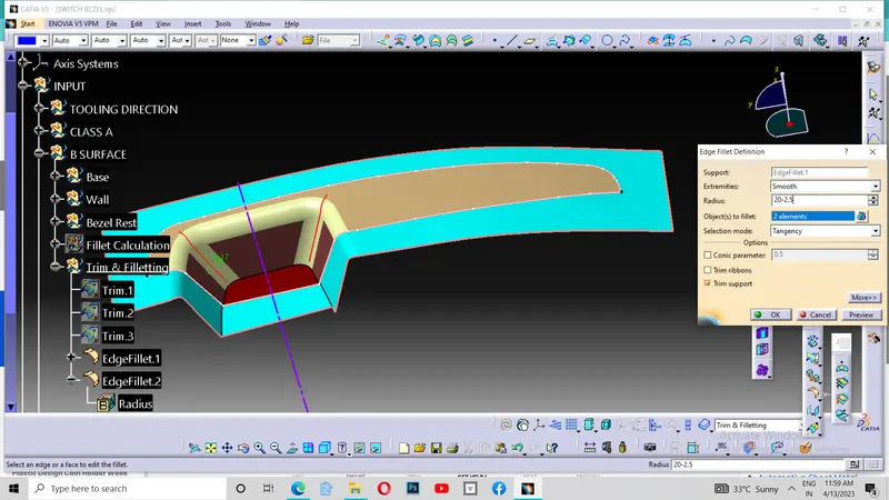
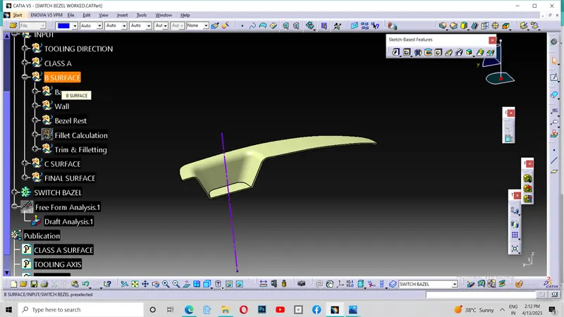
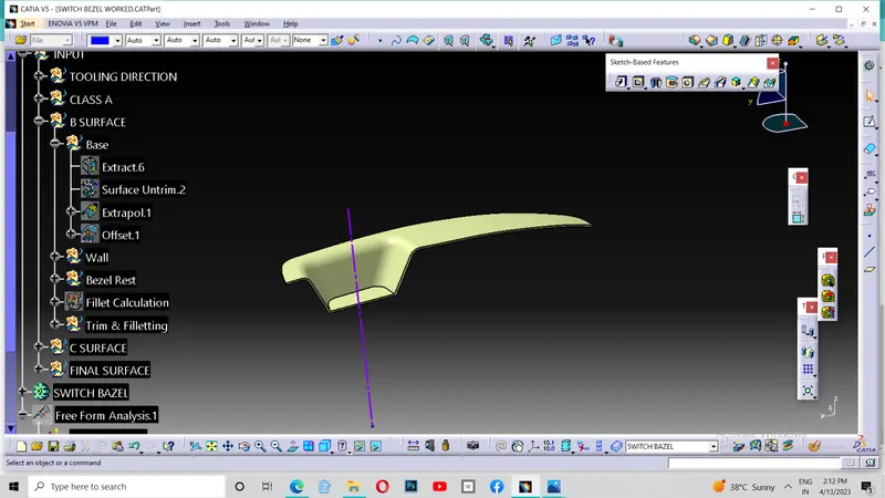
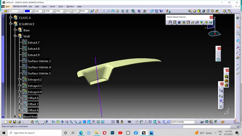
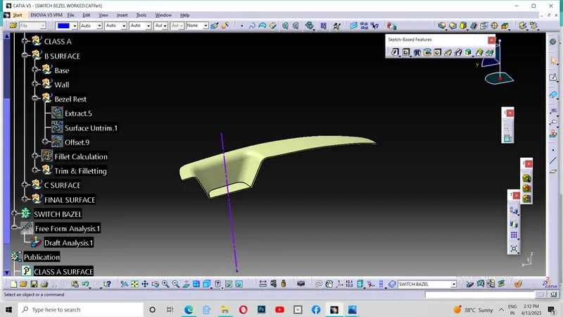
After getting the tooling axis, I started to work on the B surface. For that , I created a new goemetrical set named B surface. I extracted the Bezel rest surface , the walls and the base for avoiding the fillets and then untrimmed everything. After untrimming I extrapolated the needed surfaces in point continuity. Then I offsetted them to 2.5 mm and trimmed the required portion. Then I started to give fillets.
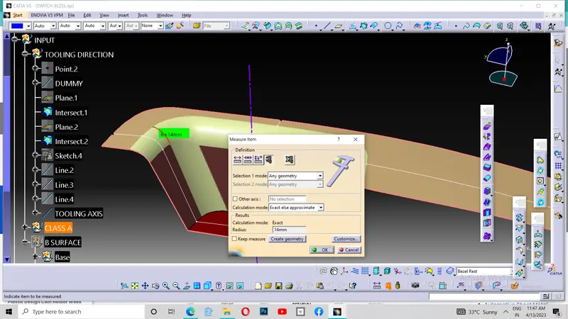
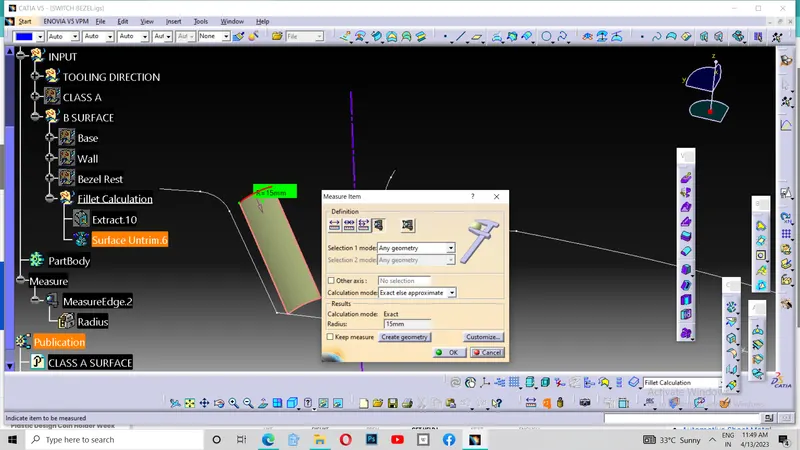
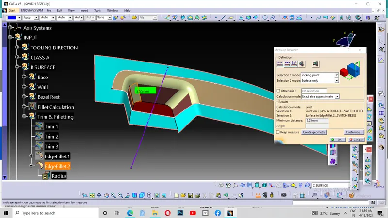
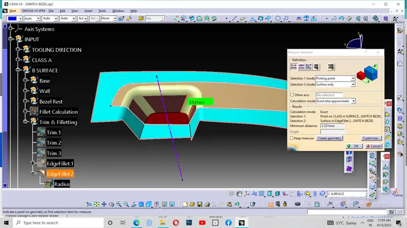
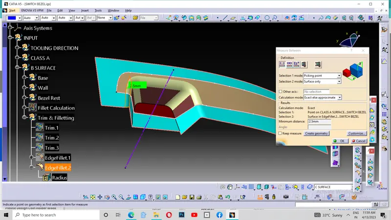
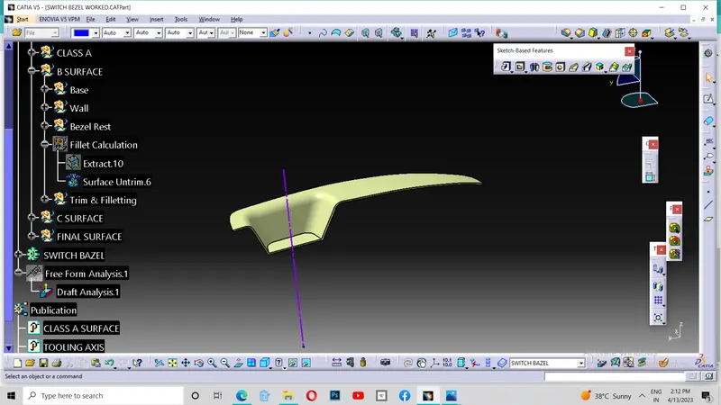
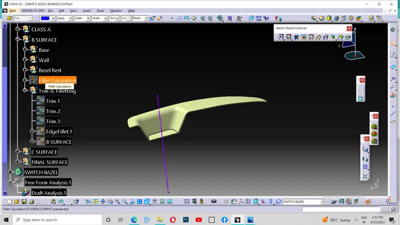
Inorder to give the fillets, I meassured the edges of the class A with meassuring tool . Then for the B surface , I given the fillet values by substracting it with the thickness of the part ( That is, 2.5 mm). And checked the distance between the B surface and Class A surface by picking points in needed sides and confirmed the fillet values. Thus I got my B Surface.
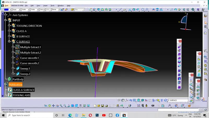
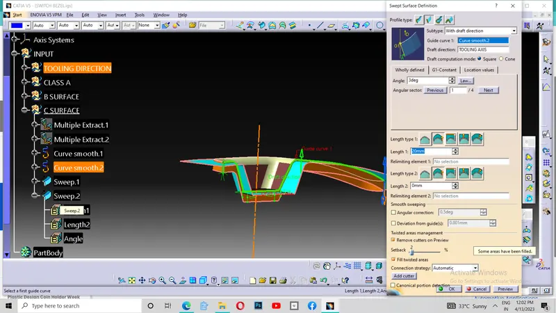
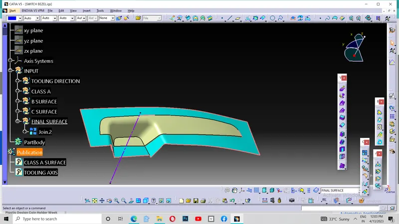
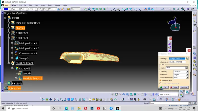
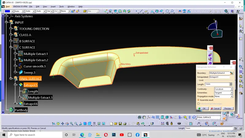
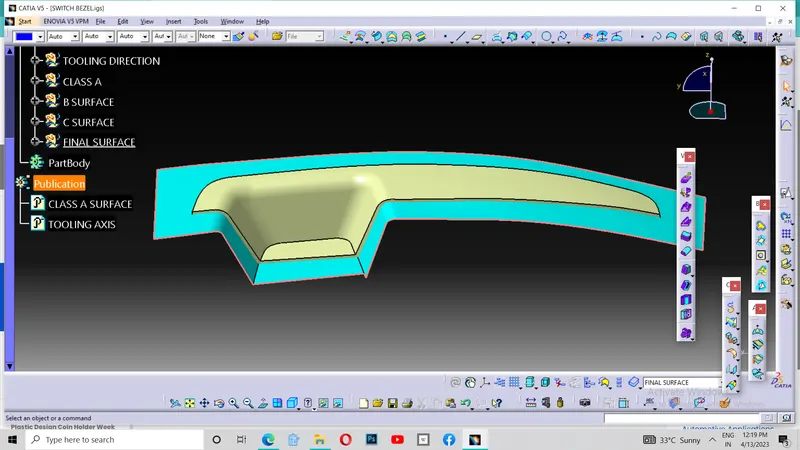
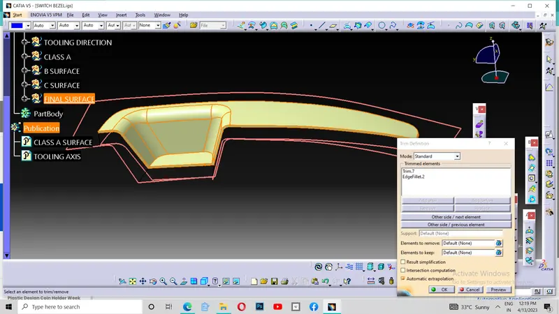
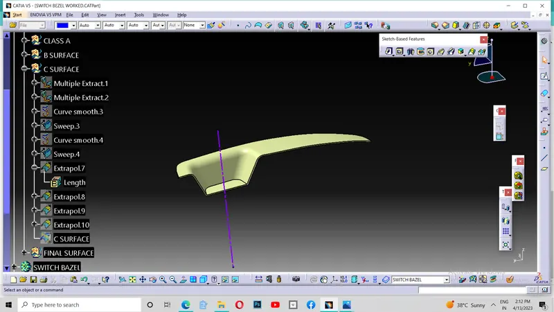
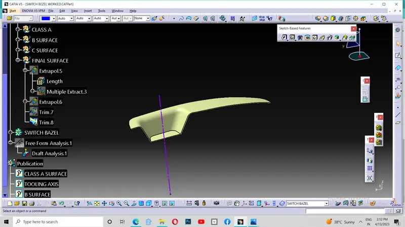
Then I made a new geometrical set named C surface for the creation of C surface. For that, I taken the boundary from the class A tangentially and smooth curved it in 0.003 mm deviation. and sweeped it. Then I found some discontinuity between Class A and C surface . Then I extrapolated the Class A and trimmed it with C surface . Then I joined them and trimmed it with the B surface and got my required A, B and C surfaces.
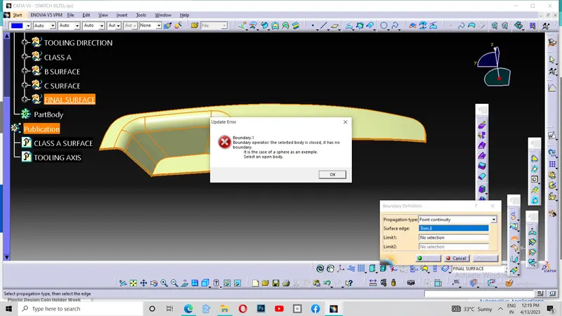
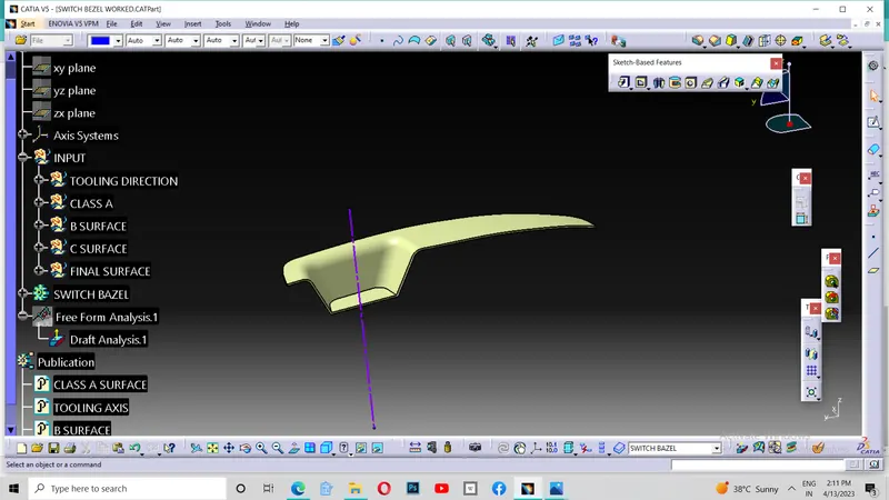
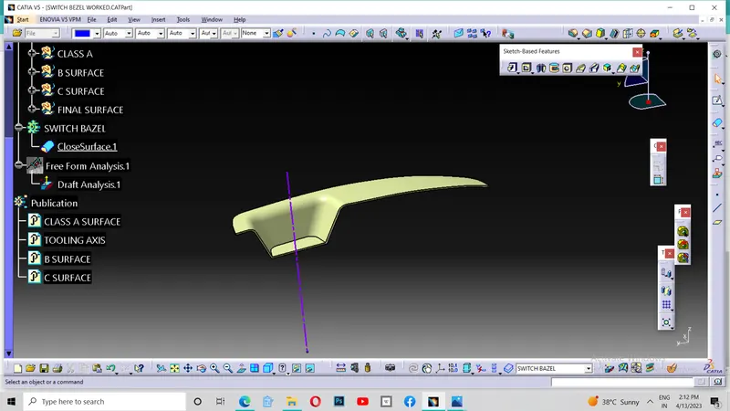
But the created Surfaces was hollow inside. So I have taken the design to the part design and using the close surface tool, I closed it . Thus I got my required part.
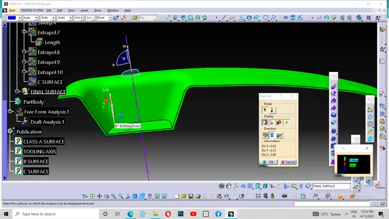
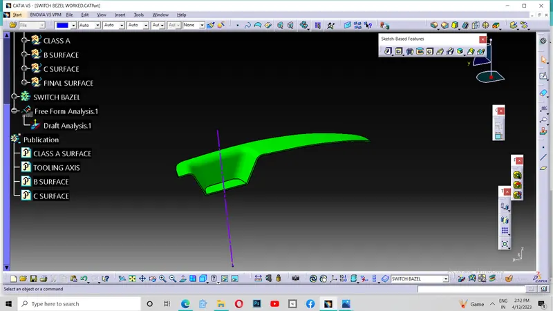
Then I checked it's draft analysis. Then the edges was at red. So I checked the angle and adjusted the tooling angle to 2.9 degrees and it get fine red colour. Thus I completed my challenge. Thankyou.