Week 9 - Challenge 2 - Switch Bezel Design
AIM: To create the switch bezel plastic component for the given Class A surface.
OBJECTIVE:
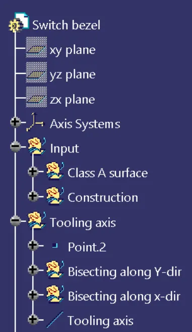
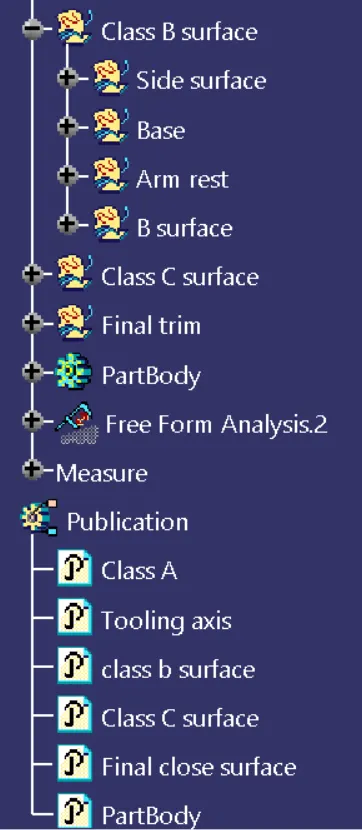
- Ensure proper tree structure
- All sketches should be created under the geometrical sets
- All geometrical sets should have a proper name based on the sketches present inside of it.
- Use close surface feature to make a solid body from the surface
- Use publication feature to publish Tooling axis, Class A,B and C surface
- Create proper tooling axis with respect to the injection molding
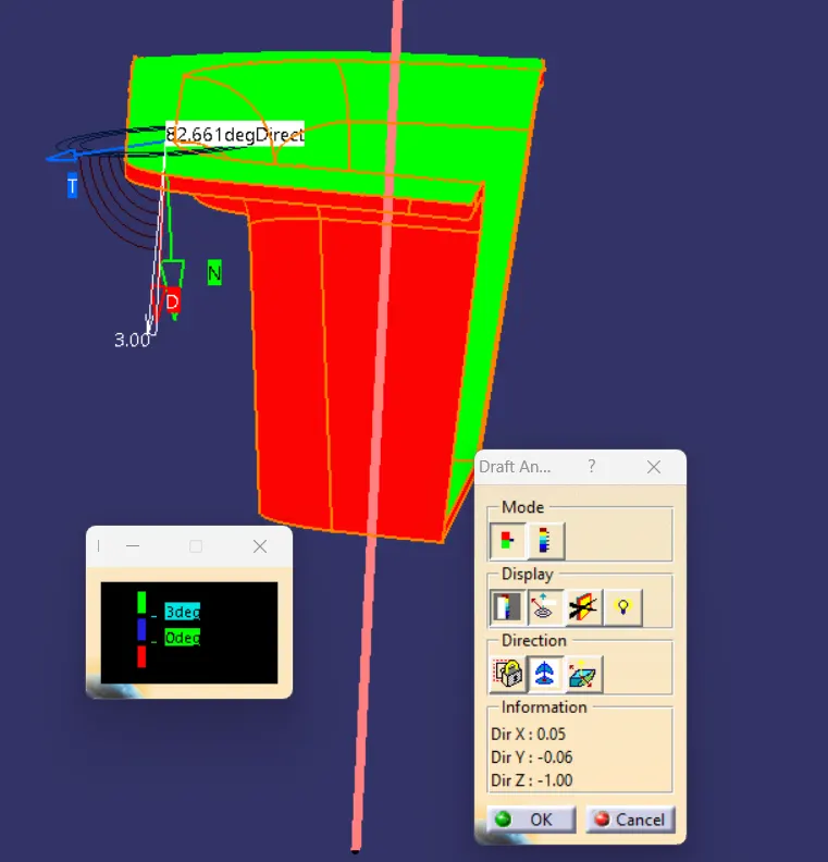
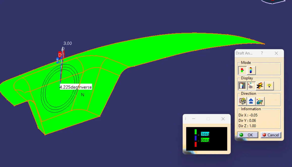
- Draft angle should be checked for proper ejection of the component from the mold after solidifying
PROCEDURE:
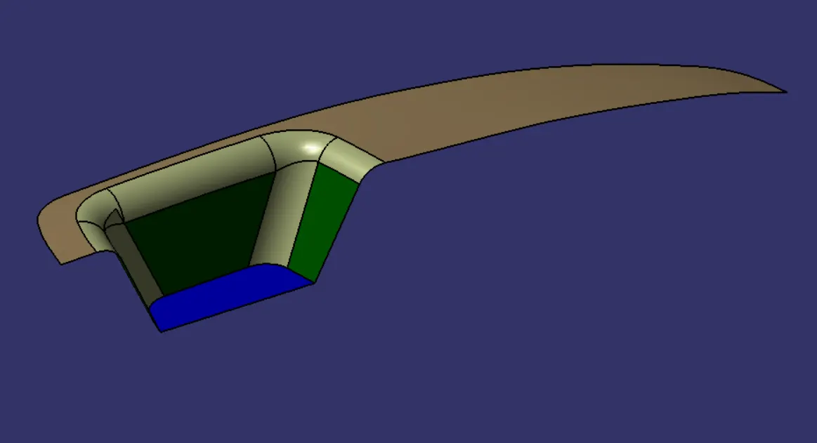
- Class A surface input
- Tooling axis creation
- Draft analysis for Class A surface
- Create Class B and C surface
- Join all surfaces to form enclosure
- Make solidify by using Closesurface command
EXPLANATION:
TREE STUCTURE:
CLASS A SURFACE:
TEMPORARY AXIS IN Y-DIRECTION:
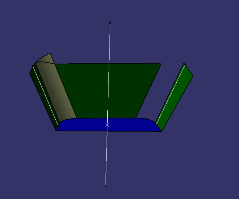
TEMPORARY AXIS IN X-DIRECTION:
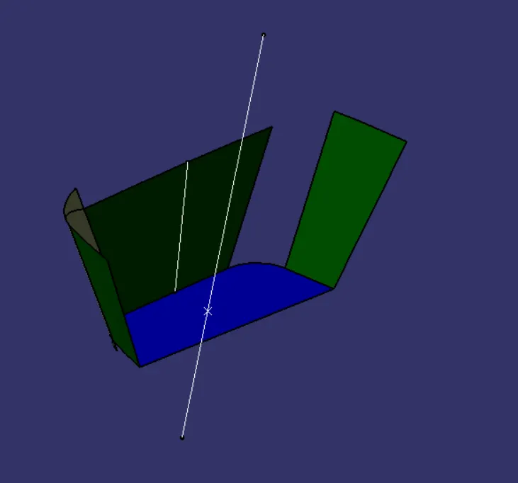
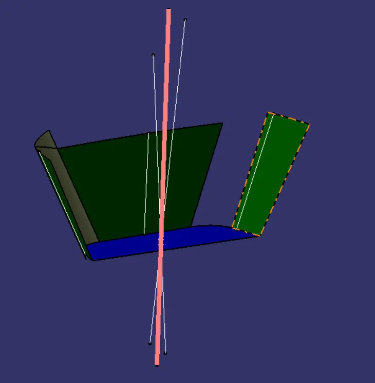
TOOLING AXIS:
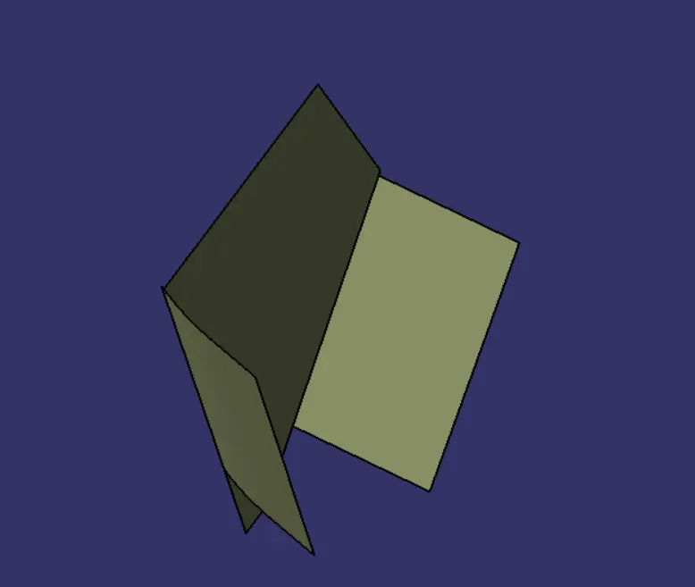
CLASS B SURFACE CREATION PROCEDURE:
1.SIDE SURFACE:
2. SIDE SURFACE WITH BASE:
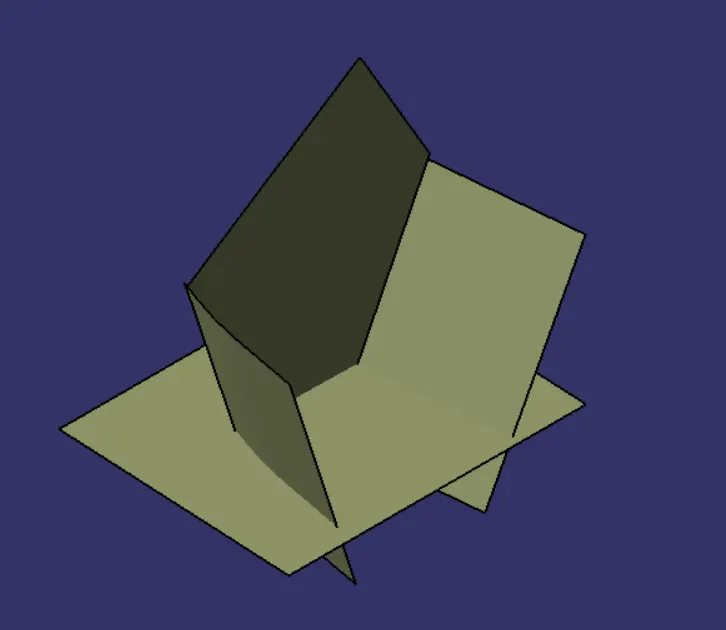
3.SIDE SURFACE, BASE AND ARM REST:
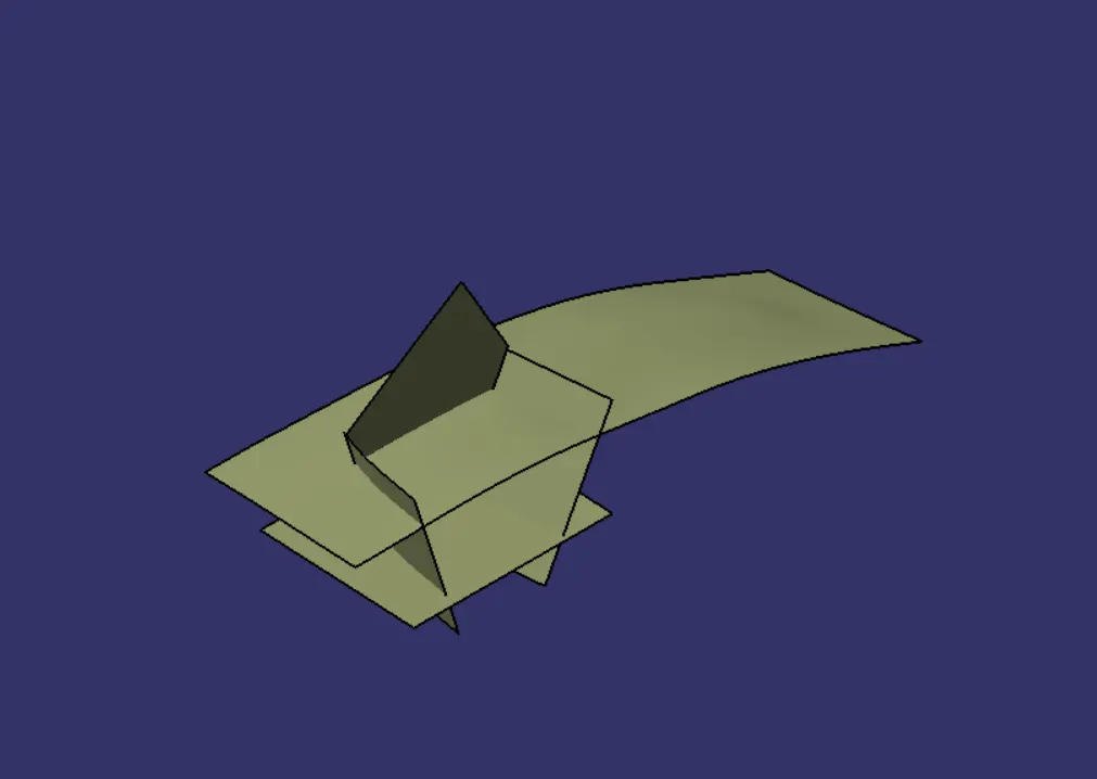
4.CLASS B SURFACE:
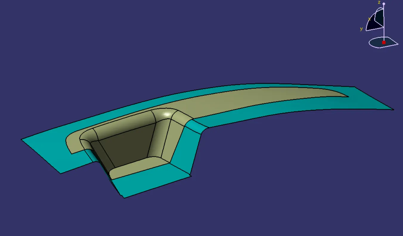
CLASS C SURFACE:
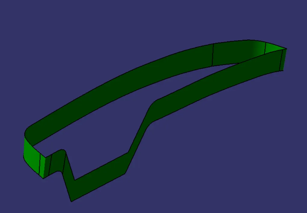
BEFORE FINAL TRIM:
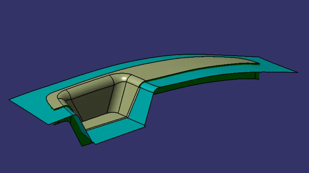
FINAL ENCLOSED SURFACE:
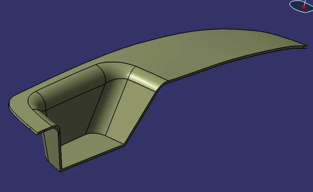
SOLID PART BODY:
DRAFT ANALYSIS:
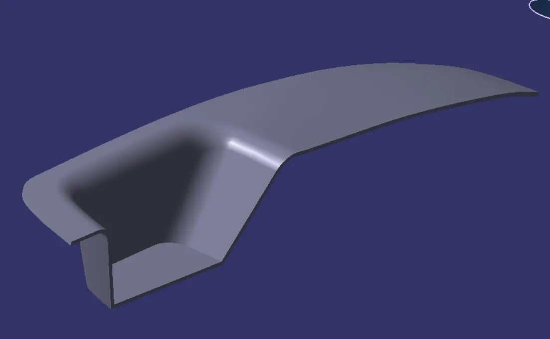
CLASS A SURFACE:
SOLID COMPONENT:
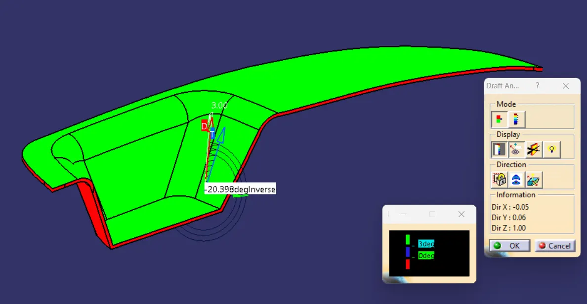
FRONT VIEW:
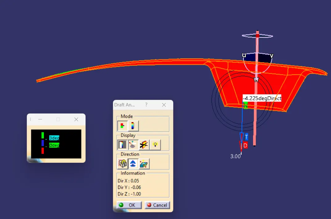
TOP VIEW:
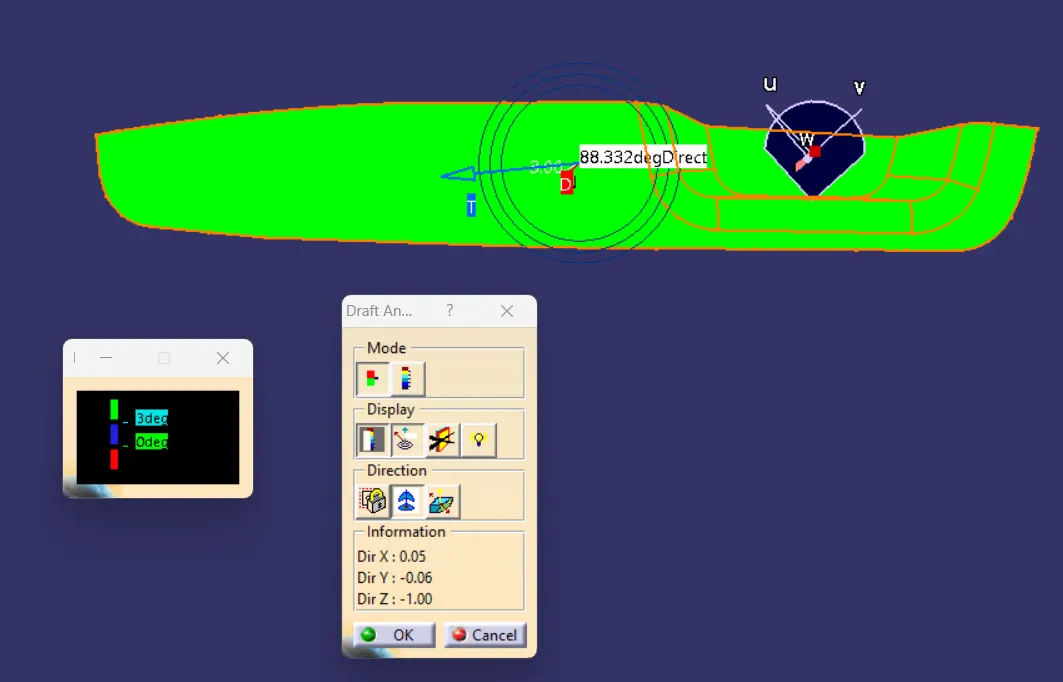
SIDE VIEW: