Week 9 - Challenge 2 - Switch Bezel Design
AIM:
To create the Plastic component design SWITCH BEZEL as per the engineering design standards.
Draft Analysis:
When a plastic component is made, we can observe that there is a draft angle given on each side from the base which is lesser than 90 degrees. This is because in the criteria of making a plastic material the mold should release the material when finished. if the mold surfaces are 90 degrees the material won't release from the mold because of friction due to contraction of material when cooled.
To resolve this problem we CAD engineers maintain a standard rule to design the plastic mold or die's in such a way that there will be no problem while ejecting the plastic component. So a minimum of 3 - 10 degrees of draft angle is given to every plastic component while designing.
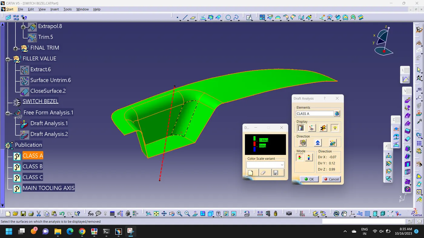
Draft analysis is performed on the given Class-A surface, and it is clearly observable that there is no negative draft on the surface.
Tooling Direction:
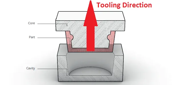
The Tooling direction is basically the direction that the molds pull apart. The mold is built in two separate pieces basically you have the cavity side and the Core side, The Core Pulls apart from the Cavity and that is called as the Dyeline or the Tooling direction
Overview:
The direction is main consideration of a part and mold parts because it defines movement of mold part and posibility of plastic part to come out from mold part (Core and Cavity)
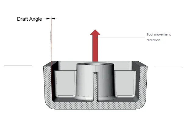
- In molding machine as you can see that the arrangement is given to open a mold along a direction is known as Tooling direction.
- In other words. The mold is built from two separate halves (core and cavity) and Tooling direction basically defines the direction of the mold which is gonna be pulls apart from the mold.
- Tooling direction is known as Primary direction.
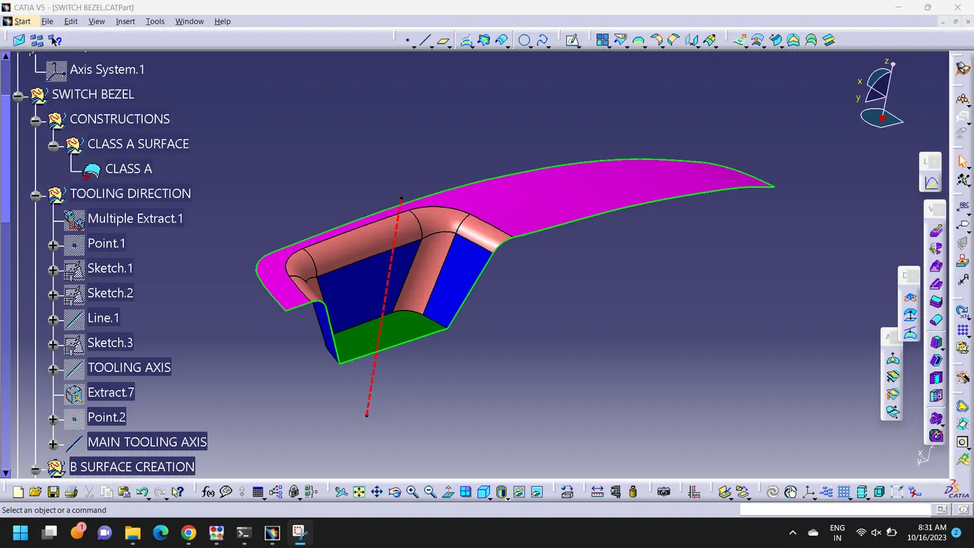
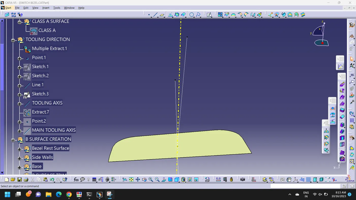
The tooling axis is created for the given class-A surface.
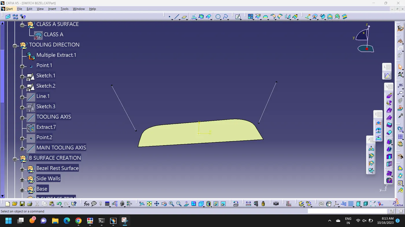
Creation of tooling Axis (Bisecting method)
1. Extract the base surface of the given Class- A Surface and create the center point of the Extracted surface
Class B Surface Creation:
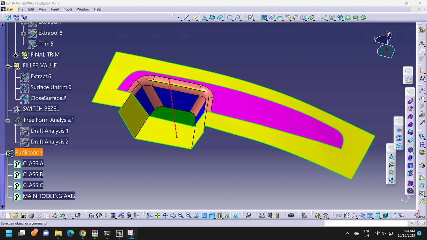
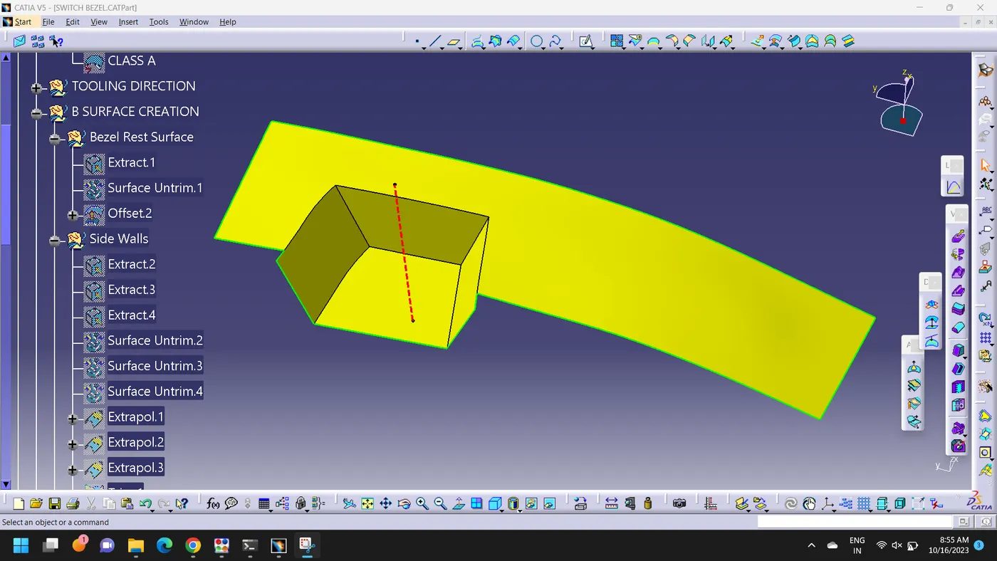
Class B Surface is created by extracting the each walls and untrimming and by extrapolating the walls of to obtain the shape by trimming the excess surfaces and offseting it to a certain distance based on the thickness of the model. The offseted surface will be the B surface
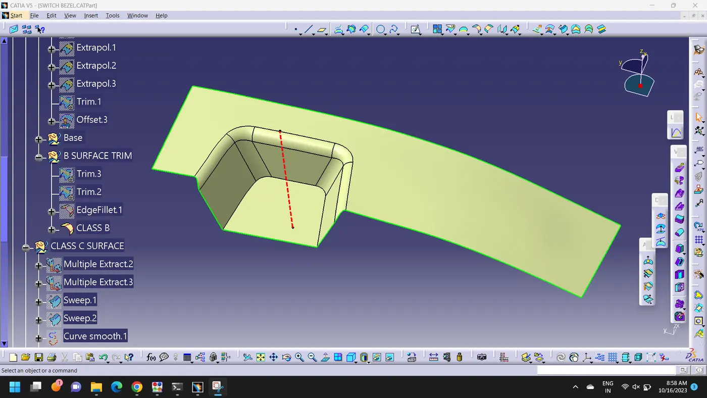
Class C Surface Creation:
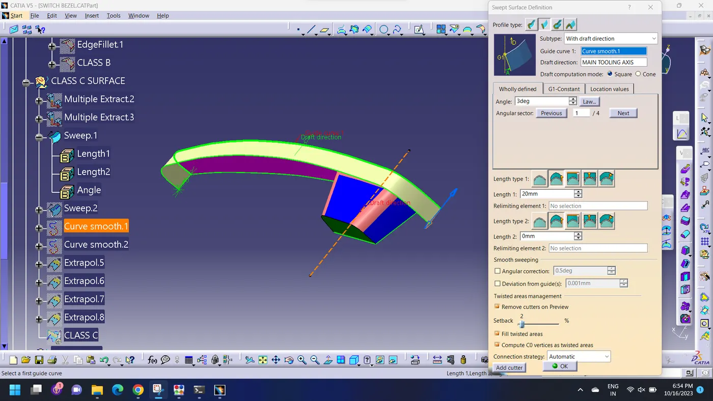
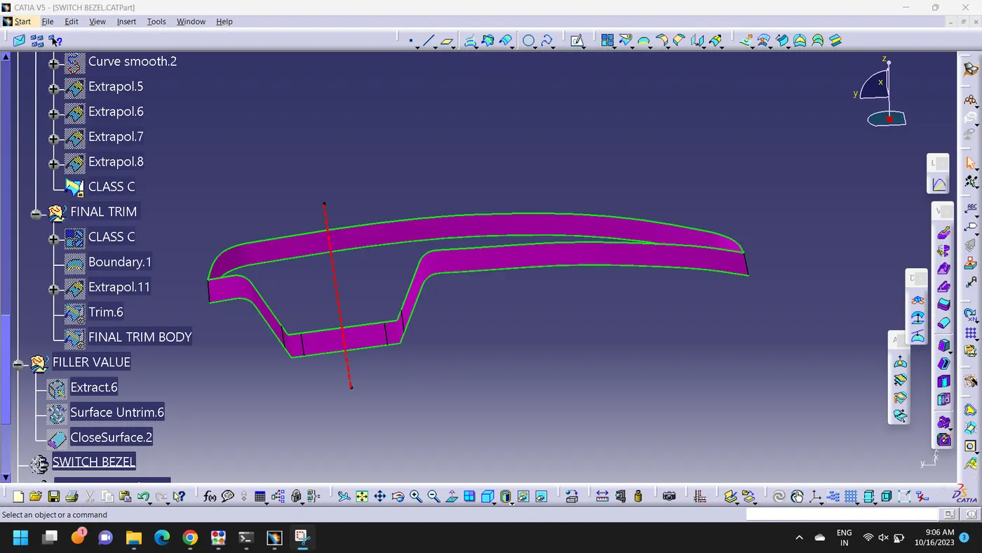
The surface created using a sweep command by sweeping the boundries of A Surface along the tooling axis to connect from A to B surface is known as C Surface.
The Draft Analysis is performed on the final component
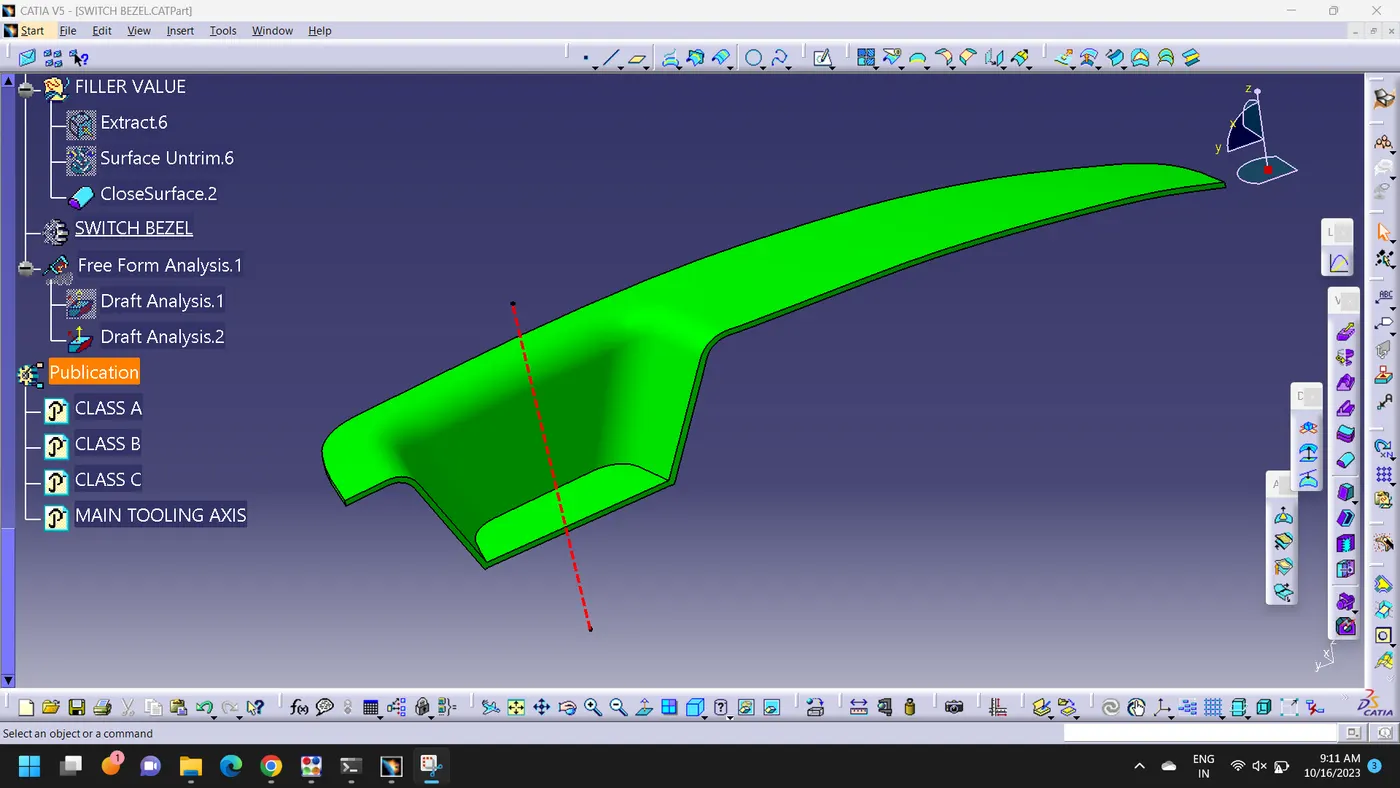
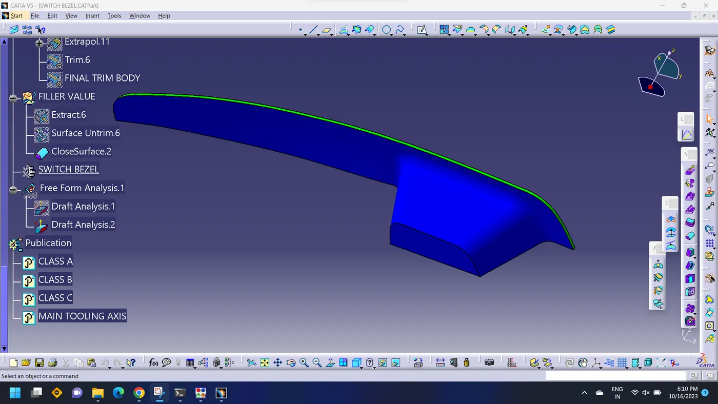
A 2.9 Degree of Draft angle is given to the final component and It can be seen that the there is no negative draft occurs on the A and C Surface hence the component is compatible with design and can be manufacture
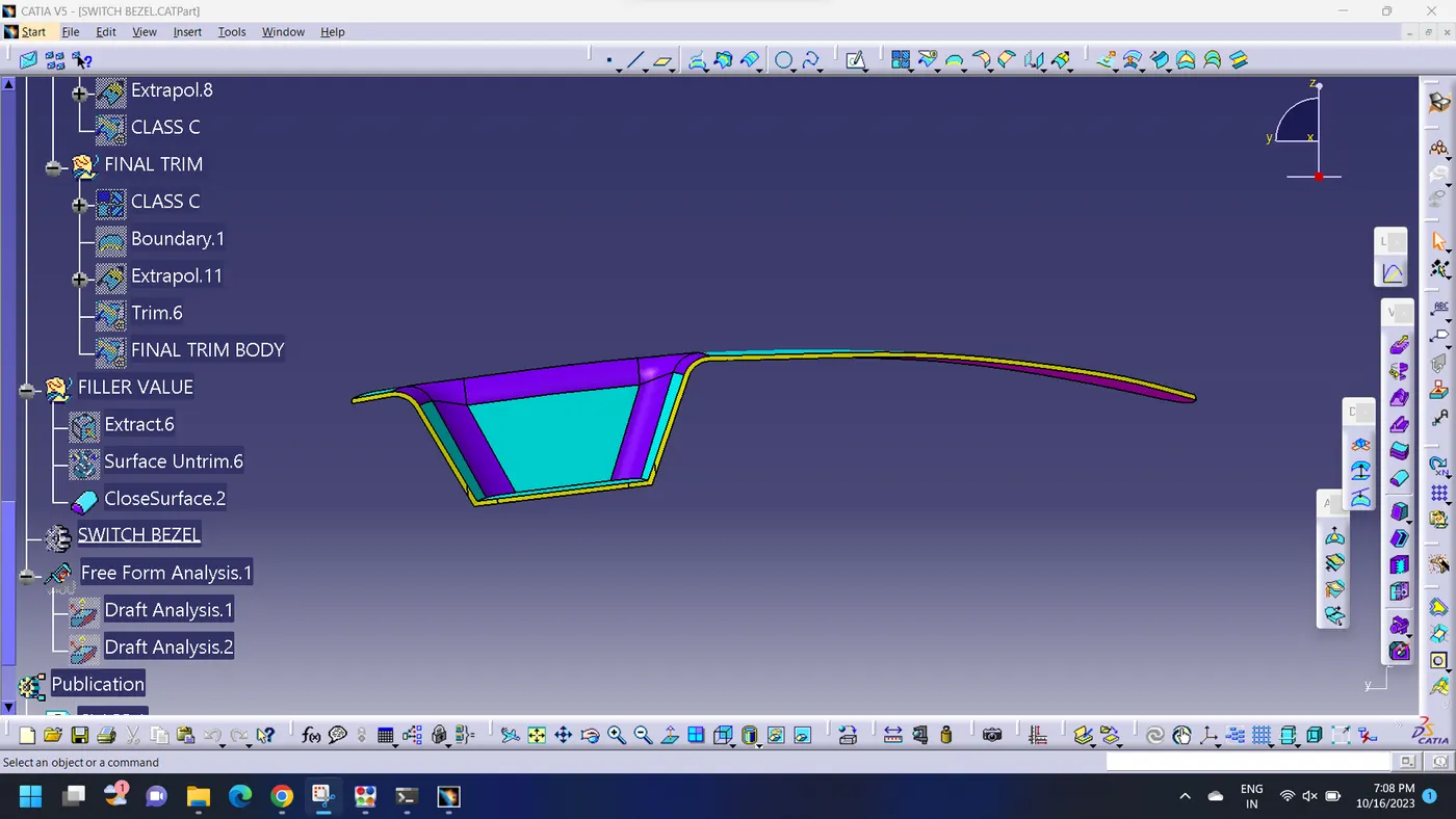
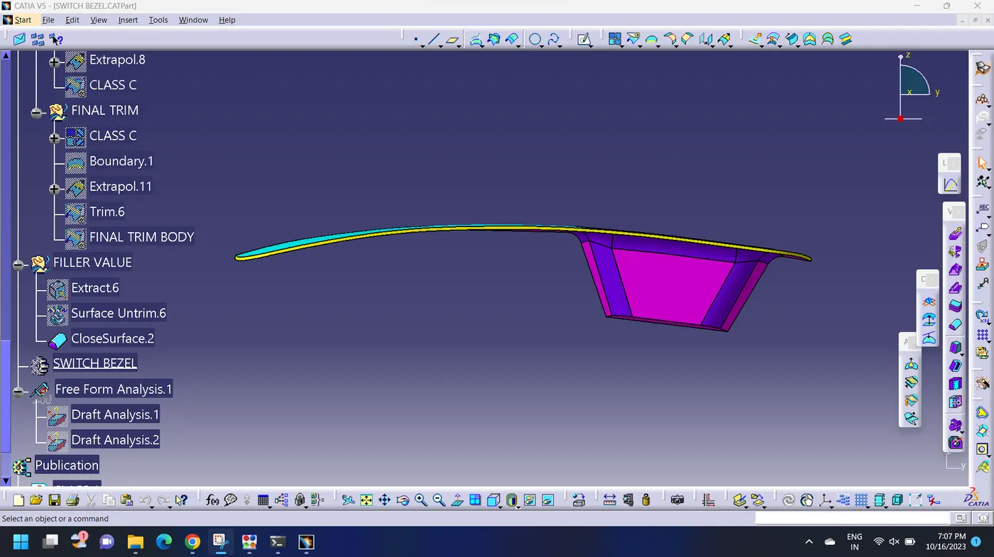
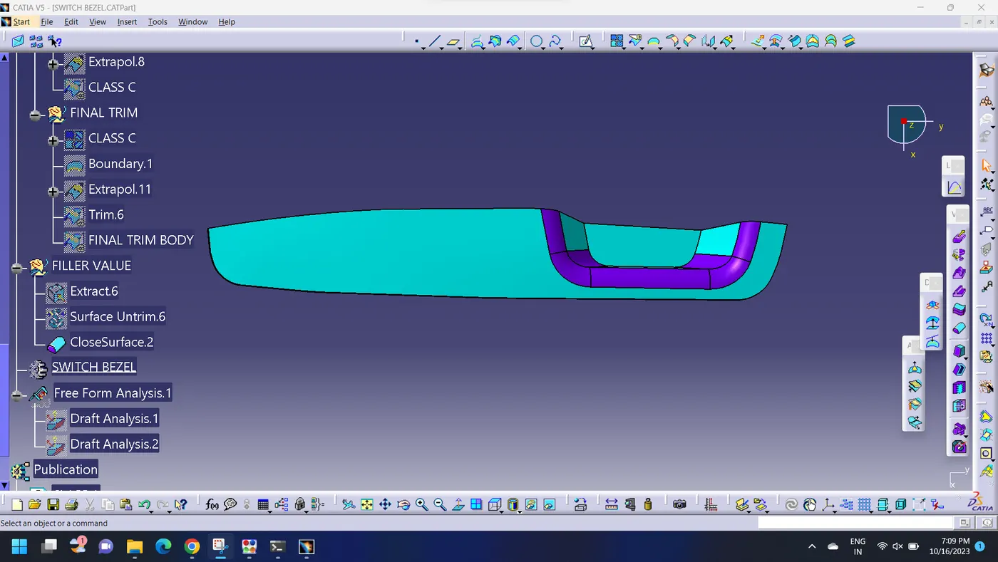
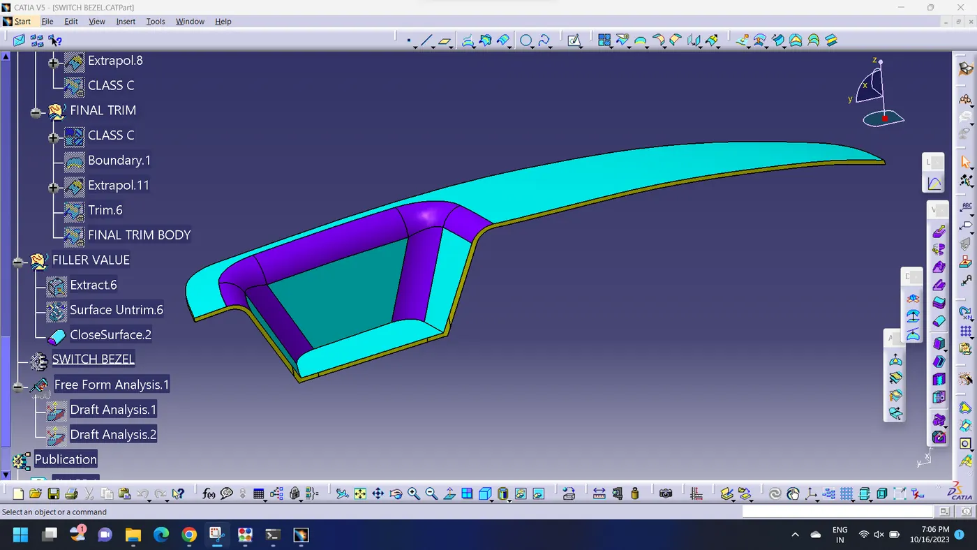
Final Component Closed body in Various Orientations: