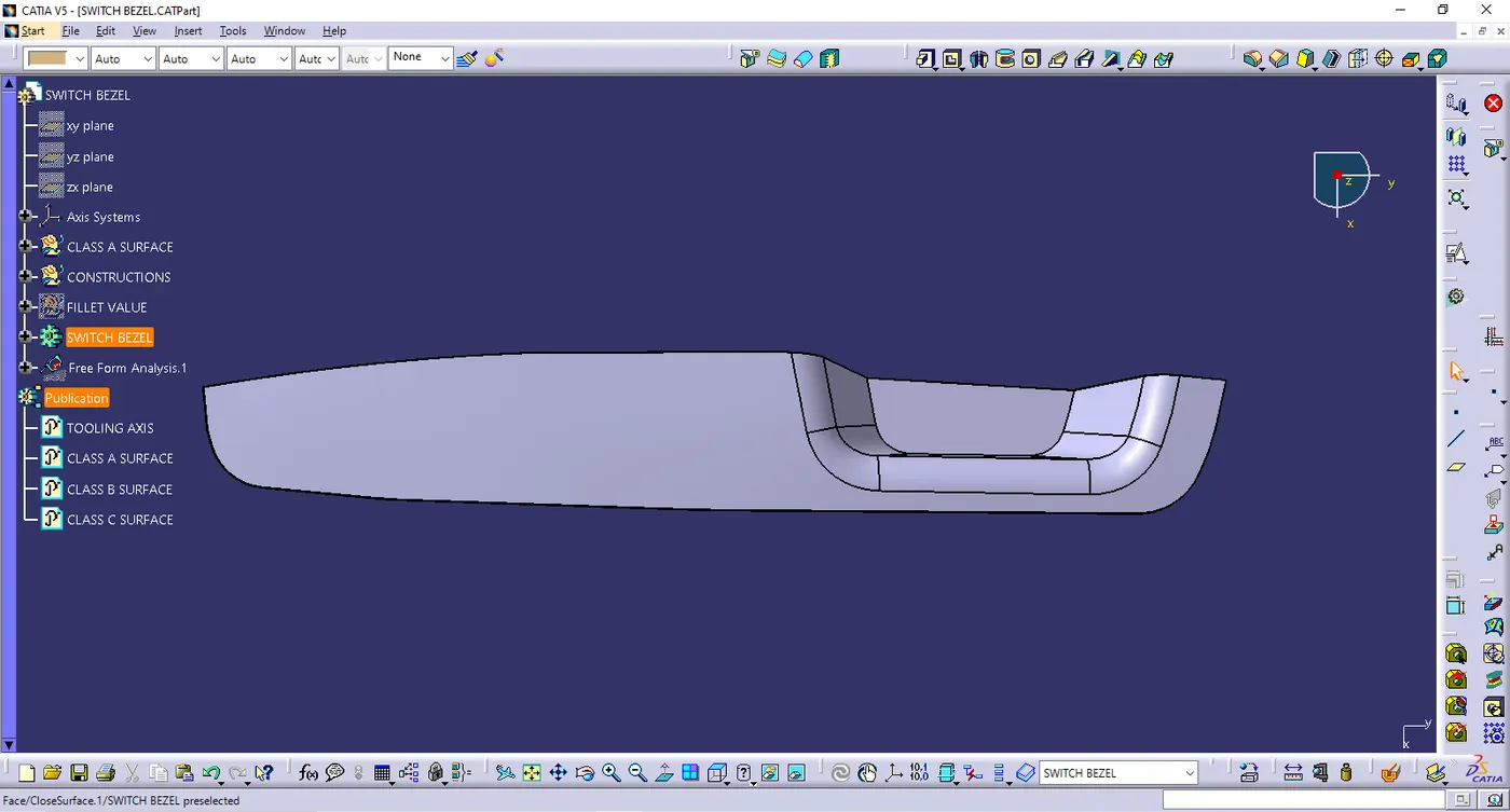
Week 9 - Challenge 2 - Switch Bezel Design
- SWITCH BEZEL DESIGN
AIM : To Create the Switch Bezel Plastic component through the given Class-A surface
- Tooling axis
- Ensure the class A surface is properly joined
- Analyse which direction is suitable for tooling axis
- Extract the base surface of the Class A surface. create a point at the center & insert the axis system
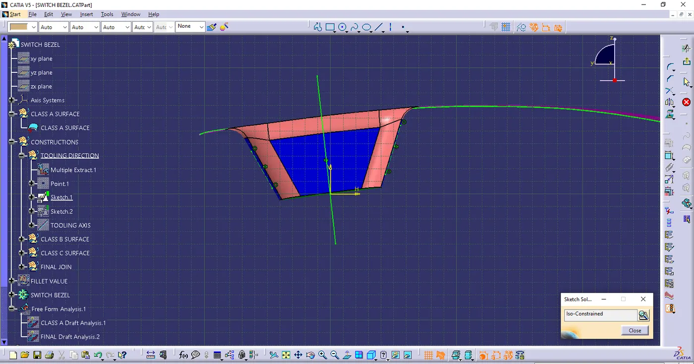
- Click positioned sketch along YZ plane. Two inclined lines are drawn with the help of intersect method
- Bisecting line was created with the inclined lines
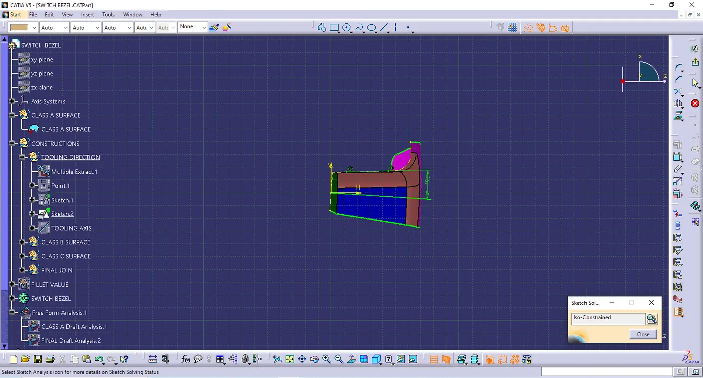
- Again postioned sketch along ZX plane. one inclined line was drawn with the help of intersect method & center line was created with an 5 degree angle because there is no another side
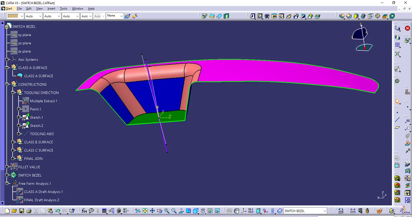
- Finally created the tooling axis with help of Sketch 1 & Sketch 2 & point by bisecting line method
- Class B surface
- Extract the bezel rest surface, walls & base
- Untrim & extrapolate each surfaces
- offset it with the given thickness value & trim the offset surfaces
- Extract the fillet faces & untrim it to find the fillet value
- Once fillet value is given ensure it is in uniform thickness.
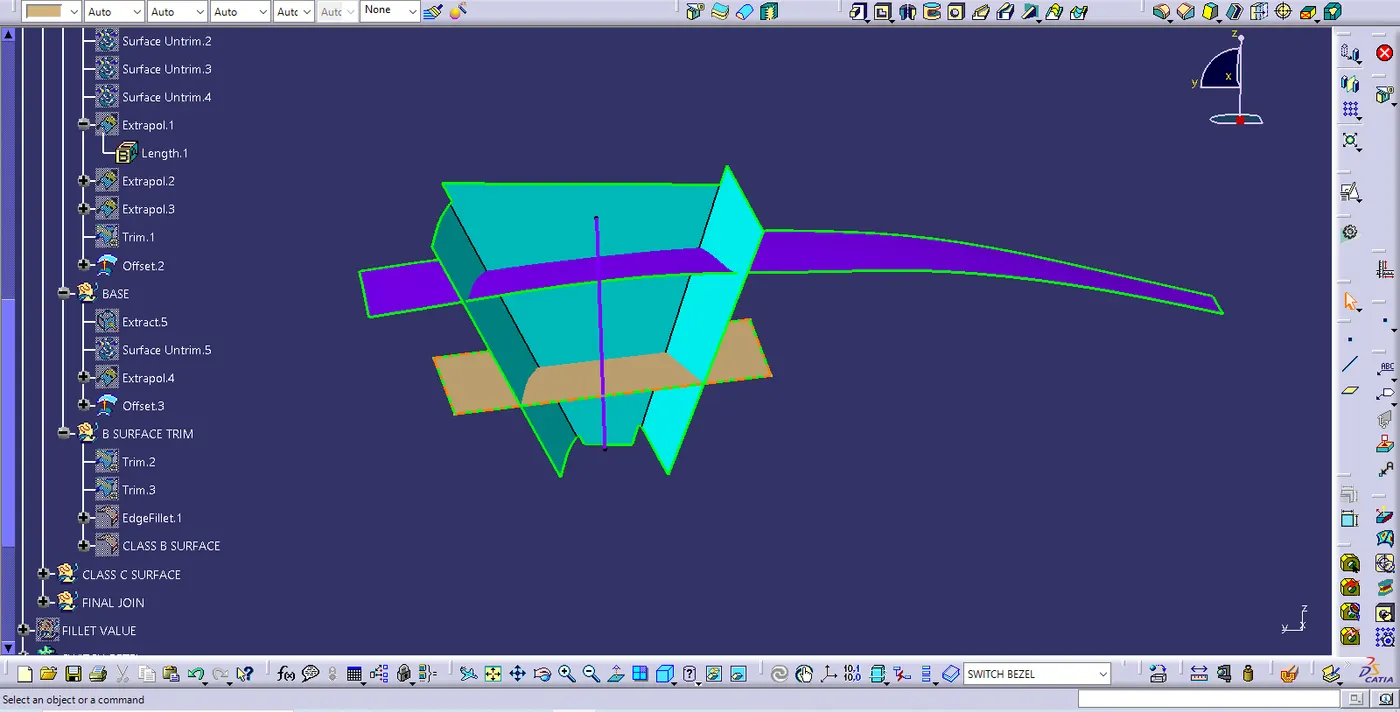
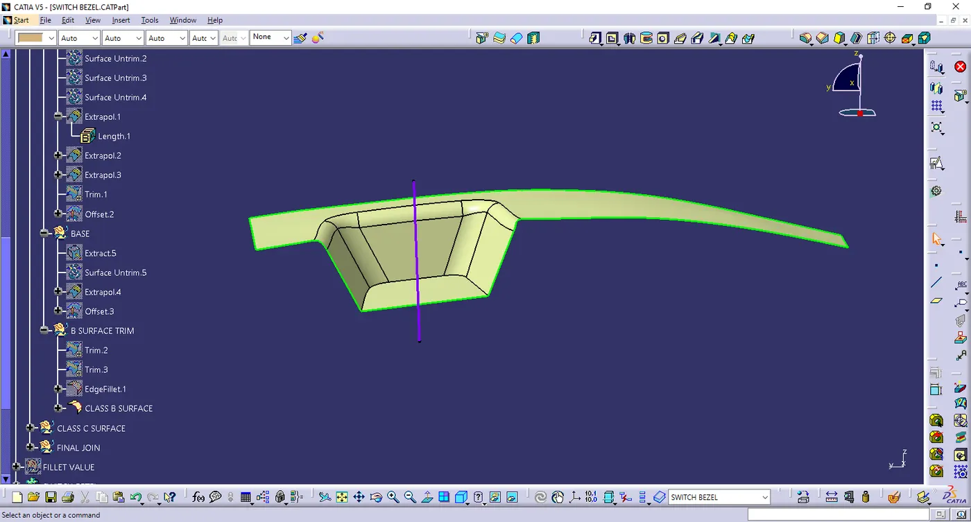
- CLASS C SURFACE
- Click multiple extract & extract the edges of the given Class A surface & it is converted into smooth curves
- Sweep option is performed with the help of draft direction by selecting the smooth curves & the draft angle was 3 degree
- Extrapolated the edges & trimmed it.
- Joined the class A & c. Incread the merging distrance is 0.003mm
- Still one boundary presend there. So, extrapolate the class A with minimum value 0.05mm & trimmed it with class c
- Finally closed suface is obtained with the join & trim command
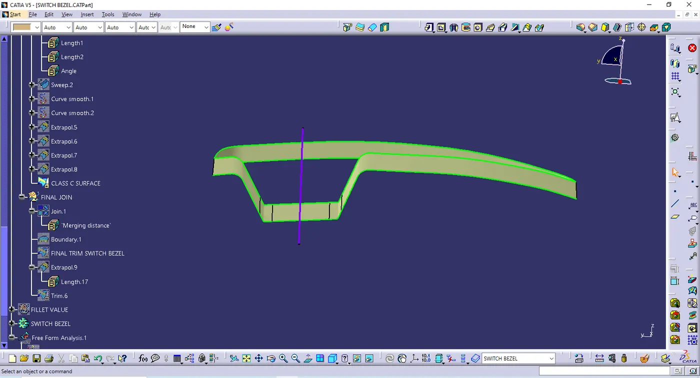
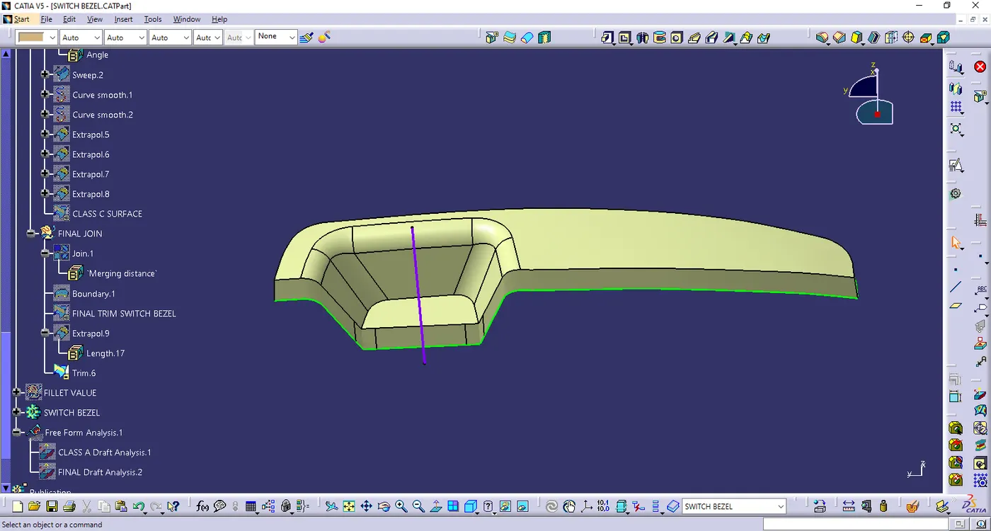
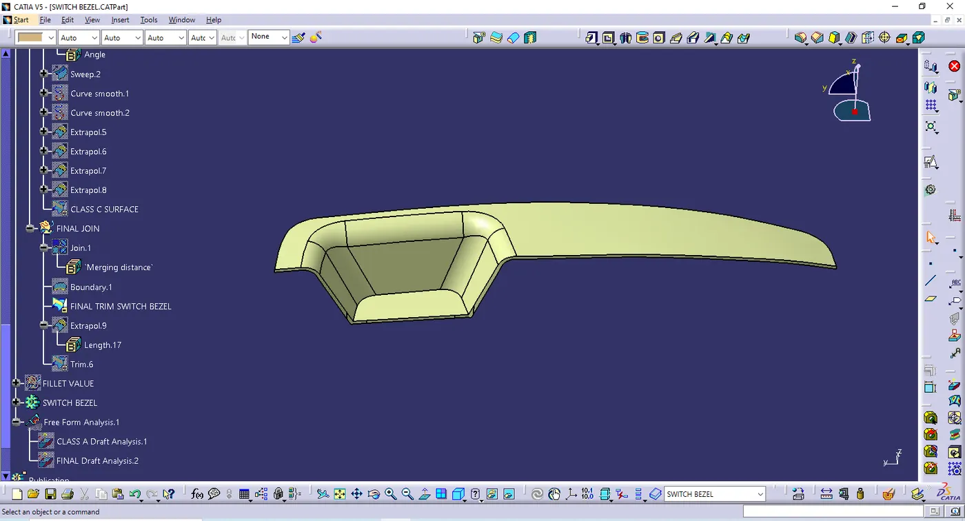
- Draft analysis on Class A surface
- Ensure the view mode in material
- Use the compass to define the new current draft direction & place it on the Tooling axis & lock it
- Click the Class a surface it shows the Green colour area it satisfies with 3 degree
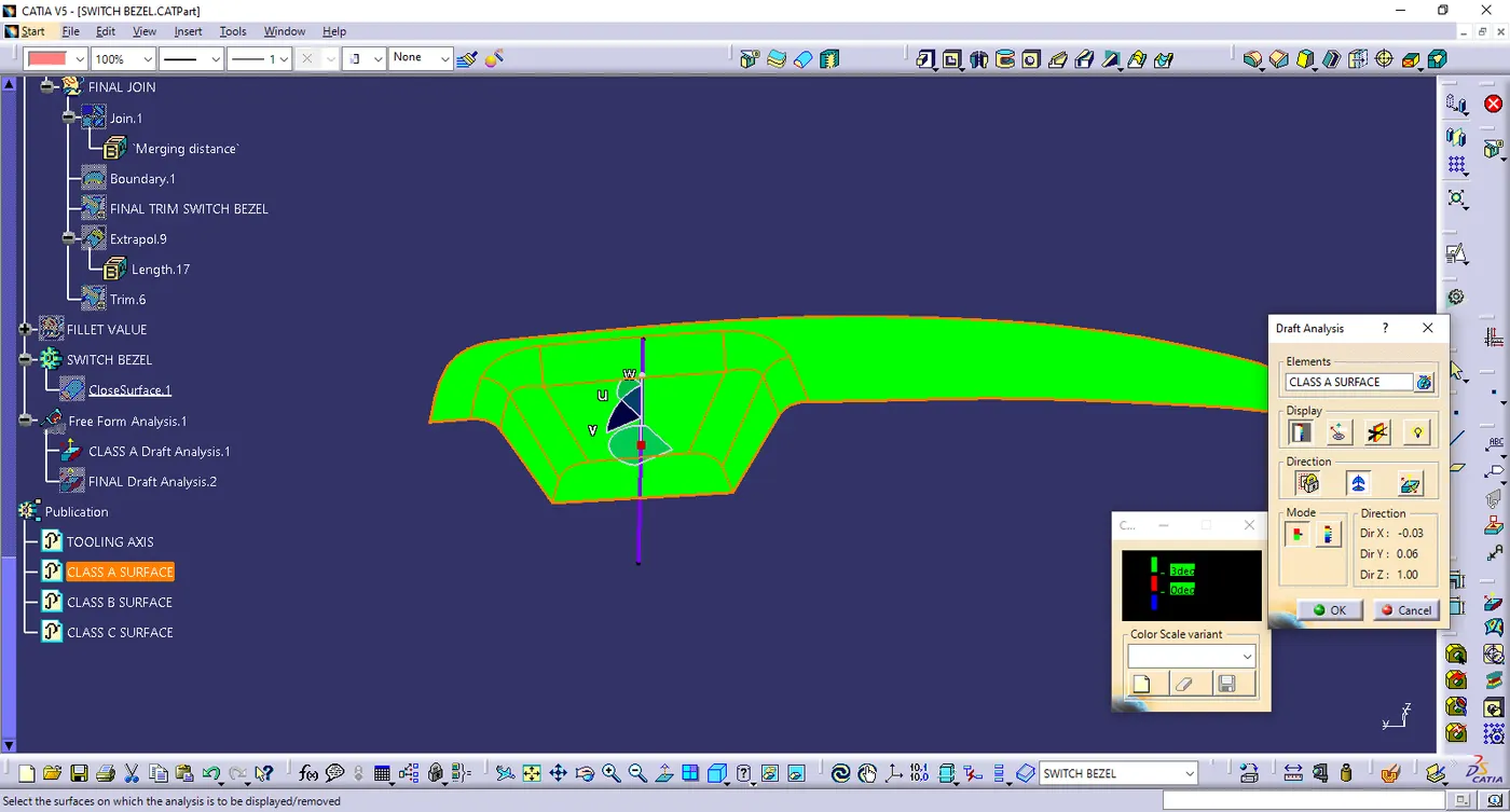
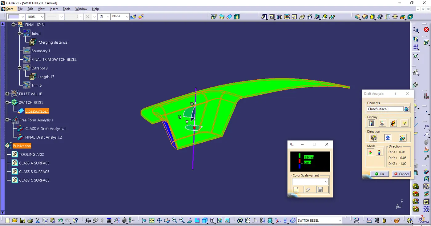
- Draft analysis on Final component
- Ensure the view mode in material
- Use the compass to define the new current draft direction & place it on the Tooling axis & lock it
- Click the final componet it satisfied with the 3 degree draft angle. If it not satisfied use the Analysis under running point tool & correct the values of an draft angle & Tooling axis
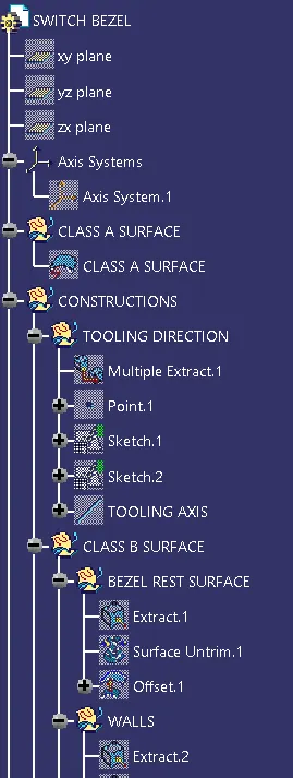
- Tree structure
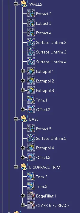
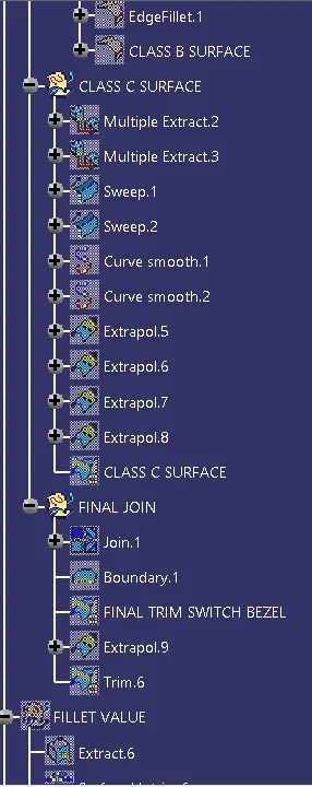
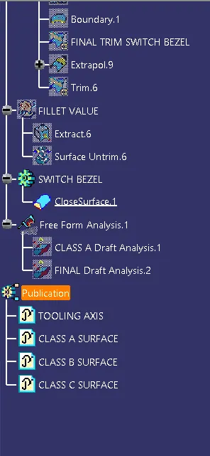
- Close surface feature
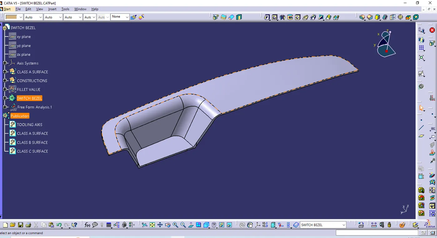
- Isometric view
- Front view
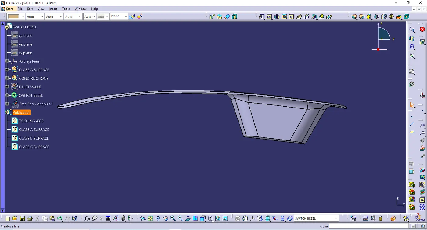
- Side view
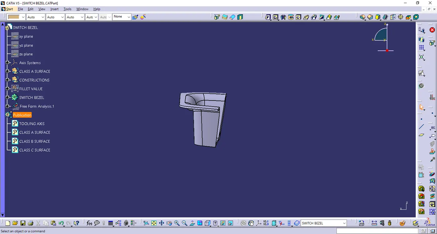
- Top view