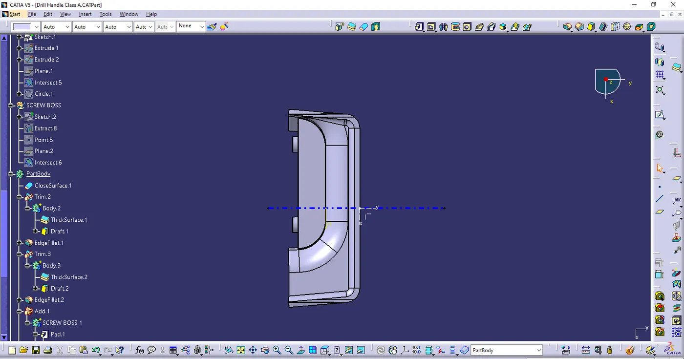
Week 10 - Challenge 1- Attachment Feature Creation (Ribs & Screw Boss)
- DRILL HANDLE DESIGN
AIM : To create the rib & screw boss for the Drill Handle.
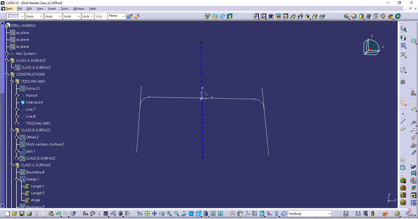
- Tooling axis
- Ensure the class A surface is properly joined
- Analyse which direction is suitable for tooling axis
- Extract the surface, create the point & intersect with class A surface
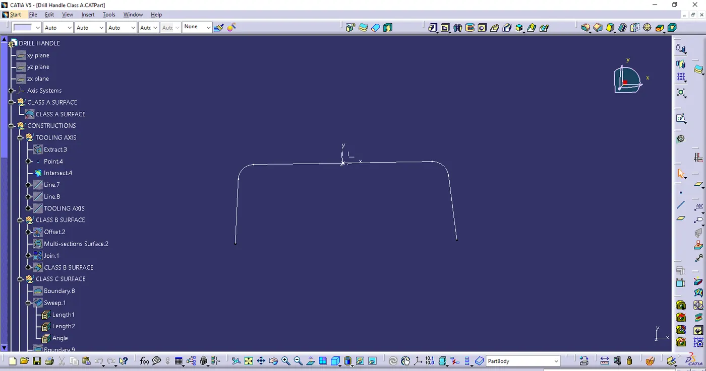
- creating the line with point-point reference on bothsides
- Finally created the biscecting line with help of line 1 & line 2 & point to get the final tooling axis
- Class B surface
- Offset the class A surface in 2.5mm in proper direction
- Once offset is done some patches are missing
- Then missing patches are obtained with the help of Multi sections, join & extrapolate commands
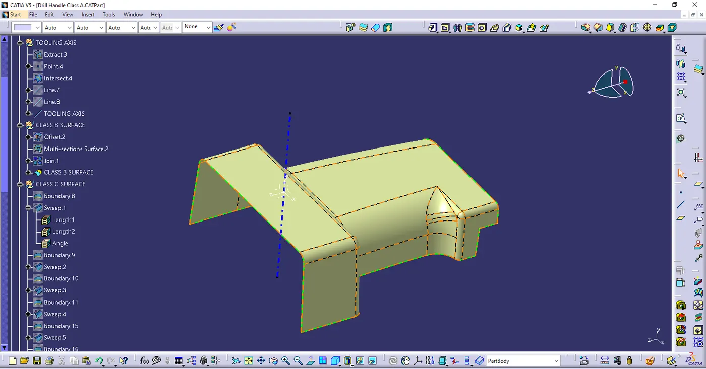
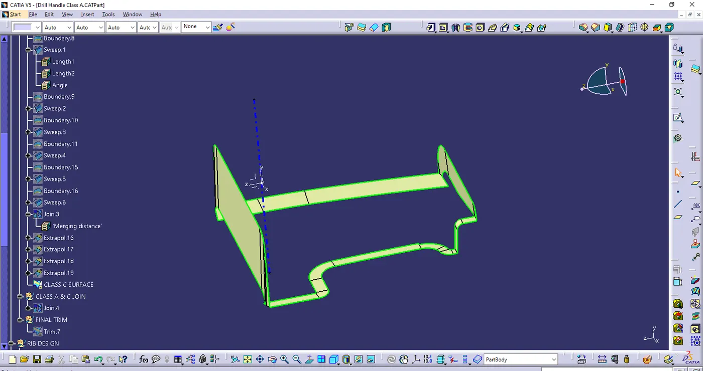
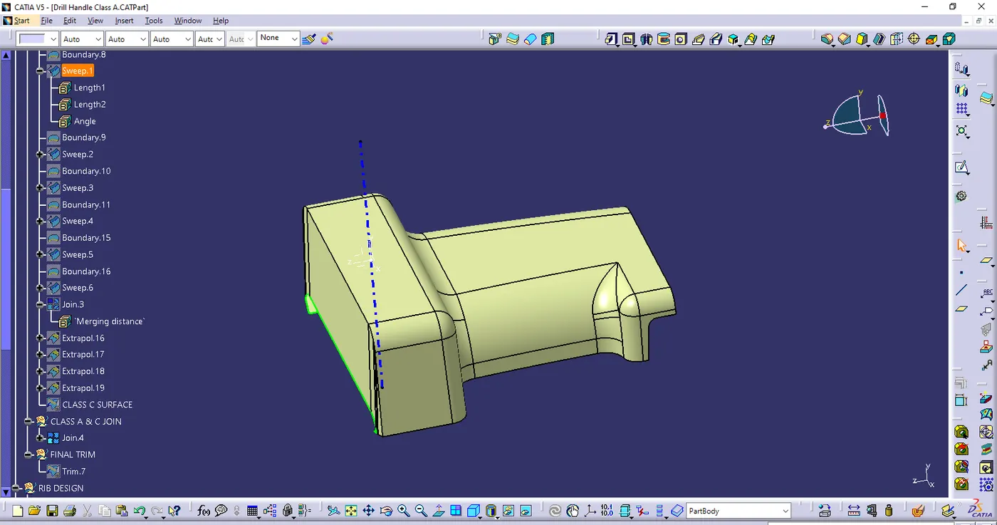
- CLASS C SURFACE
- Create seperate boundaries from one vertex to another vertex in the class A surface
- In sweep command with draft direction 3 degree was given to the boundaries with the help of tooling axis
- In sweep command with reference surface 90degree was given to the boundaries
- Then extrapolated the edges & trim it
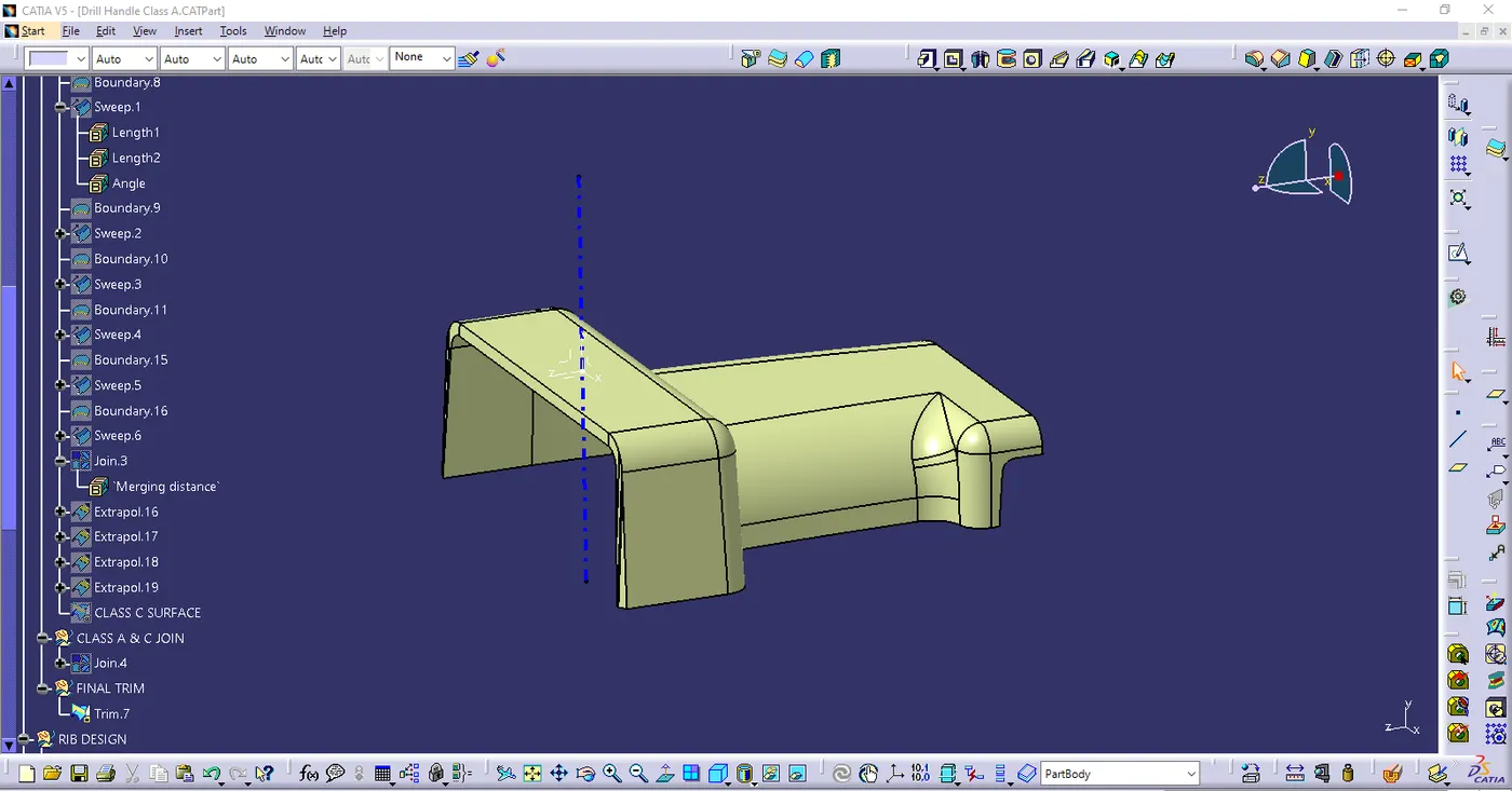
- Join the Class A & C surface together
- Finally closed suface is obtained with the trim command
- Sketch for Ribs
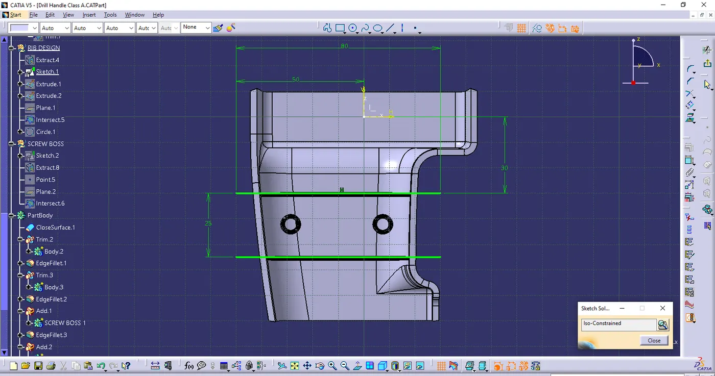
- Sketch for Screw Boss
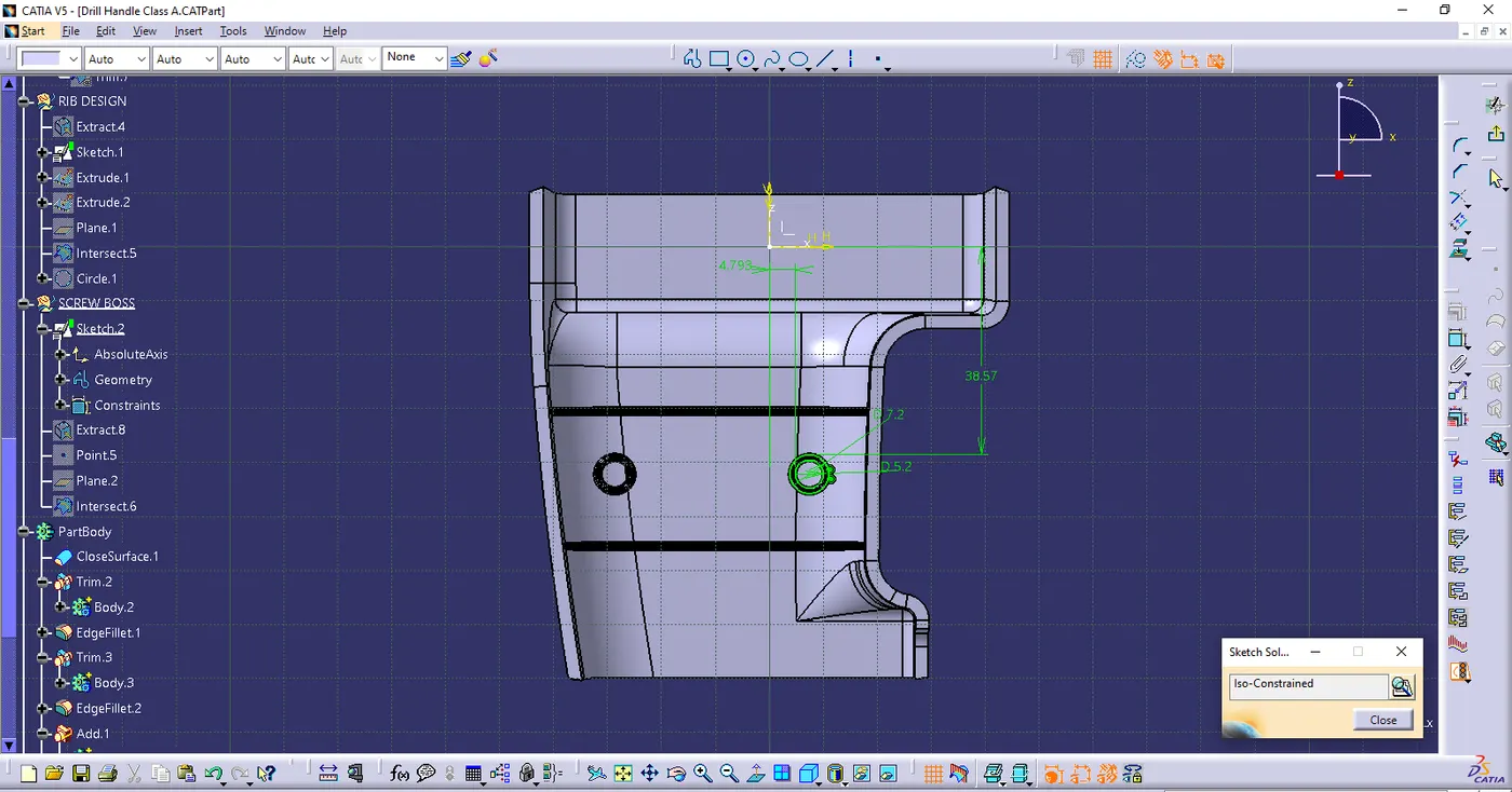
- Analysis for Rib creation
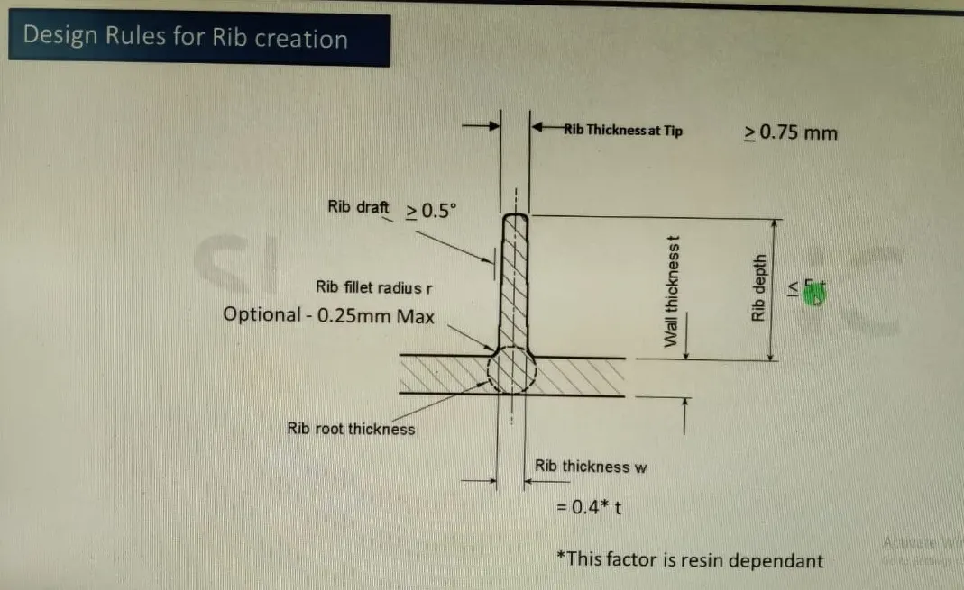
- Both ribs are cretaed based on th design rules
- Positioned sketch was created. Extrude & thick surface commands are used as per the rib design rules
- After providing the draft. Boolean operations are used to add it to the body
- finally fillets are given.
- Analysis fo Screw Boss
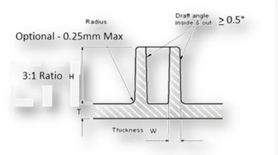
- Both Screw Boss are cretaed based on th design rules
- Positioned sketch was created. Pad & Drafted with the Screw Boss design rules
- After providing the draft. Boolean operations are used to add it to the body
- Fillets are given.
- Finally using the translate comand to created the second screw boss
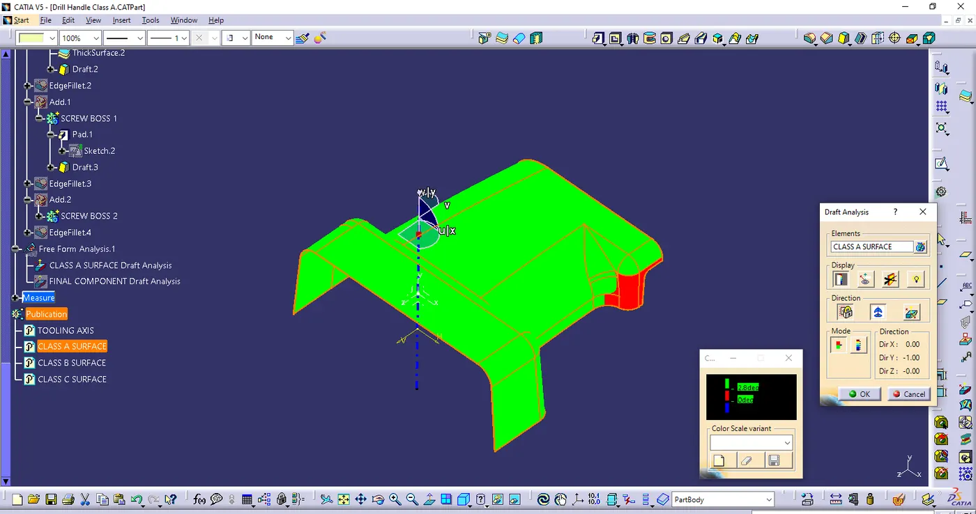
- Draft analysis on Class A surface
- Ensure the view mode in material
- Use the compass to define the new current draft direction & place it on the Tooling axis & lock it
- Click the Class a surface it shows the Green colour area it satisfies
- In this Class A surface some surface are not satisfied. So it needs to correction in the Class a creation team.
- Draft analysis on Final component
- Ensure the view mode in material
- Use the compass to define the new current draft direction & place it on the Tooling axis & lock it
- Click the final componet it satisfied with the proper draft angle. If it not satisfied use the Analysis under running point tool & correct the values of an draft angle
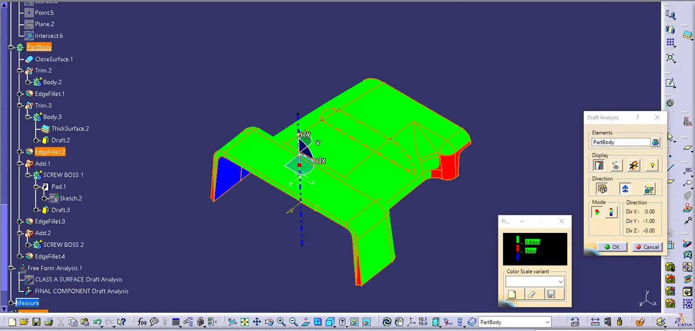
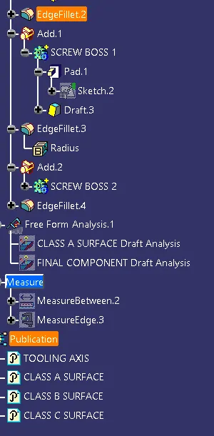
- Tree Structure
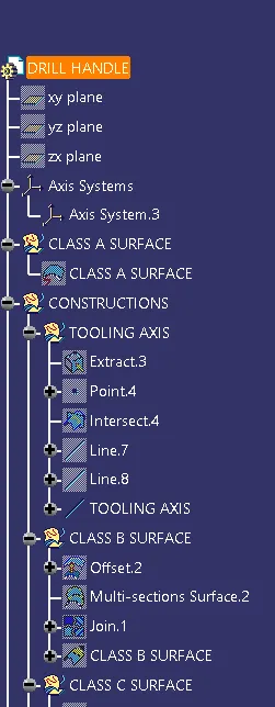
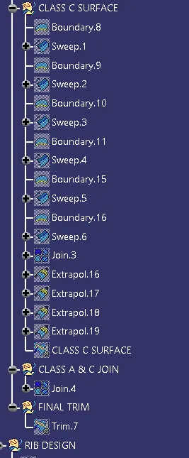
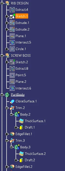
- Close surface feature
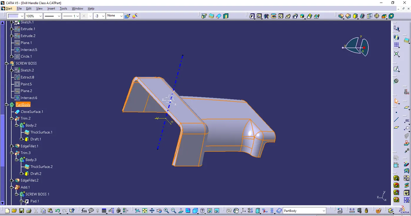
- Isometric view
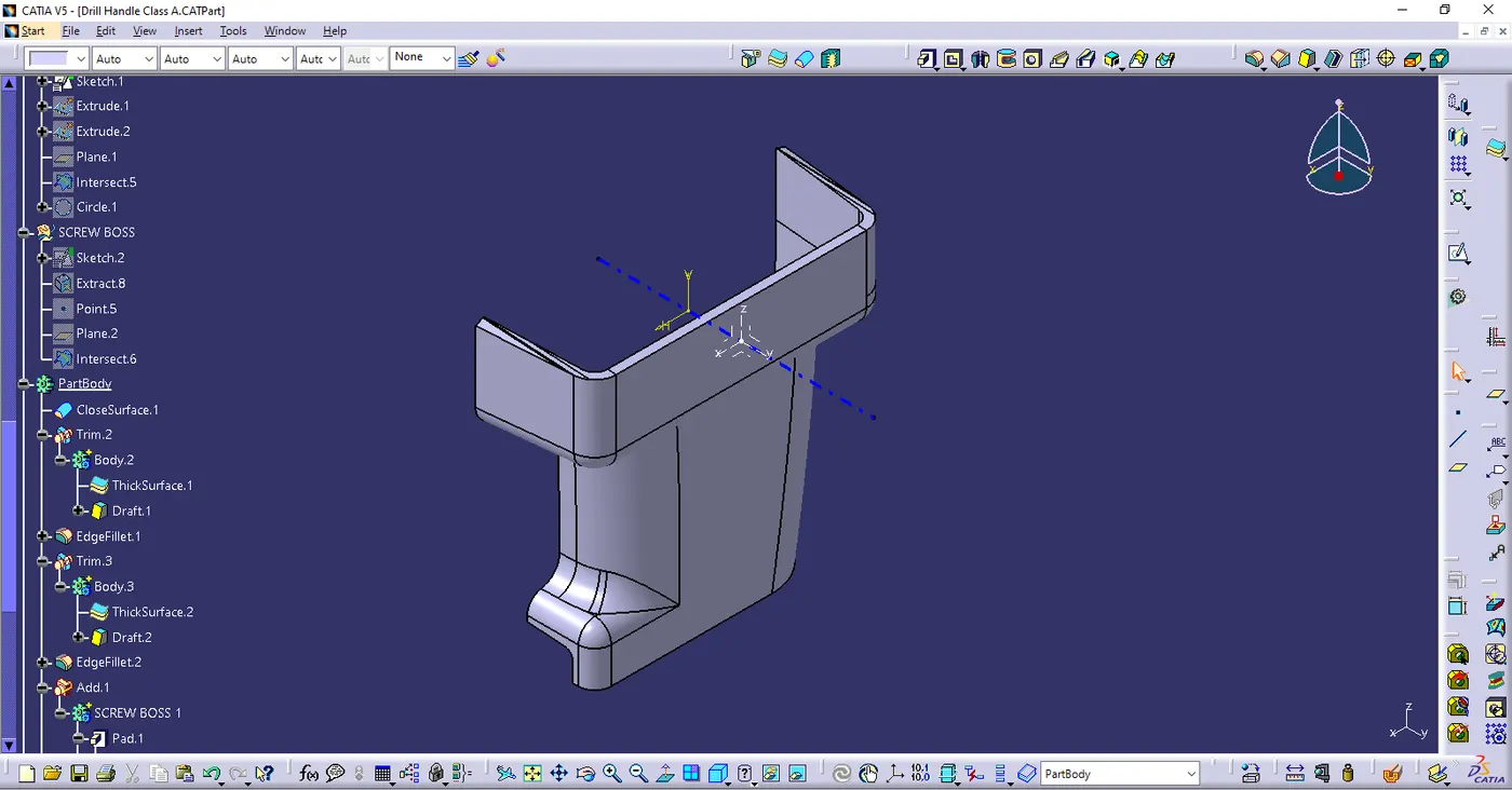
- FRONT VIEW
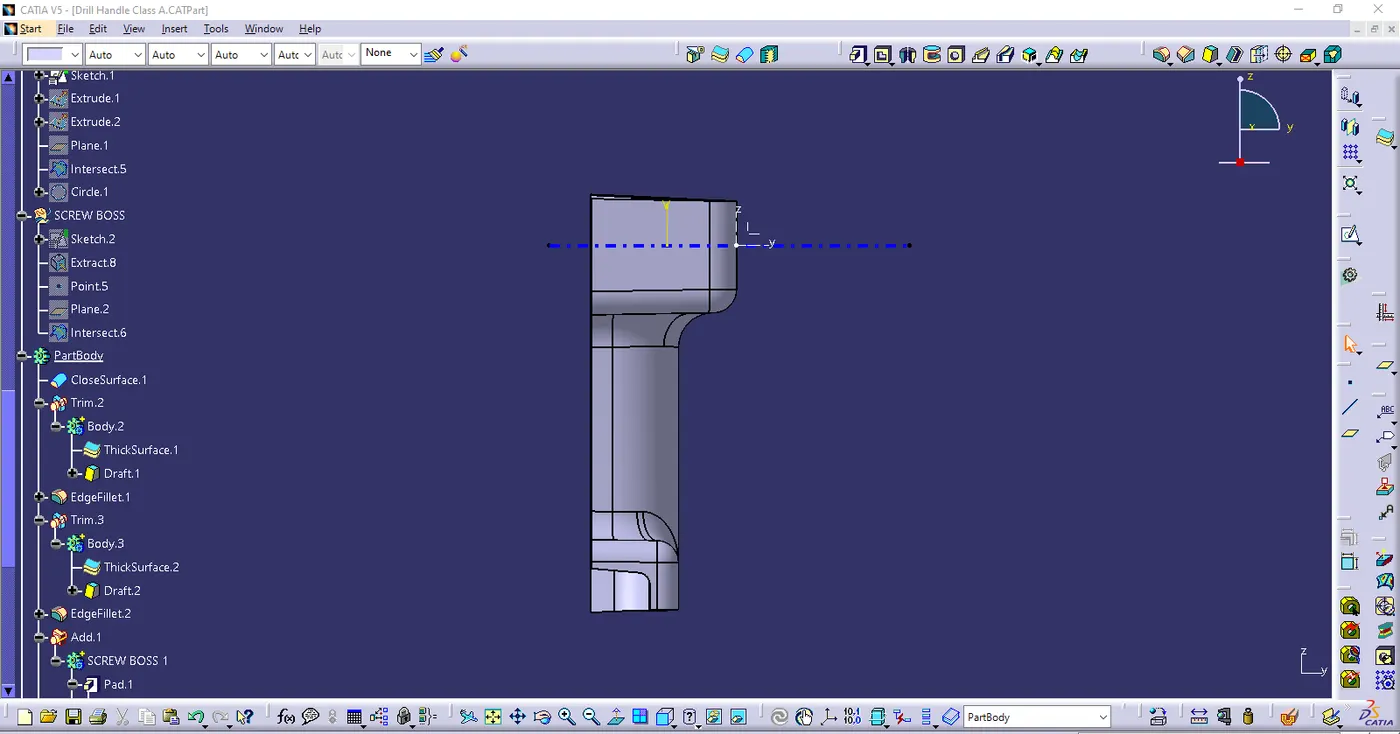
- SIDE VIEW
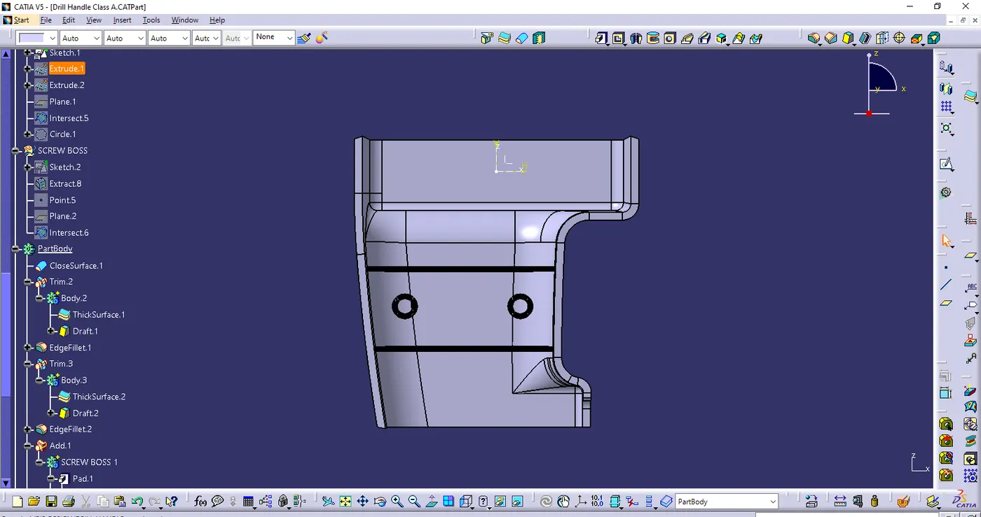
- TOP VIEW