Week 9 - Challenge 2 - Switch Bezel Design
tOOLING AXIS
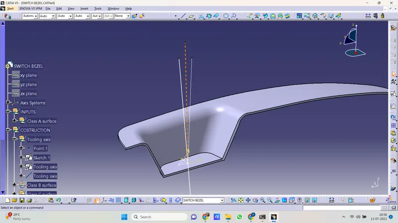
The tooling axis is established through the implementation of the bisection method. By intersecting in the y-direction, two lines are formed within the inclined area of the part. Subsequently, by bisecting those two lines, the tooling clearance in the y-direction is generated. Moving on, an intersection is made in the x-direction, where one line is drawn from the inclined side, while the other line is created at a certain angle. Through the bisection of these lines, the tooling clearance in the x-direction is determined. Finally, the tooling axis is obtained by bisecting the tooling clearances in both the x and y directions.
DRAFT ANALYSIS
The draft analysis serves to determine the required draft angle for the part, enabling its smooth rejection or ejection from the mold. The minimum draft angle permissible is 3 degrees. In the provided part, the color green indicates a draft angle of 2.9 degrees, while the color red represents a negative value, indicating an insufficient draft angle.
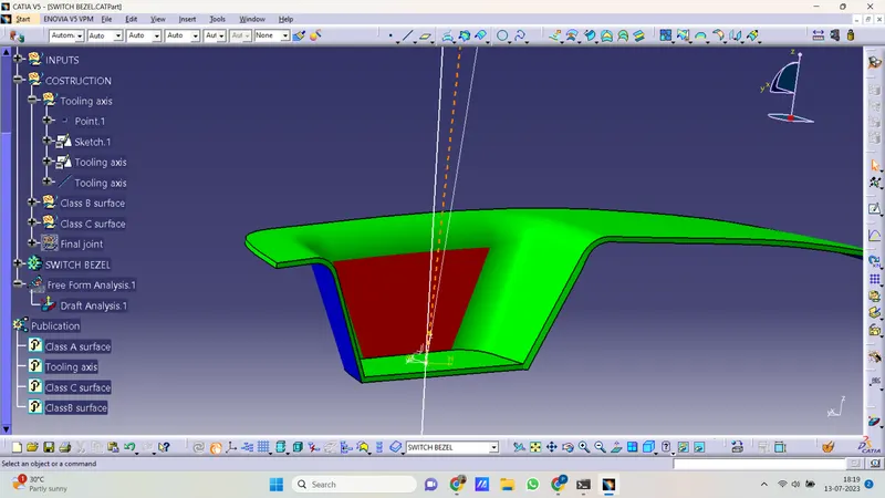
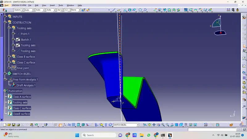
NOTE:- I am creating proper tooling direction but still one face is showing a less draft angle than 3 which is highlighted in red color.
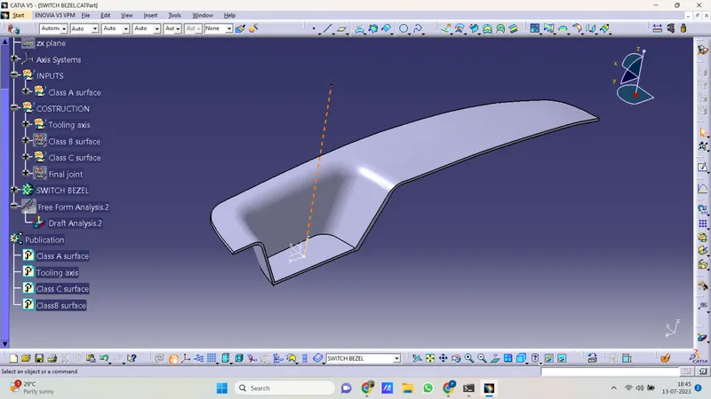
Isometric view:-
Front view:-
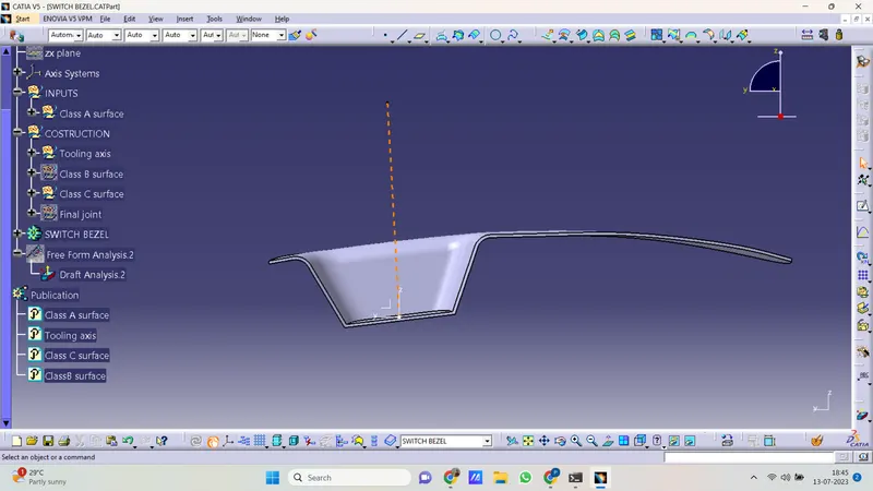
Side view:-
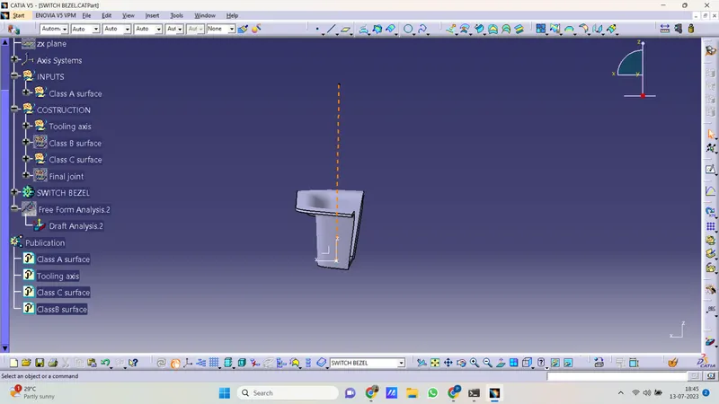
Top view:-
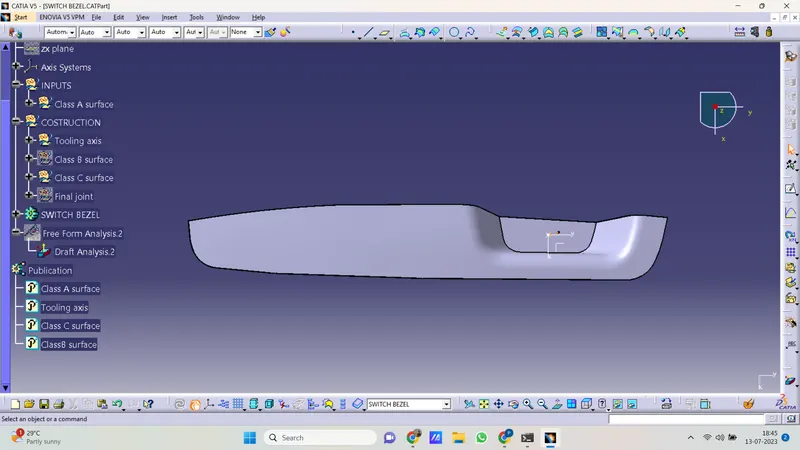
Tooling axis:-