Week 9 - Challenge 2 - Switch Bezel Design
SWITCH BEZEL
Switch Bezels in car are parts which contains switches and controls for different functions like Window control, Door lock/Unlock,Media and Temperature controls.
DESIGN CONSIDERATION
It consist of three surface
- Class A surface
- Class b surface
- Class c surface
TOOLING DIRECTION
Basically the mould has two seperate parts core and cavity ,in that tooling direction means that mould pulls a part from the cavity
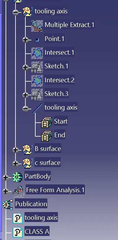
CREATION OF TOOLING AXIS
Extract the base surface for creating the tooling axis
plot the point on the surface ,for create bisecting line
create a axis system for our reference .
select a positioned sketch with the reference of yz plane in reverse direction
create a intersection along the yz direction
Draw the line based on the refer of intersection sketch and also make constraint
create a bisecting line based on the above reference line
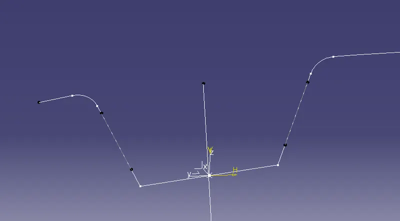
Same as the creating the another reference line using the xz axis
create a intersection based on xz axis ,and also create a line using positioned sketch
create a another line based on previous line the anle between the line is 6 degree
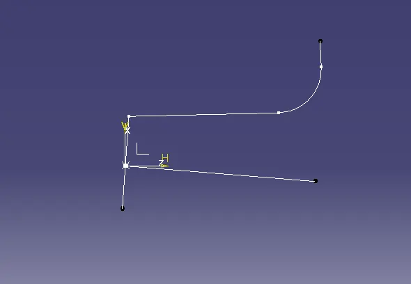
Finally using a line command ,to create a bisecting line with the reference of above two lines
DRAFT ANALYSIS
A draft analysis is used to see if the draft of a part is sufficient for the molding process and if the part will separate correctly from the mold
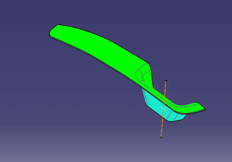
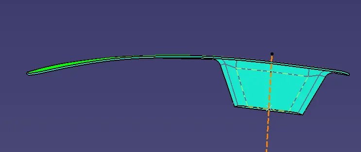
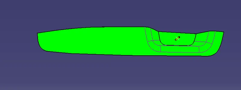
For draft analysis first fix the direction of tooling axis and then next select the surface
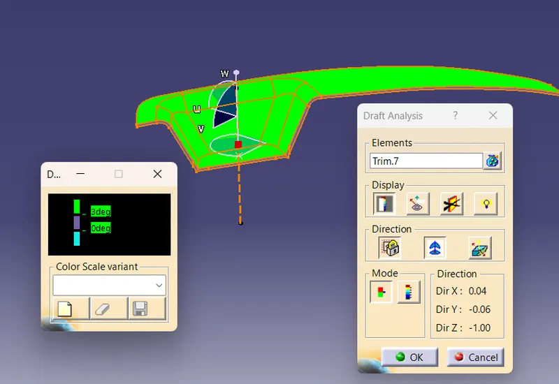
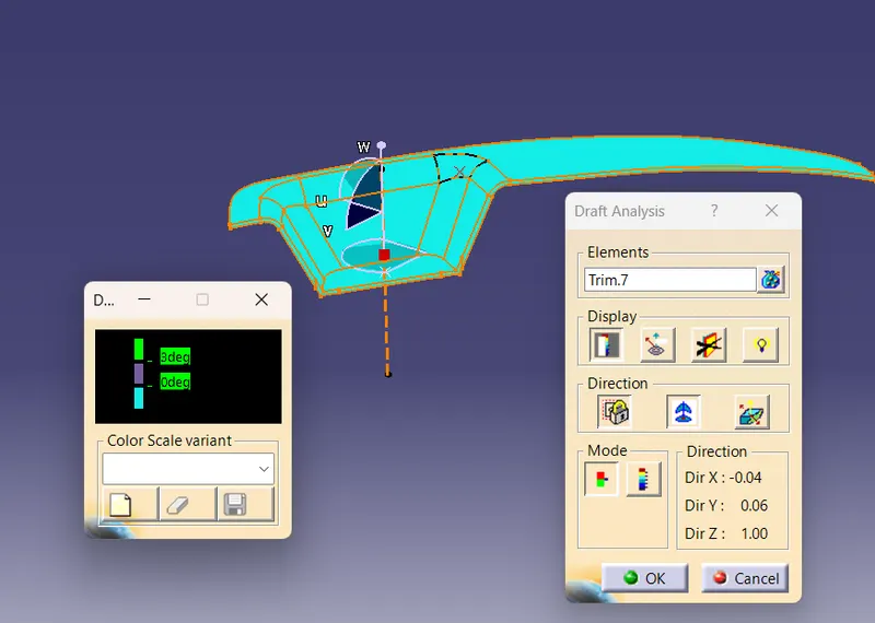
ISOMETRIC VIEW
FRONT VIEW
SIDE VIEW
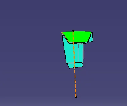
TOP VIEW
CLASS B SURFACE
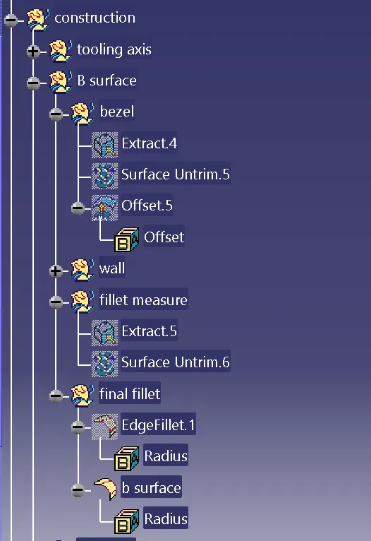
- Extract the upper surface of the switch bezel and untrim the surface to reach the original shape
- To create a offset of 2.5mm of the required thickness
- To make a offset of the inner surface and also untrim the surface
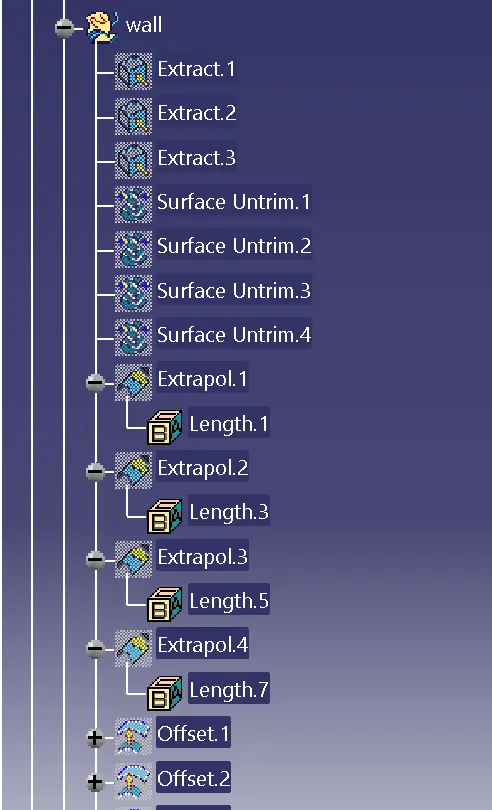
- Extrapolate the surface to make a required surface
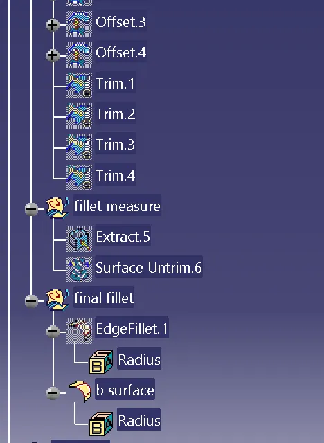
- Trim the unwanted surface to make a class b surface
- measure the fillet value and also calculate offset fillet value
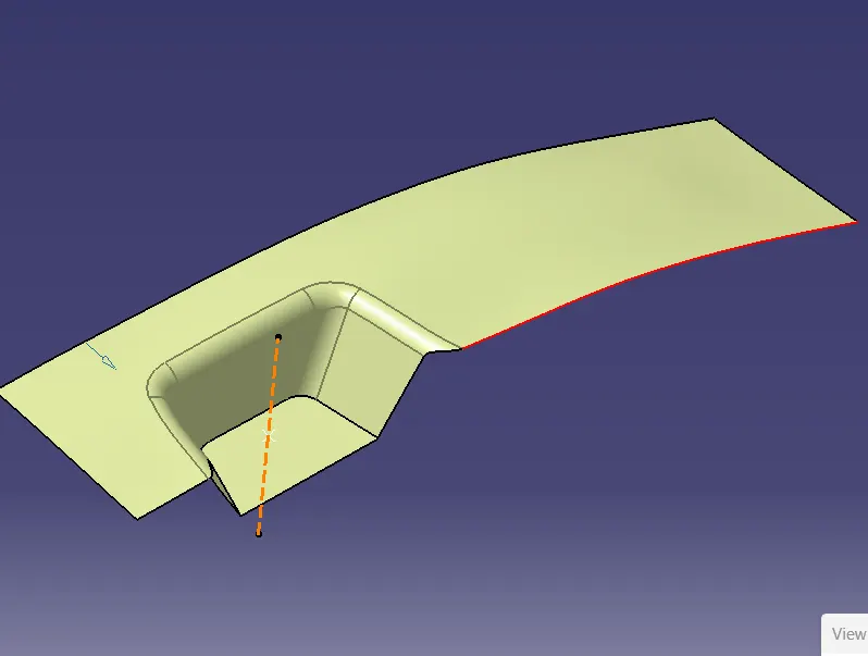
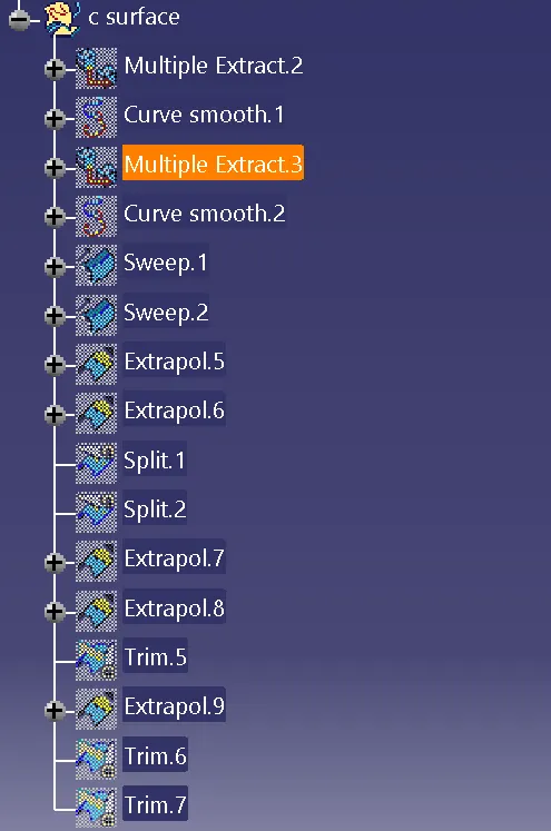
CLASS C SURFACE
- To create the boundary of the surface using the multiple extract command
- Extrude the boundary surface using the tooling direction
- smooth the extrude surface using curve smoothen command
- Extrapolate the corner of the surface of the unjoined surface ,to trim the unwanted surface
- join the surface using surface A and surface C
- To trim the unwanted surface using the bsurafce as a reference
CLOSED SURFACE
After creating the surface ,to make a closed surface using the part body tools
TREE STRUCTURE
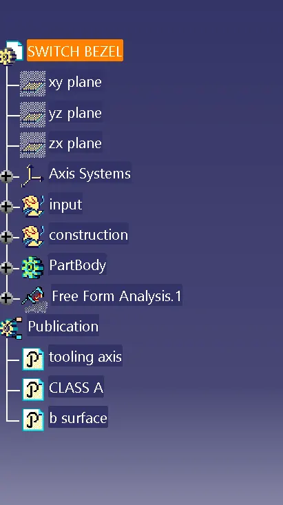
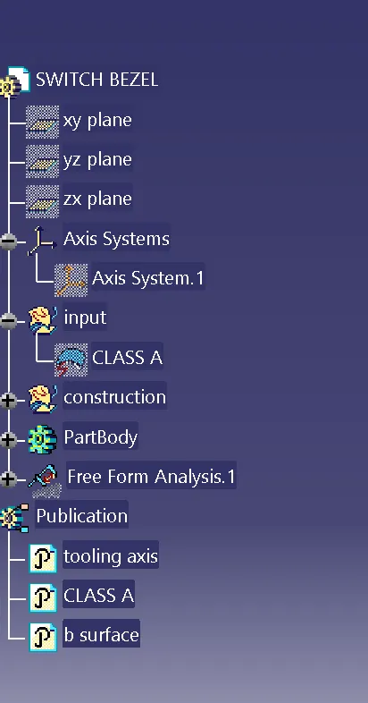
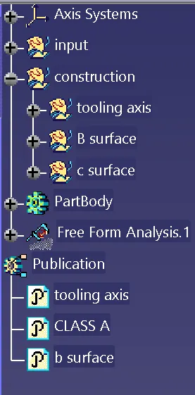
CONCLUSION
Finally the class A ,ClassB,class C surface and tooling axis created and also subjected to the draft analysis for the switch bezel .