Week 9 - Challenge 2 - Switch Bezel Design
To create the Switch Bezel Plastic component the following steps have been followed
- Creating Tooling axis and performing draft analysis for given model
- Creating Class B Surface from class A Surface
- Creating Class C Surface .
- Creating a solid body using close surface command .
- performing a draft analysis for the final model
Before creating any component we have to Check input surface of the Class A surface for continuity and repair any discontinuity like breaks and disjoints.
Creating Tooling axis and performing draft analysis for given model:
The tooling direction is biscally the direction that the mold pulls apart.The mold is built in two separate pieces,basically.You have a cavity side and you have the core side.The core pulls apart from the cavity and that's the tooling direction.There are different methods to find out the tooling direction .Here we are using bisecting method to find out tooling direction.
THe depressrion in the class A will be a reat palce to star the tooling asix base as it can form the cavity part so Extract the base surface of the given Class- A Surface and create the center point of the Extracted surface.and insert a axis system to create the geometery for the tooling direction
we wil create a sketch in x direction to intersect the class A with yz plane and obtain a bisectign line that bisects the two walls of the classA surface in thisdirecton.
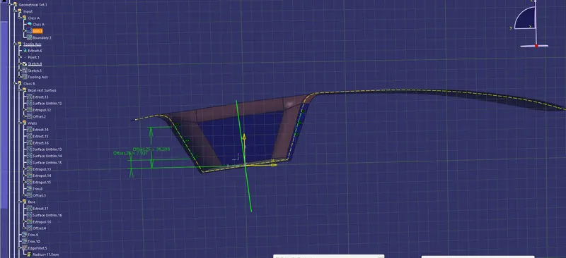
now we can create a simila skect in y direction to intersect the xz plane but we only have a single wall in this direction so we create a dummy line form the origin of the skect at 3 deg form the single wall.
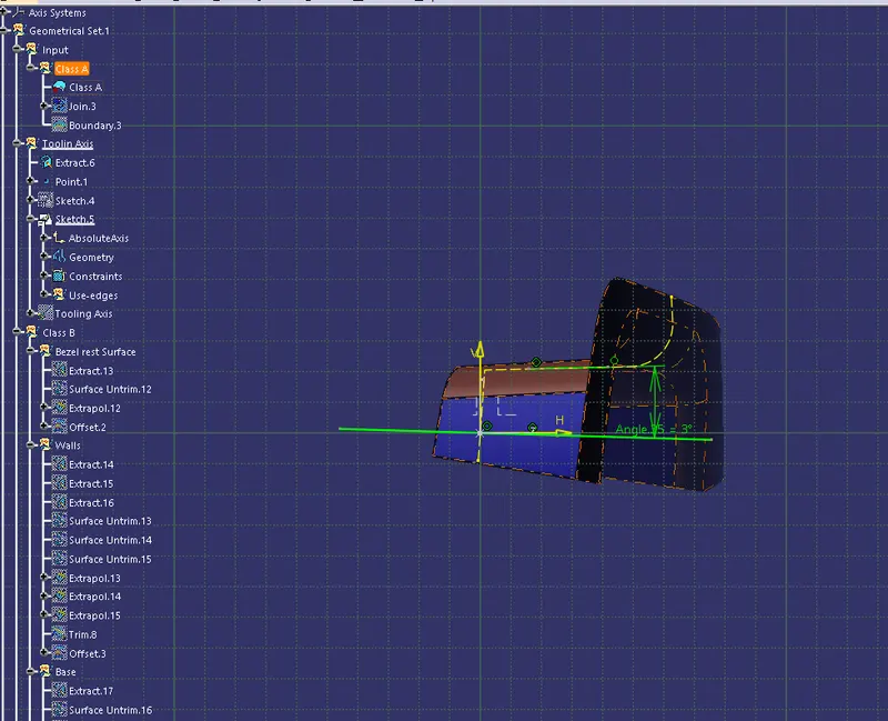
we will crate a line that bisects these two resulting sketches to createt the tooling Axis.
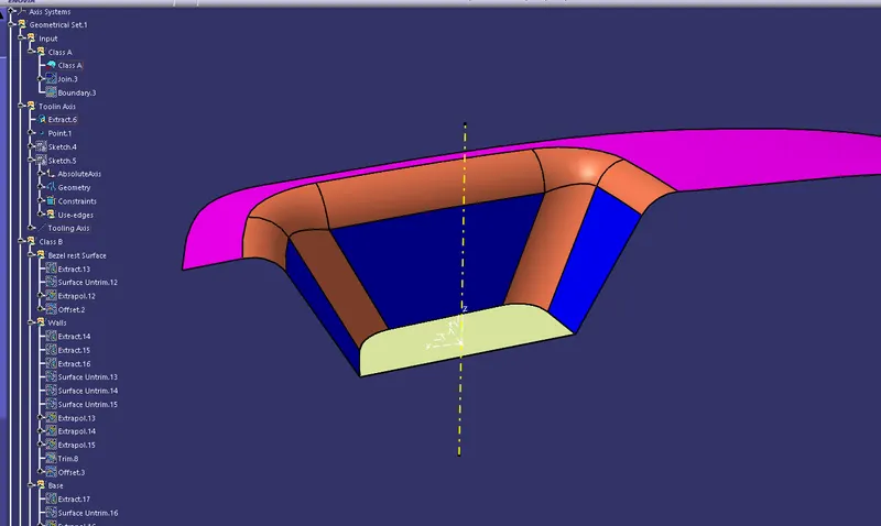
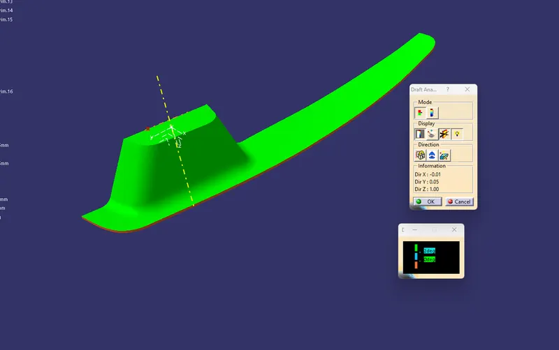
A draft analysis in performed on the Class A Surface and it isnoted that 2 deg of draft is okay for this surface.
Creating Class B Surface from class A Surface:
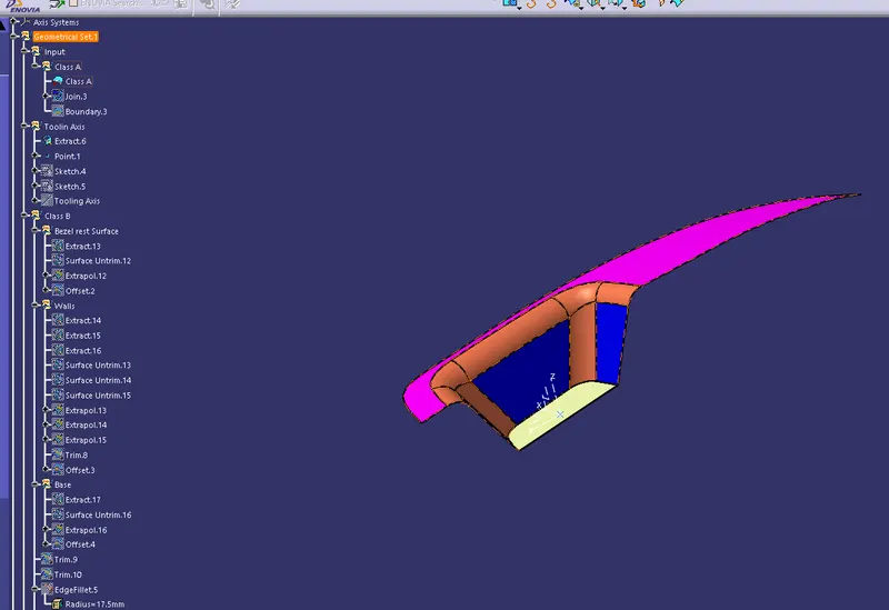
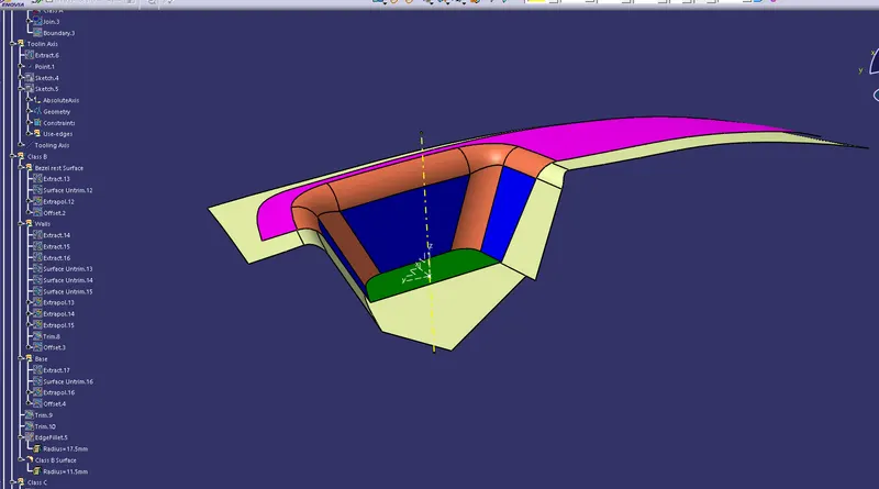
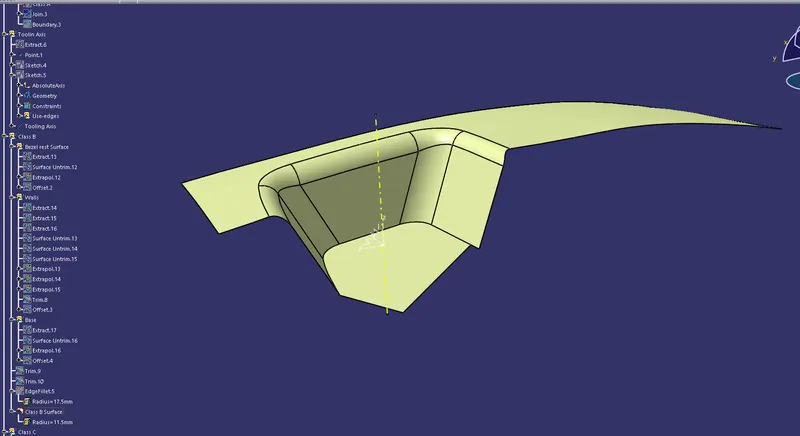
The Class B surface is the surface of the component that decides the thickenss od the component and is an offset of the high defenition class A surface. Typcally class B surface is obtained by offsetting the class A surfcae but care should be taken that the overall thickness remians the same throgh out the component.
The following tree strcutres shows the steps that are included in creating the Bsurface.
Creating Class C Surface:
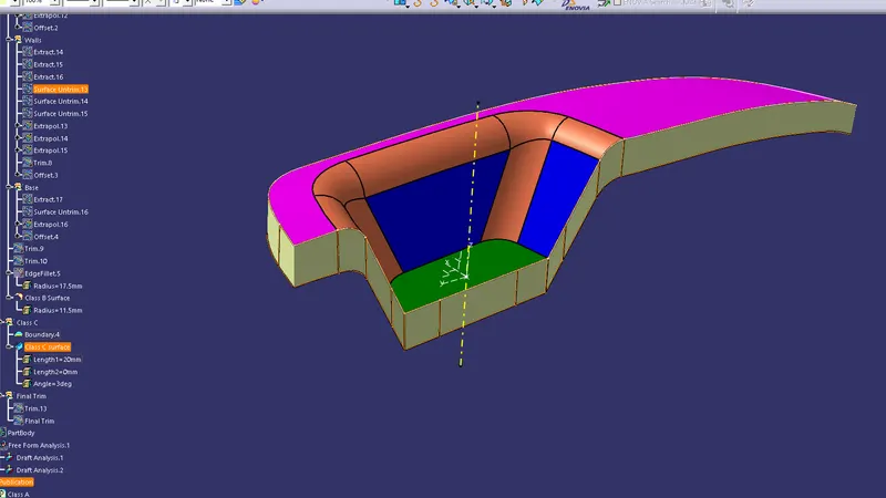
Class C surface is the closing surface that joins the class A surface to the Class B surface. while creating this surface we have to consider the draft to be applied on this surfce as well. we sweep the boundary of the class A with a draft of 3 deg in the tollling direction to obtain the C surface.
The below tree strcuter shows the steps used for creating the Class C surface here
Creating a solid body using close surface command .
The Final trim or the closed volume for the is obtinaed by combining all the 3 surfcaes.
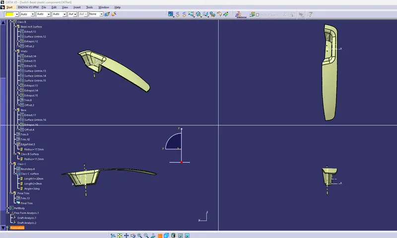
The solid componet is obtined by thickening the closed volume.
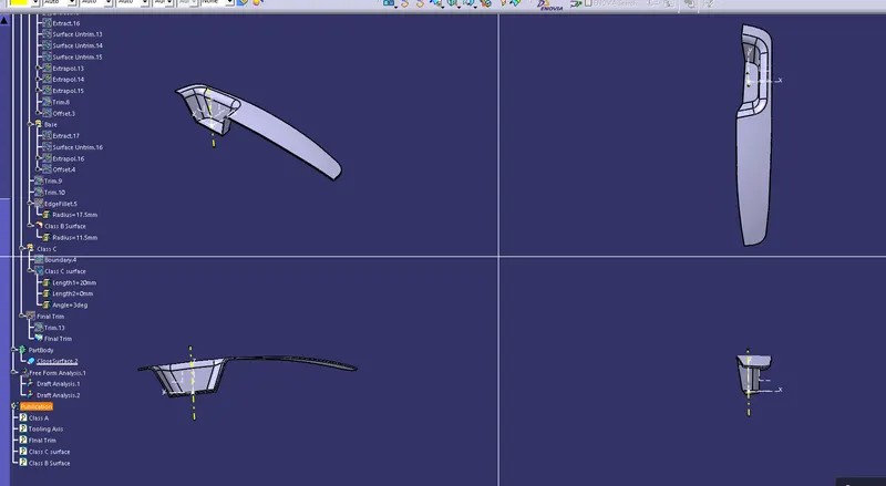
performing a draft analysis for the final model
A Similar analysis method is used as we have perfomed for the Class A surface.we will use the tooling direction and axis to detremine the overall draft on the final component.
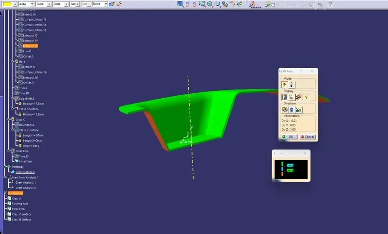
it is agian observed that the 2 deg of draft is okay for the cavity side and we can observe that the core side has negative draft that will clear the tooling if wee inveser the direaction.