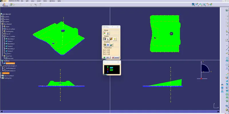
Week 9 - Challenge 1 - Base Bracket Design
Base Bracket Plastic component:
To create the Base Bracket Plastic Componet the following steps have been followed
- Creating Tooling axis and performing draft analysis for given model
- Creating Class B Surface from class A Surface
- Creating Class C Surface .
- Creating a solid body using close surface command .
- performing a draft analysis for the final model.
Before creating any component we have to Check input surface of the Class A surface for continuity and repair any discontinuity like breaks and disjoints.
Creating Tooling axis and performing draft analysis for given model:
A mould is built into two separate pieces, a Cavity side and the Core side. The Tooling Direction is the direction that the mould pulls away from each other. The direction by which the Core pulls apart from the Cavity is called the Tooling Direction.
- Firstly Create a refernce tooling axis and analyse the components and their angle to the reference axis. by checking if the part clears in x ,y or z directions with out any interfernces
- Take an intersection to the part with a perpendicular plane and get a profile of the section.
- Create lines on the angled sections of the part body that could potentially interfere with the draft angle and tooling direction on both sides of the part.
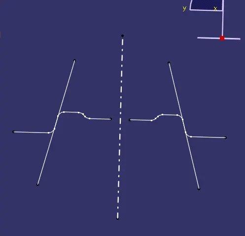
- Create a bisecting line to the two or more lines produced from the angled surfaces. This is the tooling direction for the current plane being worked on.
- Repeat the process for the other intersection produced by the other perpendicular plane.
- Take a bisecting common axis if the two planes produce two different axes. This common axis is the tooling axis which determines the tooling direction and draft angle.
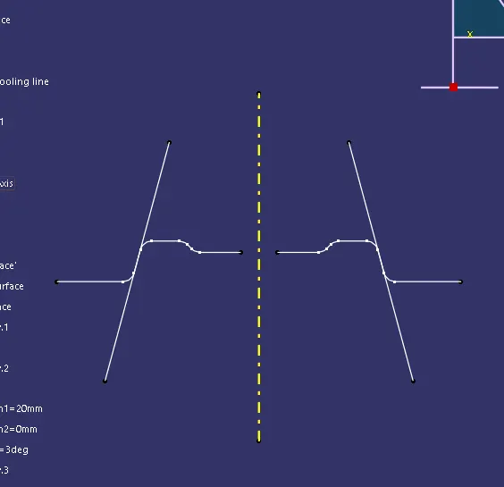
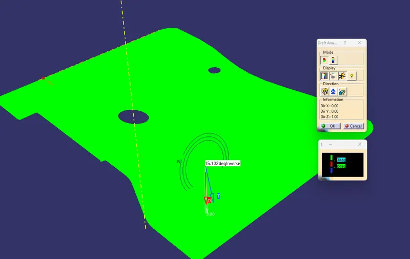
- once finalized on the toolng axis and tooling direction go on to draft analysis section. move the compass on to the tolling line and aliing it to the tooling draw direaction and perfom by clicking on the class A surface. we can update the draft values unde the colour Scale to get overall view of the surface or use analyze undet the running pint optin to see who much draft is applied on the surface at any given point.
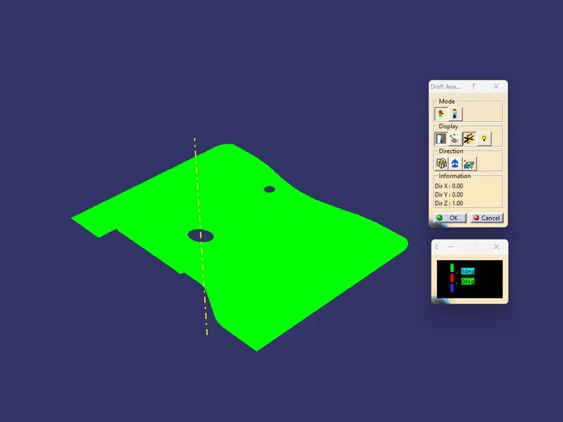
Creating Class B Surface from class A Surface:
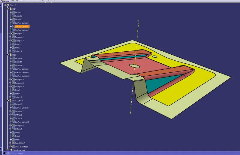
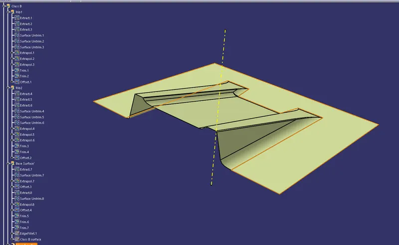
The Class B surface is the surface of the component that decides the thickenss od the component and is an offset of the high defenition class A surface. Typcally class B surface is obtained by offsetting the class A surfcae but care should be taken that the overall thickness remians the same throgh out the component.
The following tree strcutres shows the steps that are included in creating the Bsurface.
Creating Class C Surface:
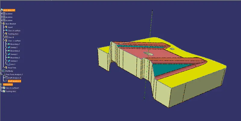
Class C surface is the closing surface that joins the class A surface to the Class B surface. while creating this surface we have to consider the draft to be applied on this surfce as well.
The below tree strcuter shows the steps used for creating the Class C surface here
Creating a solid body using close surface command:
The Final trim or the closed volume for the is obtinaed by combining all the 3 surfcaes.
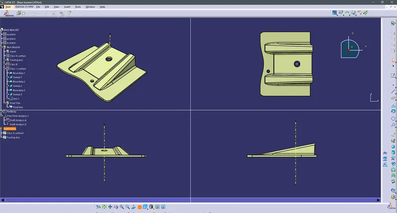
The solid componet is obtined by thickening the closed volume.
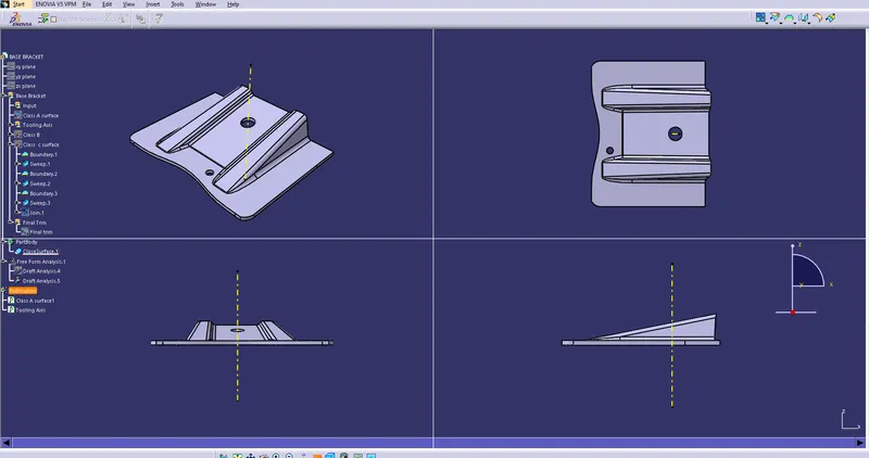
performing a draft analysis for the final model:
A Similar analysis method is used as we have perfomed for the Class A surface.we will use the tooling direction and axis to detremine the overall draft on the final component.