Week 9 - Challenge 2 - Switch Bezel Design
DESIGN AND DRAFT ANALYSIS OF SWITCH BAZEL
Aim: This project aims to create a Switch Bezel plastic component using the given class asurface following the OEM standard and Draft Analysis.
Class A- Surface
- First, the given styling surface is checked for any irregularities and if found any then it is corrected by using Trim, Extrapolate, Split and Join commands.
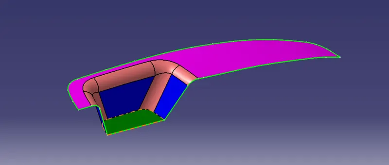
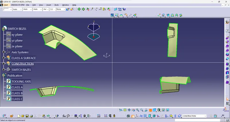
- The below image shows that the Class – A surface is clean and no irregularities present, so let's move on to the next step.
Objective :
- Ensure Proper tree Structure.
- Geometrical sets should have a proper name based on the sketche present inside tree
- All the sketches should be created under the geometrical set.
- Use the Close surface feature to make a solid body from the surface.
- To publish the tooling Axis, Class A, B, and C surface.
Software :
- CATIA V5 (Generative Shape Design)
INTRODUCTION :
CLASS-A SURFACE : The class a surface used in the automotive design industry . it describes the final production data for aesthetics parts.
CLASS- B SURFACE: The class B surface is the second surface that has a certain thick from the class-B surface. this surface curttains engineering aspects of a model. These must be smooth and "error-free aas well but are not held to the standards that class surfaces are.
CLASS- C SURFACE:The Draft analysis should also pass for Class - C surfaces.
- Tooling direction construction:
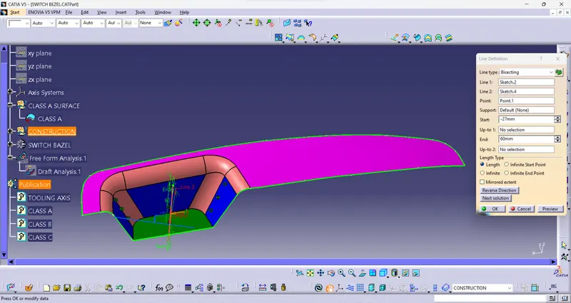
Ejection from the cavity of the mould after producing the inside trim (switch bezel) must have the nominal 3-degree Draft angle. As a result, the tooling direction is determined by taking all of the above into account, and the bisecting method is employed.The class - A's base surface was removed, and a point in the centre was produced, and an axis system was attached to the point with the present feature disabled.
Then, using the project intersection along the yz plane, the two inclined lines were drawn inside the drawing.Then, using the two inclined lines, bisecting lines were created.
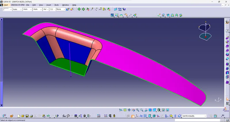
The same technique is followed along the xz plane, but because one side lacks inclined lines, the centre point is utilised to extrude a line down the z-direction, yielding a measurement of 5 degrees.The bisecting line is created and published as Tooling Axis (tooling direction) using these two lines from sketches 1 and 2.
Class - B surface creation:
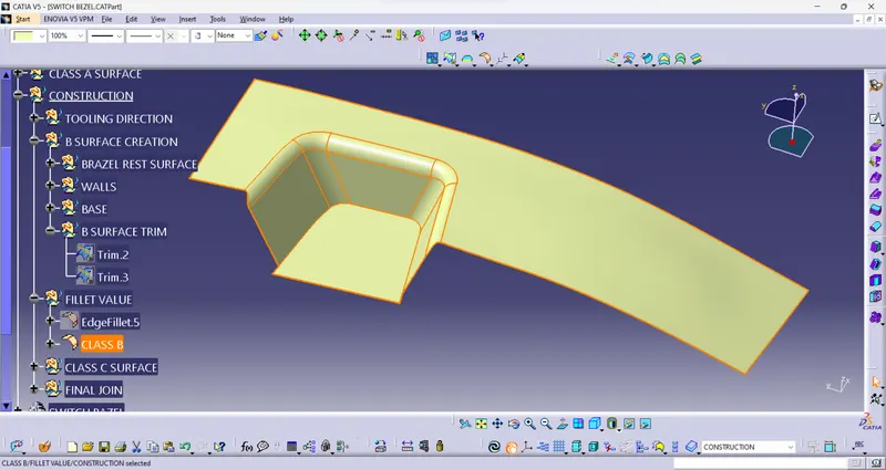
To create the class-B surface, the needed surface was excised, except for the offset surface, and then the whole surface was untrimmed.
Then, all of the surfaces were extrapolated to find intersections.
Because the Switch bezel is 2.5mm thick, the B-Surface was offset to 2.5mm and the necessary trim operations were performed.
- Class - C surface creation:
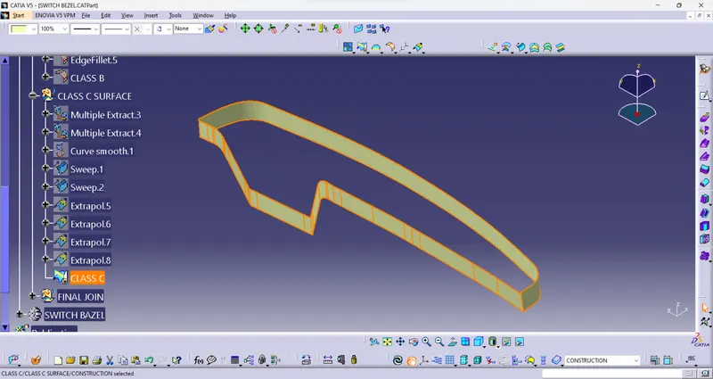
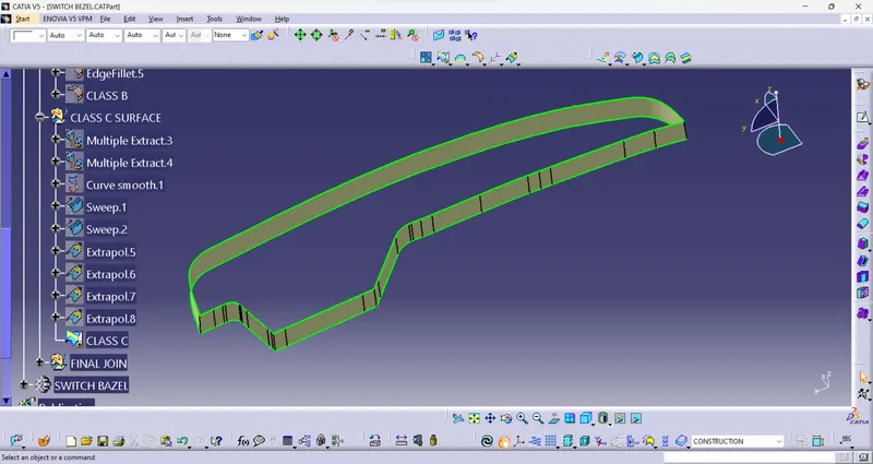
Multiple Extract was used to extract the requisite outside margins of the A-Surface. The curve is then smoothed using the Curve Smooth option to prevent the spots.
The surface was then constructed using the sweep command, using the following feature controls,
Profile type – Line
Subtype – With Draft Direction
Guide Curve – Smooth Curve
Draft Direction – Tooling Axis
Draft Computation Mode – Square
Angle – 3 Degree
Angle Sector – Positive Downward (1)
Length – 20mmThe edges were then crossed between the surface corners using the extrapolation command, making trimming easier.
The required section of the C - surface was now removed.
Steps:
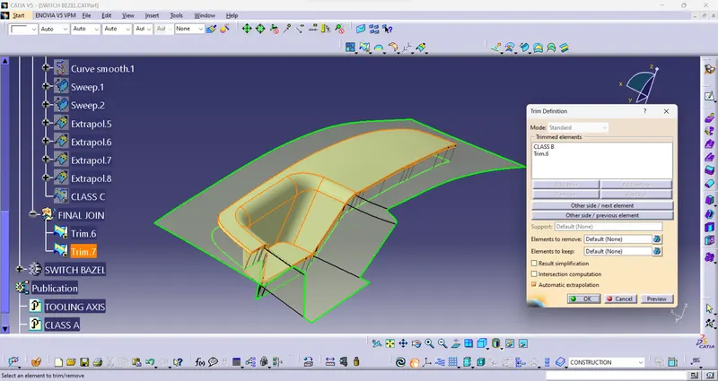
- Creating a closed surface:
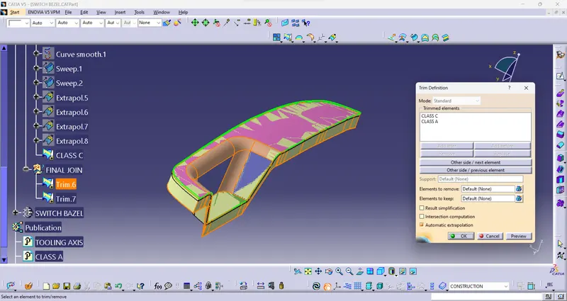
The class A and class C surfaces were now linked by reducing the gaps between them using extrapolation (tangent continuity) and Trim surface.
The Switch bezel's precise surface was then cut from the above-resulted trim surface using the class-B surface.
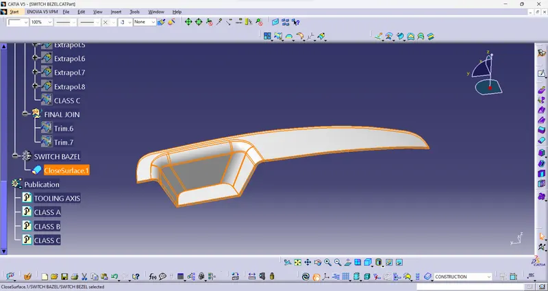
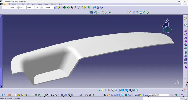
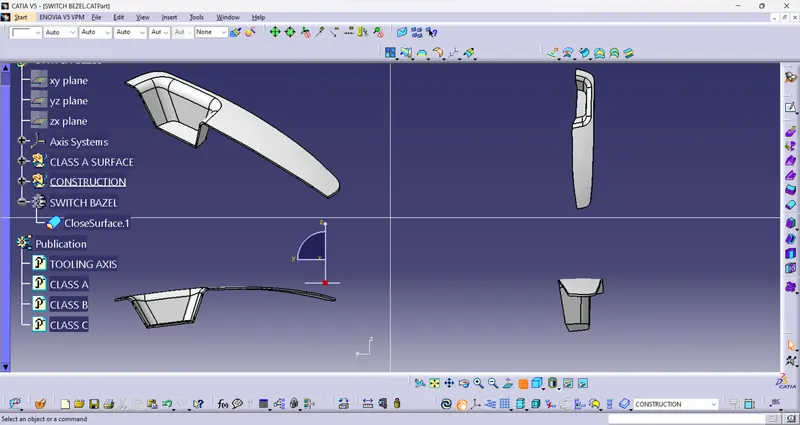
- The Draft analysis process:
Before producing the Class -B&C surface, the Class -A surface must be examined, and then the solid body must be assessed. Both may be accomplished by following the steps outlined below.
When the view mode is changed to custom view parameters - Material mode, the feature Draft analysis is enabled.
The compass was then triggered and aligned with the tooling axis by sliding the red pointer, which was then locked.
The nominal value will then be 3 degrees and tested for the component's Draft angle by selecting the quick analysis method.
The green color region indicates that it meets the 3-degree Draft angle requirement. If not satisfactory, the area is measured with the Running point tool and then adjusted to provide a successful Draft for the generated tooling direction.