Week 10 - Challenge 1- Attachment Feature Creation (Ribs & Screw Boss)
Attachment Feature Creation (Ribs & Screw Boss) - Challenge 1
AIM
Create the rib for the Drill Handle considering the design rules.
INTRODUCTION
Ribs and screw bosses are engineering features which are created on the B side of the plastic components.
RIBS
Ribs are used to strengthen the walls of your mould without increasing wall thickness which means that you minimise the problems that come into play when the wall thicknesses have to be increased.
In essence, if the wall is too thick, warping and sinking can result so that the entire design may need to be rejected.
SCREW BOSS
Boss features are commonly found in injection molding designs. They are used to aid in the assembly of molded parts by providing a channel for a screw. Designing plastic screw bosses is fairly straightforward but there are a few considerations to ensure a strong connection between parts and mitigate cosmetic defects.
OBJECTIVE
- Create Tooling axis for the given CLASS -A surface.
- Create the CLASS B and C surfaces of drill handle using the given CLASS-A surface.
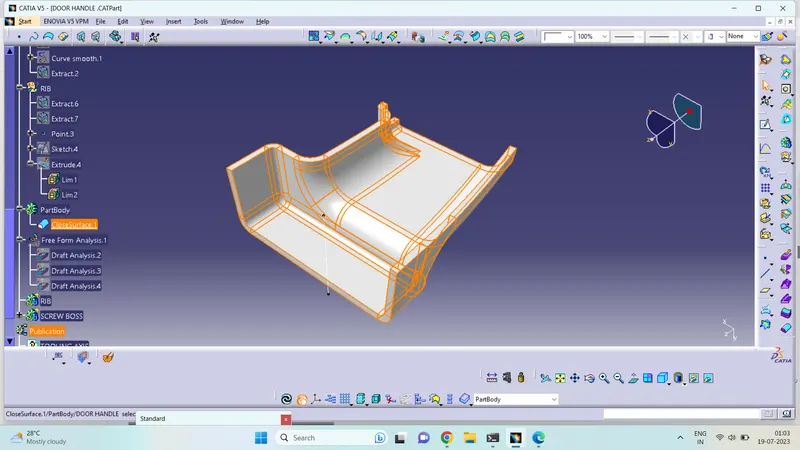
- Create final surface model and convert it into solid body using close surface command in the part design workbench.
- Create ribs and screw bosses on the B surface by considering the design rules.
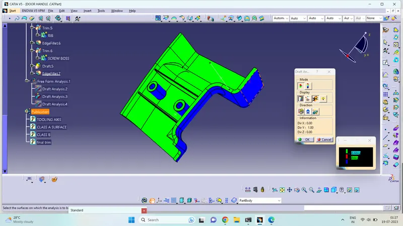
- Perform draft analysis for both Class-A surface and Final part body.
Design methodology
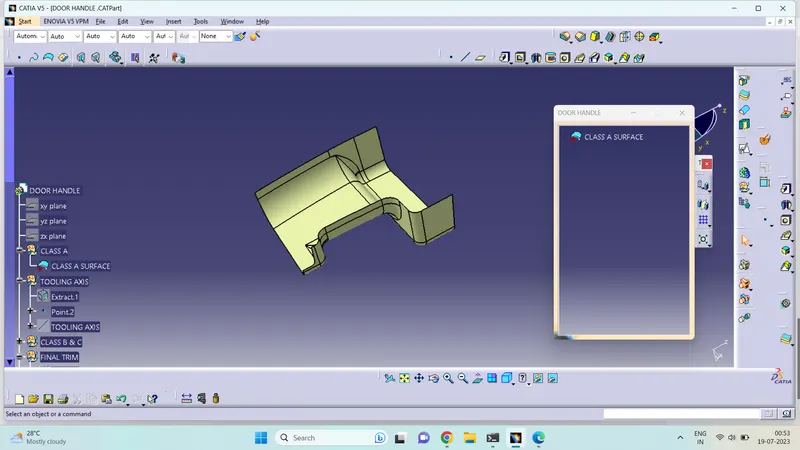
Class-A surface means visible surface. It gives the aesthetic of the component which is created by the styling team and gives to the part design engineer to create the part with all engineering aspects.
Given CLASS-A surface
Tooling axis creation
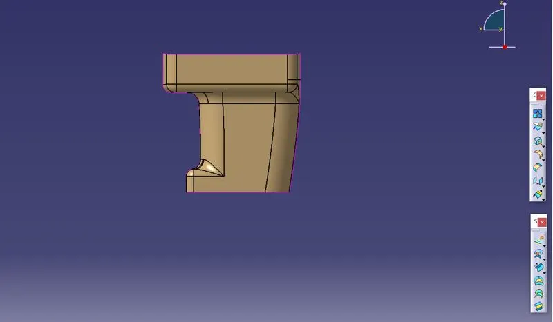
- Arrange the view manually to check the best tooling direction which covers most of the surfaces.
- Tooling direction along Y axis can clear most of the surfaces. So we can create tooling axis along y direction.
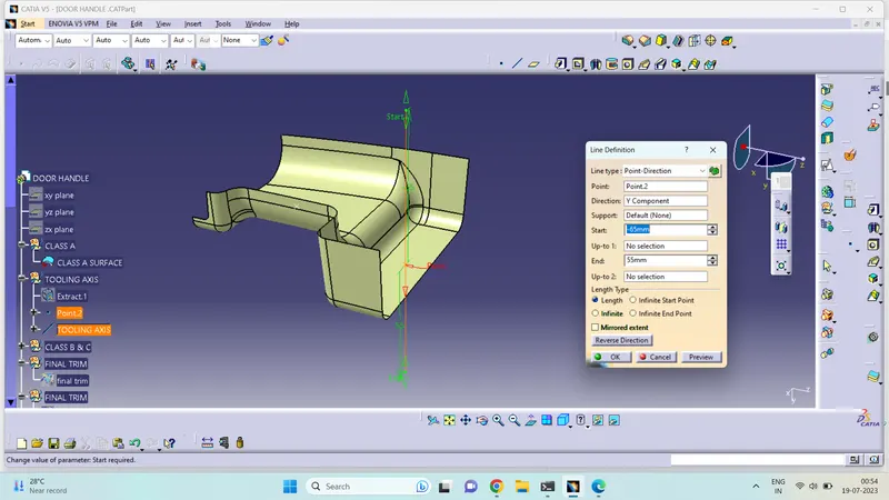
- I have created tooling axis using normal to the surface method. For that extract a plane surface and create a midpoint on it.
- Create a line on the point and direction along y axis.
CLASS-B surface creation
Class-B surface means thickness of a part it is not visible and is inside part. In other words, Class-B surface is a surface below a certain thickness from the class-A surface. This is the surface that contains engineering aspects of a model.
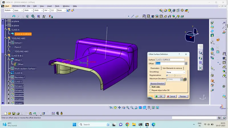
- Offset the class-A surface about 2.5mm inward direction.
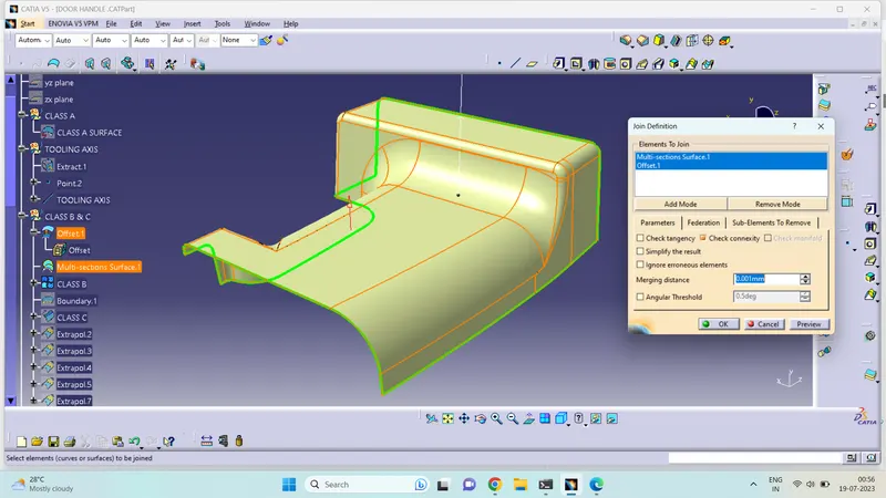
- Work on the patches created on the offset surface with the help og extracted curves and multi section surface features.
- We can join the working surface and check for the continuity.
CLASS-C surface creation
Surface that joins class-A and class-B surfaces is class-C surface. Class C is often specified for interior surfaces not readily visible, surfaces that will be covered by another part when assembled
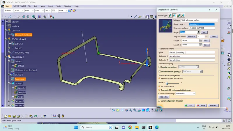
- Multi extract the boundary edges and sweep it with reference to surface at 90 degrees, this method is useful when the created sweep surface is facing perpendicular to the tooling axis.
- C surface sweep which is creating parallel to the tooling axis should have at least 3 degree of angle value while sweeping to pass the draft analysis.
- Create curves using extract feature and connect curve features to create sweep surface on the complicated regions.
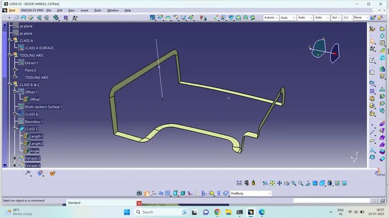
- Extrapolate the sweep surface at required edges and trim it with the other surface.
- Then join the whole sweep surfaces created and check for the boundary.
Creating Final Drill handle surface
- Join the CLASS-A surface with CLASS-C surface.
- Extrapolate the CLASS-B surface and trim it with Joined surface.
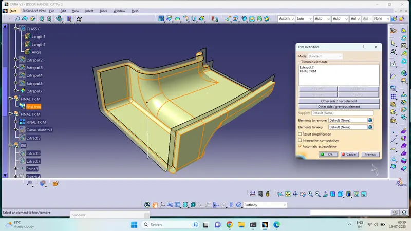
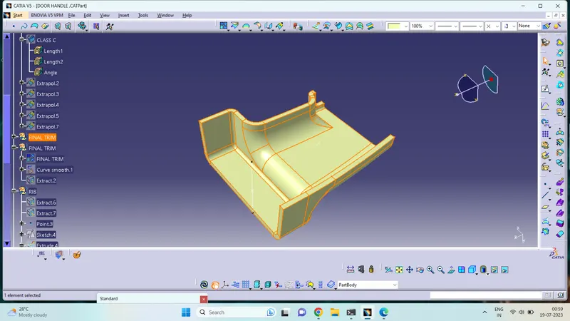
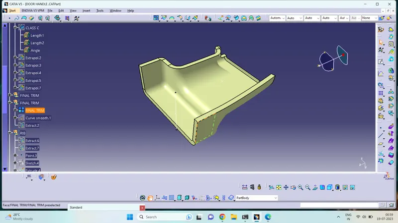
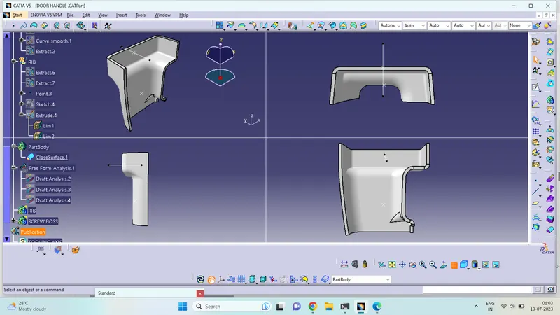
Then create the solid part using close surface command in the part design workbench.
 \
\
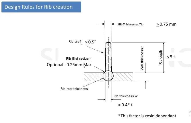
ib Creation
- Draft: 0.5 Degree per side (minimum)
- Thickness of ribs: 40% of wall thickness
- Height: ≤ 5 times the wall thickness
- Spacing (for more than 1 rib): 3:1- steel height/width ratio (maximum). h/w =3 or2(preferred) where h is the height of the rib and w is the space between two ribs.
- Minimum thickness at the tip: 0.75
- Radius: 0.25mm max
- Rib root thickness should not be more than 30% of the wall thickness.
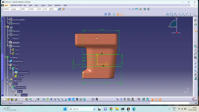
- Create positioned sketch for the ribs and extrude the sketch with reference to the tooling axis or other method is create thicken pad with reference to the tooling axis.
- Perform union of ribs with the drill handle part body
 \
\
Screw Boss creation
- W= 0.6*T
- Draft 0.5 Degree on both inside and outside walls of the screw boss.
- Height to diameter ratio – 3:1
- Radii(fillet) – 0.25mm(maximum)
- Boss Gussets must meet rib guidelines
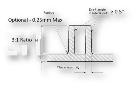
- Create sketch of screw boss and extrude it with reference to the tooling axis.
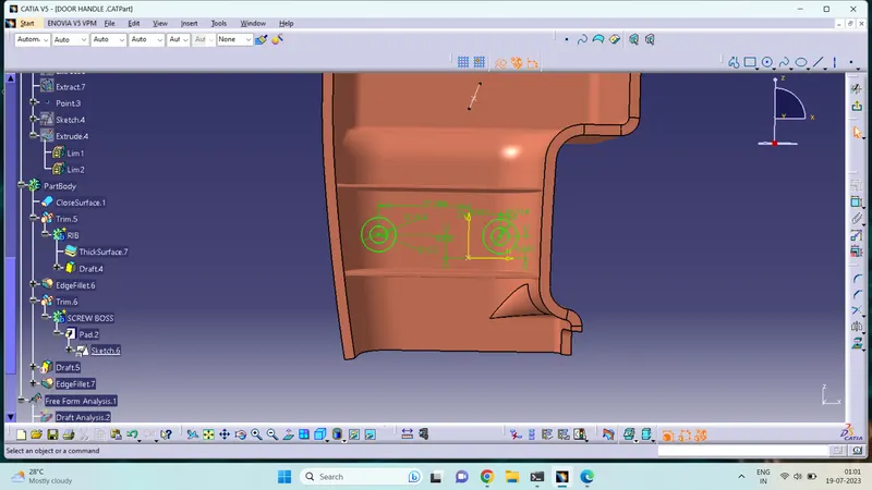
Final part after creating ribs and screw bosses on the b side of the component
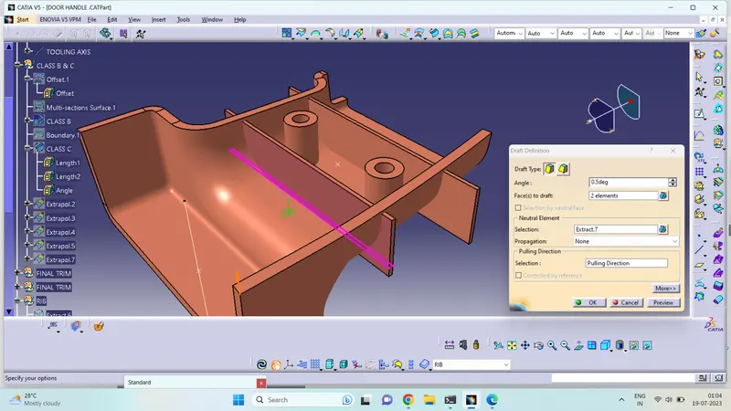
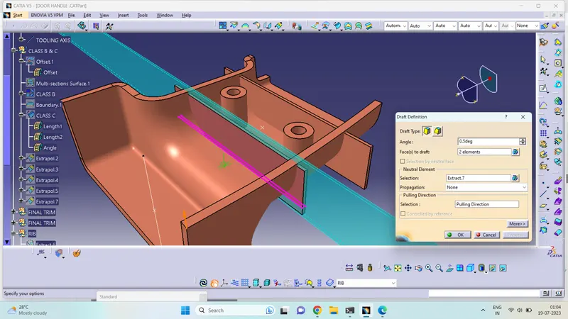
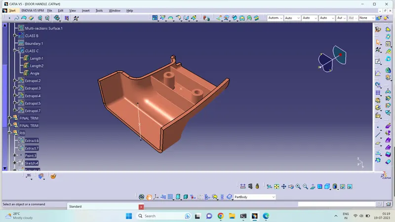
Rib root thickness Analysis
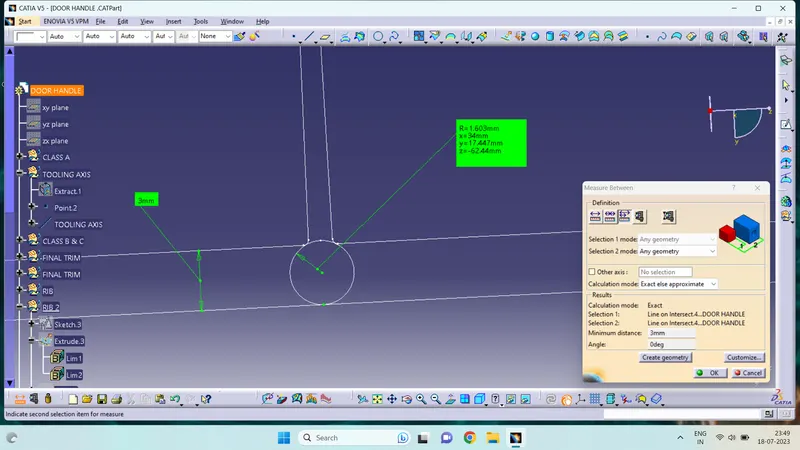
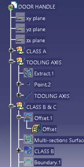
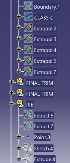
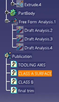
The expanded Tree Structure for the geometrical set and the Part Body
Draft analysis of surface A
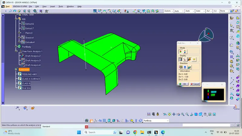
Draft analysis of solid part