Week 9 - Challenge 2 - Switch Bezel Design
Creating the close body and performing the draft analysis onto it.
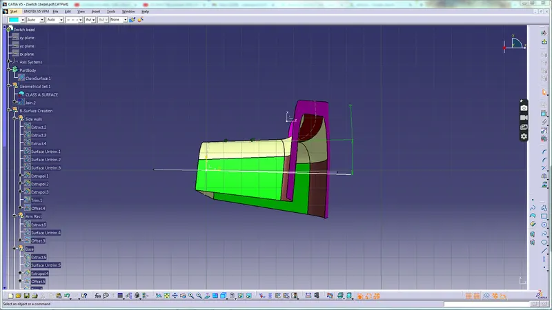
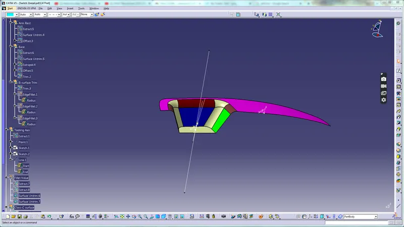
Creation of Tooling Axis:
- Exract the Base surface.
- Create a point o the surface.
- The next step is to create an axis system on the surface with the created point as the origin.
- Create a new positioned sketch with axis system and Base surface and take the intersection of Class A surface with the point.
- Draw two lines on two surfaces of the intersection.Then create a bisecting line for these lines and put the rest lines in construction mode leaving only the bisecting line.This is the tooling axis for the Y-direction.
- Similiarly create a tooling axis for the X-direction (by creating the new sketh,intersecting it,then creating a line at an angle of 3 degree from the top surface .)
- Now bisect these two lines that we got(tooling axis for y and x direction) with the point on the surface as refernce point.This line is the final tooling axis that we require.
- Change the colour and the thickness of this tooling axis as you want.
Creation Of B-surface:
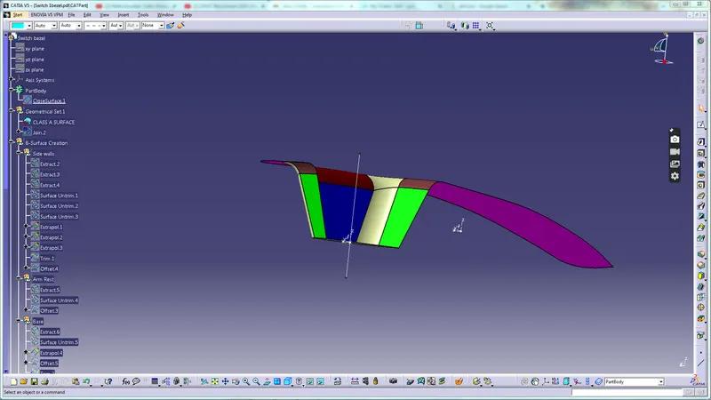
- Insert a new Geometrical set as B-surface creation.
- Create a new geometrical set namely Arm rest under this geometrical set.Extract the top surface then untrim it.
- Similiarly create a new gemoetrical inside B-surface name it as Side walls.Extract the side walls without touching the fillets.Then untrim it one by one.
- Unhide the top surface.Extrapolate these side walls and the top surface(with curvature continuity and propogation type as point continuity )so that they can meet each other.
- Trim all the three walls.
- Extract the Base ,untrim it and insert in new geometrical set.Then Extrapolate it.
- Offest the walls,the arm rest and the base to 3mm (thickness of the component) along proper direction.
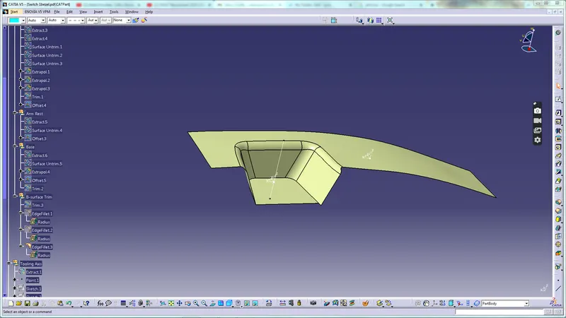
- Trim these surfaces to get the final result.
- Extract the fillet surface of class A and measure the fillet value .
- Give this fillet value to the final trims we got(Fillet value- wall thickness i.e 15-3 and 14 -3).This is our Class-B surface
Creating C surface:
- Insert a new geometrical set as Class-C surface.
- Extract the boundaries of the top surace and front surface of Class A by using the multi extract command.
- Use smooth curve to smooth the curve and avoid further errors.
- Sweep the top curve with draft direction as tooling axis.Give the draft of 3 degree with outside direction.
- Similiarly sweep the front face with 3 degree draft and outside direction.
- Extrapolate both the sweeps and trim them.
- Join the class A and class C with meging distance or trim class A and Class C.
- Finally trim it Class B surface.
- Select the boundary .If the boundary does not form theoutput is correct.
- Create a close body in part workbench.
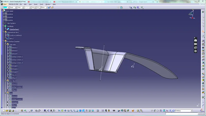
Performing the Draft anaylsis:
- Switch to material mode first.
- Select draft analysis.Click on compass.Move and align the compass onto the tooling axis.Apply the lock symbol.
- Click on red colour crosson surface.Change the colours as >3 degree in green colour,0-3 degree in blue colour and red is negative.Turn the light option off.
- Click on analysis under the running point .
- When we moved this option to diffrent edges we found out that most of the edge have 3 degree draft and appeared to be green and some surfaces have 2.97 to 2.99 degree draft .So they appeared blue in colour.
- So to clear the error we have changed the value of the draft analysis from 3 degrees to 2.9 degree.
- Other surfaces appeared to be red and blue whos draft andle were less than 0 and 3 resp.
- This is how we have performed the draft analysis on the body.