Week 9 - Challenge 2 - Switch Bezel Design
OBJECTIVE:
Create the Switch Bezel Plastic component through the given Class-A surface
GIVEN CLASS A SURFACE:
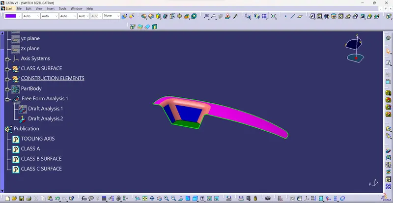
It is a car part which contains switches and buttons to control different functions like window control,door lock,media etc. It is located at the inner portion of the door
PROCEDURE TO FOLLOW:
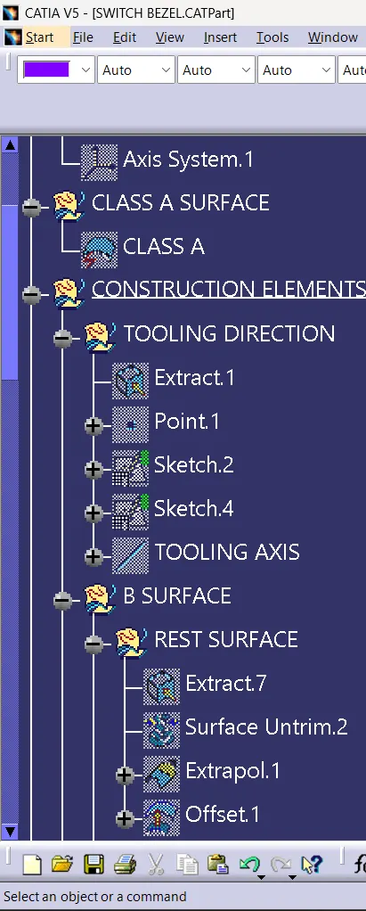
- Tooling axis creation
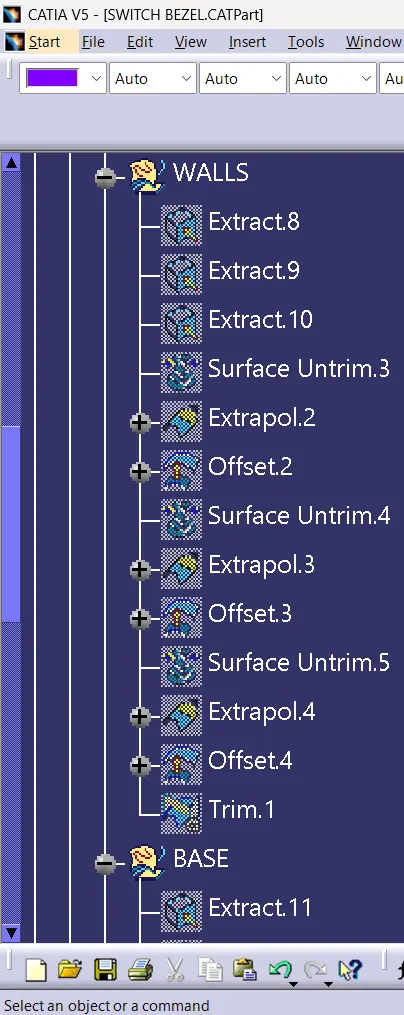
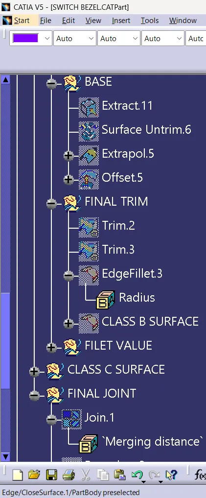
- Creation of CLASS B surface
- Creation of CLASS C surface
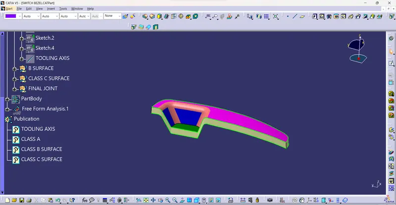
- Creation of solid body
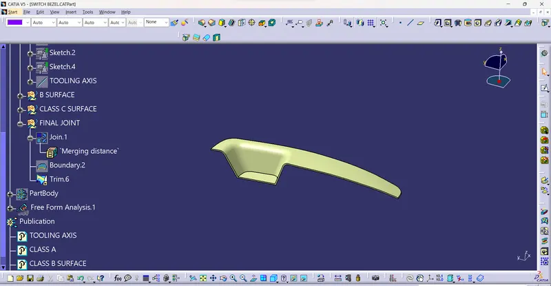
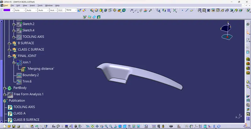
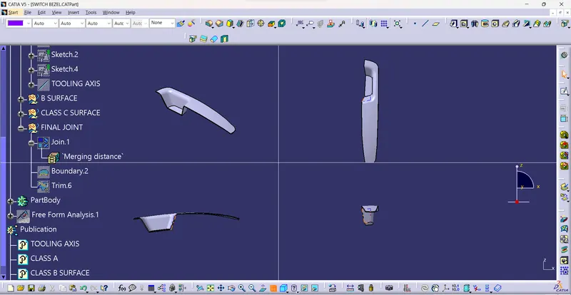
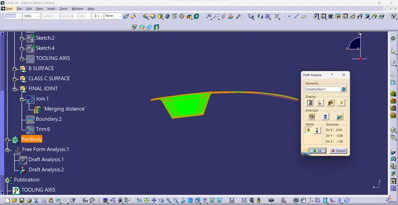
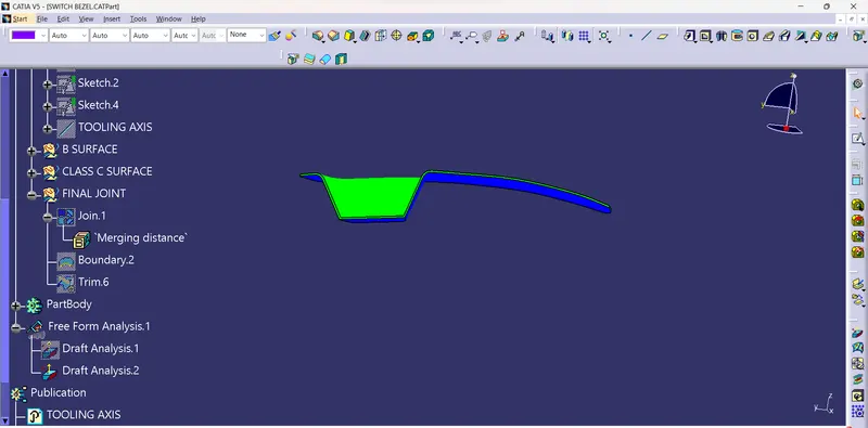
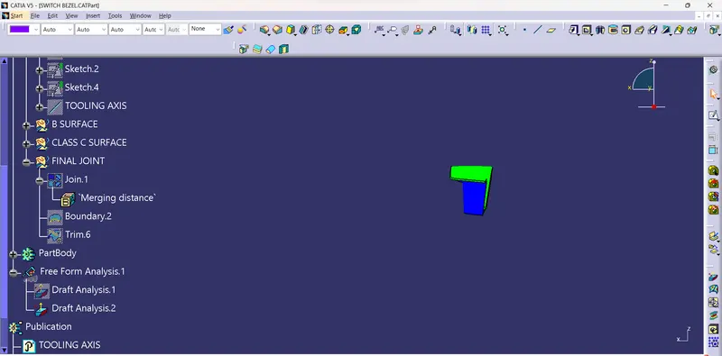
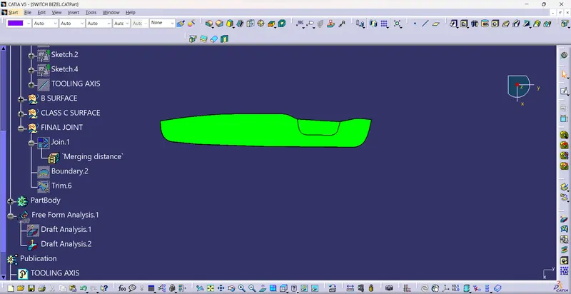
- Draft analysis of CLASS A surface and solid body
TOOLING AXIS CREATION:
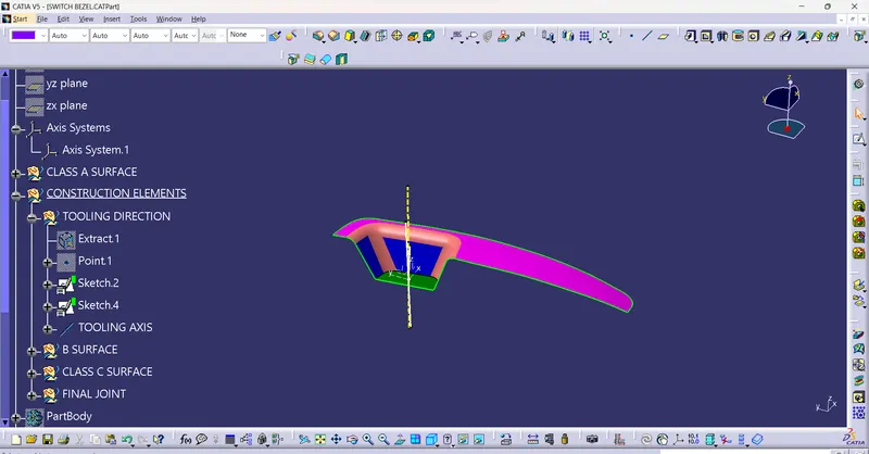
Tooling axis is the direction in which mold or core and cavity opens. The ejection of the part from mold depends on the draft. A zero draft can result in difficult or no ejection due to shrinkage.
- Using join and boundary command check the CLASS A surface.
- Then the dip area which is along the z direction is taken in to account,a point is created at the centre of the base surface and an axis system created there.
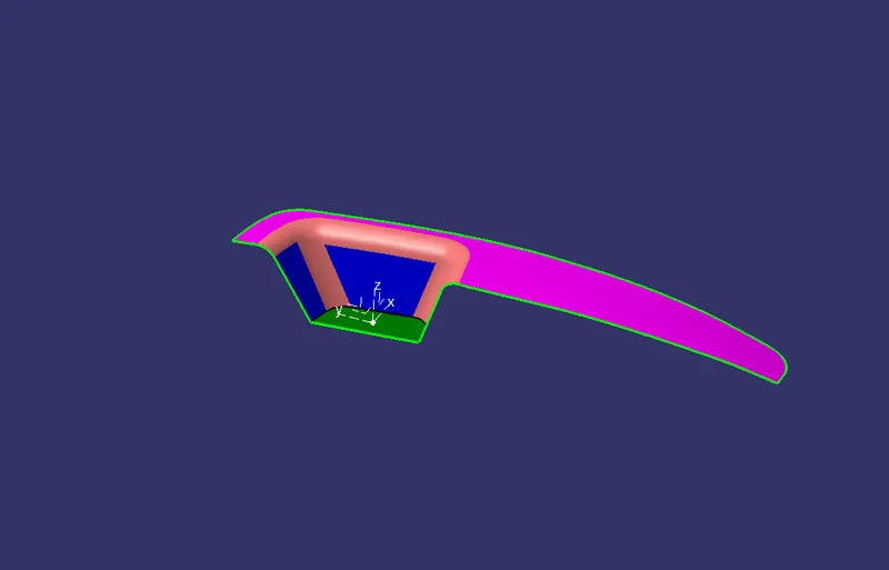
- Then an inter section is made usng CLASS A surface and zy plane.using the inter section curve two lines are draw along the curve direction and using that line a bisecting line is created.
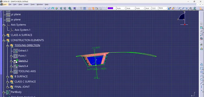
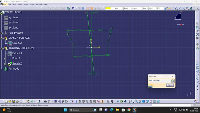
- Same way an inter section is created at the zx plane with class A surface.here there is only one side to draw line, so a line is draw from the centre at an angle 6 degree which is consider a dummy axis.
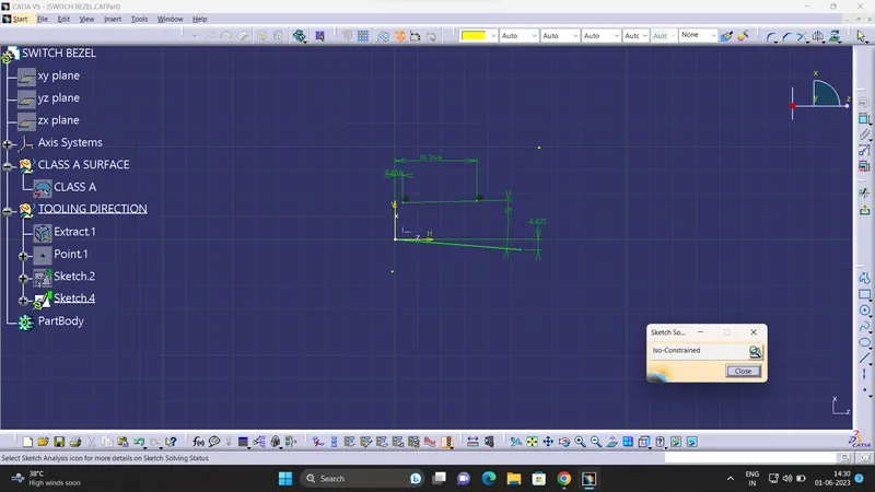
- By using these two lines an bisecting line is created which is the main tooling axis.
DRAFT ANALYSIS :
The draft angle is the amount of taper perpendicular to the parting line for molded or cast parts. It is measurable in degrees. Because plastic shrinks and sticks on molding surfaces as it cools, we draft the walls of the plastic part so that it ejects or breaks free from the molding surfaces more easily and without dragging. To reduce the risk of damage to the elements and ensure ejection, a functional injection molding part must have drafts on both the cavity and core sides.
ADVANTAGES:
- Reduces the possibility of part damage due to friction during the release
- Ensures a uniform, smooth, unscratched finish
- Reduces overall cooling time by reducing or eliminating the need for unusual ejection setups
- Reduces mold wear and tear
PROCEDURE IN DRAFT ANALYSIS :
- First change the created part into material.
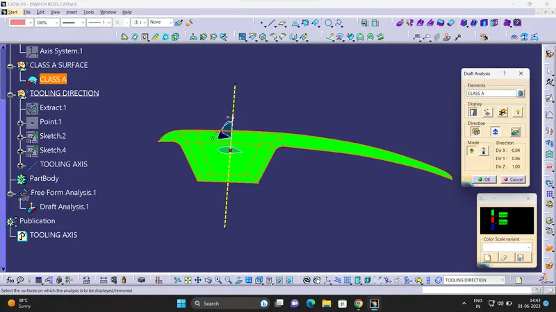
- Click on the compas and plase in the tooling direction.
- Use the lock command to fix the compass
- Click on the surface and apply the draft angle(minimum draft angle is 3 degree)
CLASS B SURFACE:
CLASS B surface is created by offseting the CLASS A at 2.5mm.
CLASS C SURFACE:
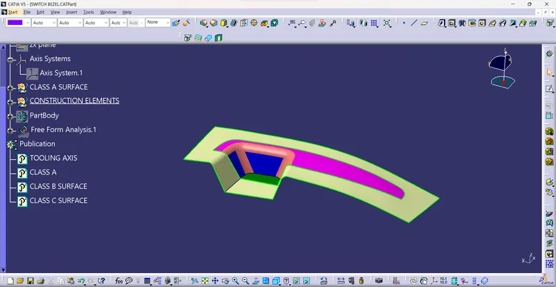
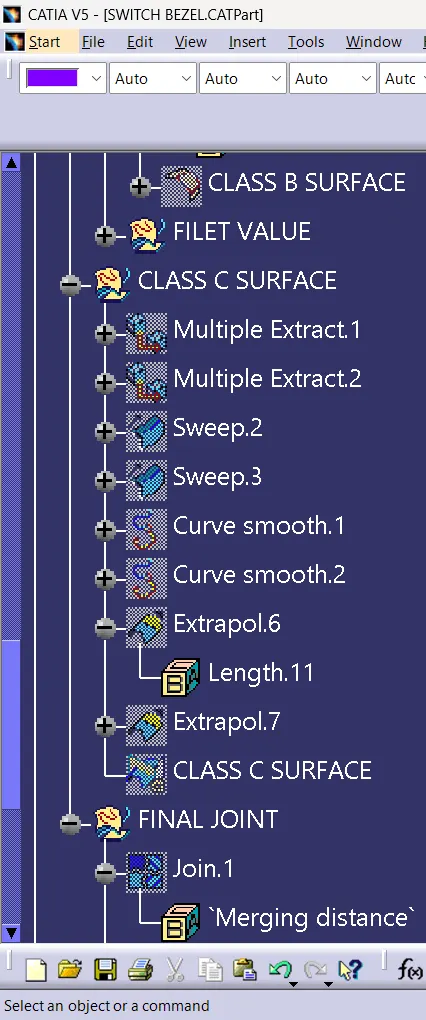
- To create the class C surface, I extracted the boundary of the class A surface by using the multiple extract command.
- Now extended the class A surface boundary by using sweep command with 3 deg of draft angle.
- The surface was having too many marks so smooth curve command selected and replaced by the the above curve to obtain a smooth surface without marks.
- Surface A and C were joined by giving 0.003mm as merging distance.
CREATION OF SOLID BODY:
- DRAFT ANALYSIS
2.9 degree is given to the draft angle.
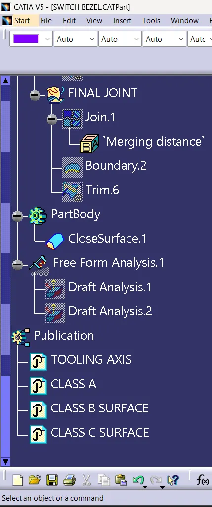
CONSTRUCTION TREE STRUCTURE:
PART TREE STRUCTURE:
CONCLUSION :
Switch Bezel Plastic component is created through the given Class-A surface .