Week 9 - Challenge 2 - Switch Bezel Design
OBJECTIVE
Creating a Switch Bezel Plastic component through the given Class-A surface.
INTRODUCTION
The control panel bezel serves as the frame for the window switch, holding the switch covers and buttons securely in place. Considering the manufacturing process used by most OEMs, which involves plastic molding for automotive trims, the design of the switch bezel takes into account these manufacturing considerations.
DESIGN CONSIDERATION
- The Class-A surface should exhibit a high level of aesthetic smoothness and quality in its appearance.
- The Class-B surface should include all necessary supporting features, such as ribs, to ensure structural integrity and functionality.
- The parting line should be aligned with the Class-B surface to prevent any impact on the aesthetic quality of the Class-A surface due to flashing.
- The Class-C surface should also meet the requirements of draft analysis, ensuring proper draft angles for ease of molding and manufacturing.
PERFORMING DRAFT ANALYSIS
- The first step in the process is to check the Class-A surface for quality and smoothness before creating the Class-B and Class-C surfaces. This can be done by changing the view mode to custom view parameters - Material mode, which enables the feature draft analysis.
- Next, the compass tool is activated and aligned with the tooling axis by dragging the red pointer and locking it in place. The quick analysis mode is then selected, with a nominal value of 3 degrees, to check the component's draft angle.
- The green-colored area indicates that the 3-degree draft angle requirement is satisfied. If it does not meet the requirement, the Running point tool can be used to measure the area and make necessary alterations to achieve a successful draft for the created tooling direction.
STEPS FOR CREATING TOOLING AXIS
-
Extract the base surface: I began by extracting the base surface of the Class-A mold. This surface served as the foundation for creating the tooling direction.
-
Create a central point and axis: Within the base surface, I created a central point to represent the midpoint of the switch bezel. Then, I inserted an axis system at this point, ensuring that the current feature was disabled to prevent unintended changes.
-
Sketch inclined lines: Using the project intersection method along the yz plane, I created two inclined lines within the positioned sketch. These lines were drawn to match the desired 3-degree draft angle.
-
Draw bisecting lines: Next, I drew bisecting lines that intersected with the inclined lines from the previous step. These bisecting lines played a crucial role in determining the final tooling direction.
-
Repeat for the xz plane: I repeated the same procedure along the xz plane. Since inclined lines were not available on one side, I used the central point to extrude a line along the z-direction. This line was given a tentative measurement of 5 degrees.
-
Create the tooling axis: By combining the lines from both the yz and xz planes, I created a bisecting line that represented the tooling axis. This line was positioned based on the intersection points of the previous lines.
-
Publish as tooling direction: Finally, I published the created bisecting line as the tooling direction for manufacturing the interior trim. This ensured that the ejection from the mold cavity aligned with the desired 3-degree draft angle.
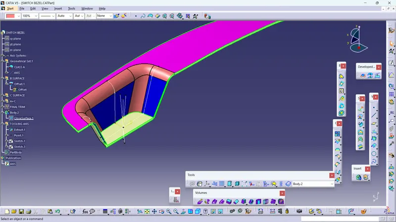
CREATING B SURFACE
B SURFACE -The Class-B surface is the secondary surface that is created with a certain thickness from the Class-A surface. It serves to incorporate the engineering aspects of the model. While the Class-B surface also needs to be smooth and free from errors, it is not required to meet the same stringent standards as Class-A surfaces.
The B surface is created using the offset method. I directly applied the offset command to the given A surface, setting the offset distance to 2.5mm as required.
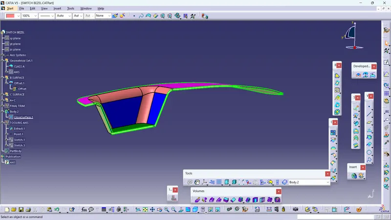
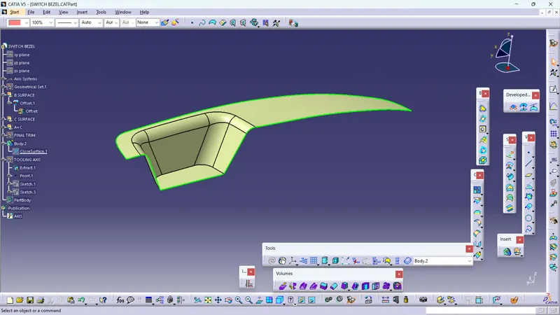
CREATING C SURFACE
C SURFACE -Class C is commonly specified for interior surfaces that are not readily visible, surfaces that will be covered by another part when assembled, or surfaces where visual perfection is not a critical requirement. This classification acknowledges that these surfaces may have slight flaws or imperfections that do not impact the overall functionality or aesthetics of the final product.
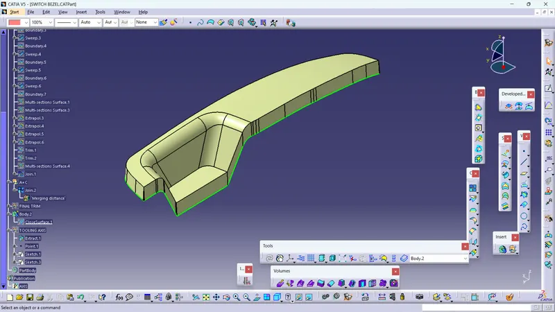
The Class C Surface is created using the Sweep command and by giving positive draft direction with the tooling axis for the 3 degrees. that is required to maintain the efficacy of the operation to manufacture a part.
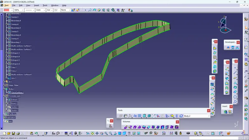
JOINING A + C SURFACE
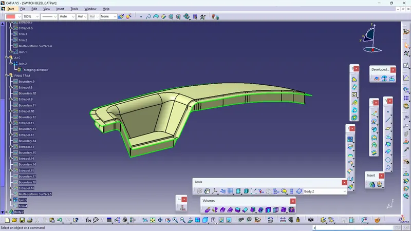
JOINING A+B+C SURFACE
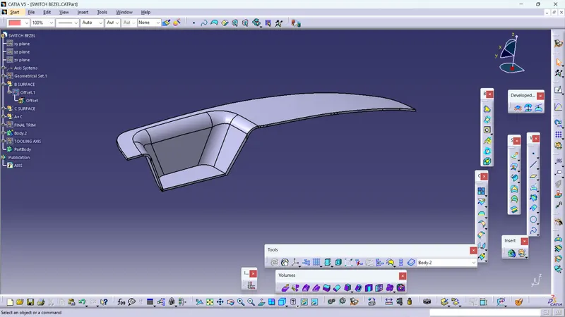
FINAL DRAFT
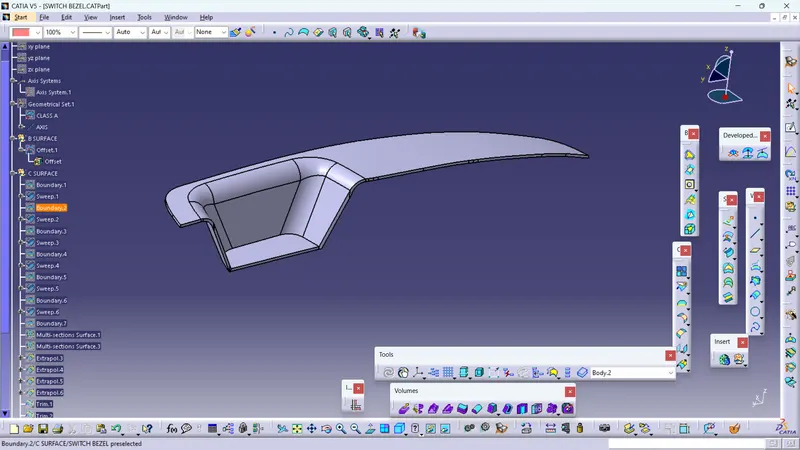
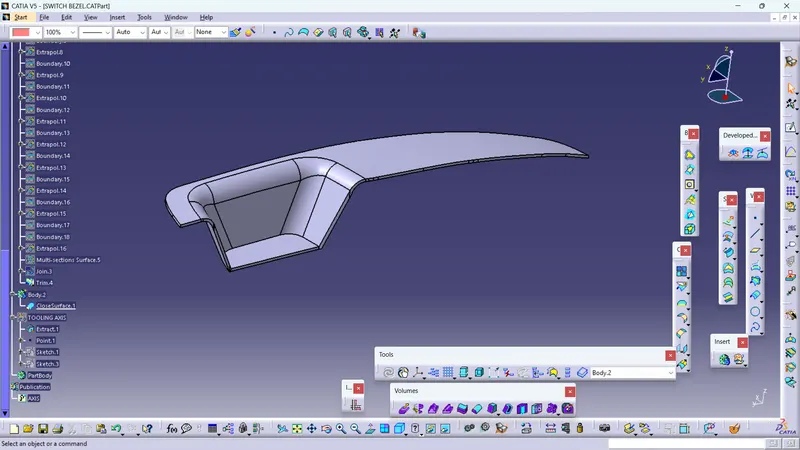
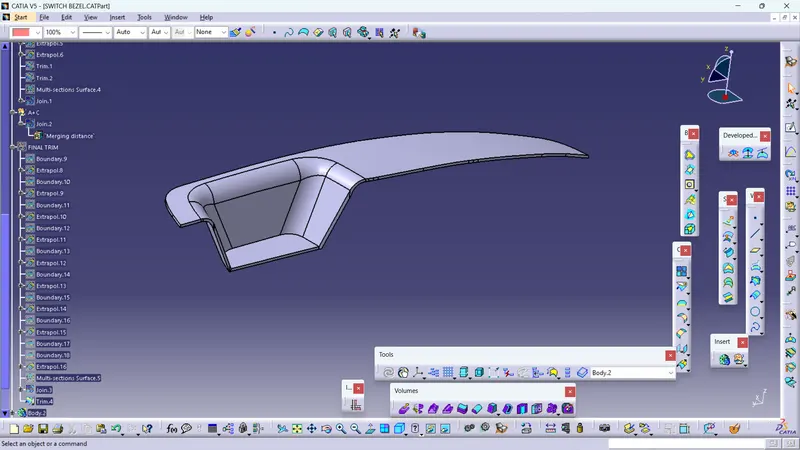
TREE STRUCTURE
CONCLUSION
The switch bezel component is created using the Class-A surface, ensuring that it aligns with the draft analysis requirements.
OBJECTIVE
Creating a Switch Bezel Plastic component through the given Class-A surface.
INTRODUCTION
The control panel bezel serves as the frame for the window switch, holding the switch covers and buttons securely in place. Considering the manufacturing process used by most OEMs, which involves plastic molding for automotive trims, the design of the switch bezel takes into account these manufacturing considerations.
DESIGN CONSIDERATION
- The Class-A surface should exhibit a high level of aesthetic smoothness and quality in its appearance.
- The Class-B surface should include all necessary supporting features, such as ribs, to ensure structural integrity and functionality.
- The parting line should be aligned with the Class-B surface to prevent any impact on the aesthetic quality of the Class-A surface due to flashing.
- The Class-C surface should also meet the requirements of draft analysis, ensuring proper draft angles for ease of molding and manufacturing.
PERFORMING DRAFT ANALYSIS
- The first step in the process is to check the Class-A surface for quality and smoothness before creating the Class-B and Class-C surfaces. This can be done by changing the view mode to custom view parameters - Material mode, which enables the feature draft analysis.
- Next, the compass tool is activated and aligned with the tooling axis by dragging the red pointer and locking it in place. The quick analysis mode is then selected, with a nominal value of 3 degrees, to check the component's draft angle.
- The green-colored area indicates that the 3-degree draft angle requirement is satisfied. If it does not meet the requirement, the Running point tool can be used to measure the area and make necessary alterations to achieve a successful draft for the created tooling direction.
STEPS FOR CREATING TOOLING AXIS
-
Extract the base surface: I began by extracting the base surface of the Class-A mold. This surface served as the foundation for creating the tooling direction.
-
Create a central point and axis: Within the base surface, I created a central point to represent the midpoint of the switch bezel. Then, I inserted an axis system at this point, ensuring that the current feature was disabled to prevent unintended changes.
-
Sketch inclined lines: Using the project intersection method along the yz plane, I created two inclined lines within the positioned sketch. These lines were drawn to match the desired 3-degree draft angle.
-
Draw bisecting lines: Next, I drew bisecting lines that intersected with the inclined lines from the previous step. These bisecting lines played a crucial role in determining the final tooling direction.
-
Repeat for the xz plane: I repeated the same procedure along the xz plane. Since inclined lines were not available on one side, I used the central point to extrude a line along the z-direction. This line was given a tentative measurement of 5 degrees.
-
Create the tooling axis: By combining the lines from both the yz and xz planes, I created a bisecting line that represented the tooling axis. This line was positioned based on the intersection points of the previous lines.
-
Publish as tooling direction: Finally, I published the created bisecting line as the tooling direction for manufacturing the interior trim. This ensured that the ejection from the mold cavity aligned with the desired 3-degree draft angle.
CREATING B SURFACE
B SURFACE -The Class-B surface is the secondary surface that is created with a certain thickness from the Class-A surface. It serves to incorporate the engineering aspects of the model. While the Class-B surface also needs to be smooth and free from errors, it is not required to meet the same stringent standards as Class-A surfaces.
The B surface is created using the offset method. I directly applied the offset command to the given A surface, setting the offset distance to 2.5mm as required.
CREATING C SURFACE
C SURFACE -Class C is commonly specified for interior surfaces that are not readily visible, surfaces that will be covered by another part when assembled, or surfaces where visual perfection is not a critical requirement. This classification acknowledges that these surfaces may have slight flaws or imperfections that do not impact the overall functionality or aesthetics of the final product.
The Class C Surface is created using the Sweep command and by giving positive draft direction with the tooling axis for the 3 degrees. that is required to maintain the efficacy of the operation to manufacture a part.
JOINING A + C SURFACE
JOINING A+B+C SURFACE
FINAL DRAFT
TREE STRUCTURE
CONCLUSION
The switch bezel component is created using the Class-A surface, ensuring that it aligns with the draft analysis requirements.
OBJECTIVE
Creating a Switch Bezel Plastic component through the given Class-A surface.
INTRODUCTION
The control panel bezel serves as the frame for the window switch, holding the switch covers and buttons securely in place. Considering the manufacturing process used by most OEMs, which involves plastic molding for automotive trims, the design of the switch bezel takes into account these manufacturing considerations.
DESIGN CONSIDERATION
- The Class-A surface should exhibit a high level of aesthetic smoothness and quality in its appearance.
- The Class-B surface should include all necessary supporting features, such as ribs, to ensure structural integrity and functionality.
- The parting line should be aligned with the Class-B surface to prevent any impact on the aesthetic quality of the Class-A surface due to flashing.
- The Class-C surface should also meet the requirements of draft analysis, ensuring proper draft angles for ease of molding and manufacturing.
PERFORMING DRAFT ANALYSIS
- The first step in the process is to check the Class-A surface for quality and smoothness before creating the Class-B and Class-C surfaces. This can be done by changing the view mode to custom view parameters - Material mode, which enables the feature draft analysis.
- Next, the compass tool is activated and aligned with the tooling axis by dragging the red pointer and locking it in place. The quick analysis mode is then selected, with a nominal value of 3 degrees, to check the component's draft angle.
- The green-colored area indicates that the 3-degree draft angle requirement is satisfied. If it does not meet the requirement, the Running point tool can be used to measure the area and make necessary alterations to achieve a successful draft for the created tooling direction.
STEPS FOR CREATING TOOLING AXIS
-
Extract the base surface: I began by extracting the base surface of the Class-A mold. This surface served as the foundation for creating the tooling direction.
-
Create a central point and axis: Within the base surface, I created a central point to represent the midpoint of the switch bezel. Then, I inserted an axis system at this point, ensuring that the current feature was disabled to prevent unintended changes.
-
Sketch inclined lines: Using the project intersection method along the yz plane, I created two inclined lines within the positioned sketch. These lines were drawn to match the desired 3-degree draft angle.
-
Draw bisecting lines: Next, I drew bisecting lines that intersected with the inclined lines from the previous step. These bisecting lines played a crucial role in determining the final tooling direction.
-
Repeat for the xz plane: I repeated the same procedure along the xz plane. Since inclined lines were not available on one side, I used the central point to extrude a line along the z-direction. This line was given a tentative measurement of 5 degrees.
-
Create the tooling axis: By combining the lines from both the yz and xz planes, I created a bisecting line that represented the tooling axis. This line was positioned based on the intersection points of the previous lines.
-
Publish as tooling direction: Finally, I published the created bisecting line as the tooling direction for manufacturing the interior trim. This ensured that the ejection from the mold cavity aligned with the desired 3-degree draft angle.
CREATING B SURFACE
B SURFACE -The Class-B surface is the secondary surface that is created with a certain thickness from the Class-A surface. It serves to incorporate the engineering aspects of the model. While the Class-B surface also needs to be smooth and free from errors, it is not required to meet the same stringent standards as Class-A surfaces.
The B surface is created using the offset method. I directly applied the offset command to the given A surface, setting the offset distance to 2.5mm as required.
CREATING C SURFACE
C SURFACE -Class C is commonly specified for interior surfaces that are not readily visible, surfaces that will be covered by another part when assembled, or surfaces where visual perfection is not a critical requirement. This classification acknowledges that these surfaces may have slight flaws or imperfections that do not impact the overall functionality or aesthetics of the final product.
The Class C Surface is created using the Sweep command and by giving positive draft direction with the tooling axis for the 3 degrees. that is required to maintain the efficacy of the operation to manufacture a part.
JOINING A + C SURFACE
JOINING A+B+C SURFACE
FINAL DRAFT
TREE STRUCTURE
CONCLUSION
The switch bezel component is created using the Class-A surface, ensuring that it aligns with the draft analysis requirements.
OBJECTIVE
Creating a Switch Bezel Plastic component through the given Class-A surface.
INTRODUCTION
The control panel bezel serves as the frame for the window switch, holding the switch covers and buttons securely in place. Considering the manufacturing process used by most OEMs, which involves plastic molding for automotive trims, the design of the switch bezel takes into account these manufacturing considerations.
DESIGN CONSIDERATION
- The Class-A surface should exhibit a high level of aesthetic smoothness and quality in its appearance.
- The Class-B surface should include all necessary supporting features, such as ribs, to ensure structural integrity and functionality.
- The parting line should be aligned with the Class-B surface to prevent any impact on the aesthetic quality of the Class-A surface due to flashing.
- The Class-C surface should also meet the requirements of draft analysis, ensuring proper draft angles for ease of molding and manufacturing.
PERFORMING DRAFT ANALYSIS
- The first step in the process is to check the Class-A surface for quality and smoothness before creating the Class-B and Class-C surfaces. This can be done by changing the view mode to custom view parameters - Material mode, which enables the feature draft analysis.
- Next, the compass tool is activated and aligned with the tooling axis by dragging the red pointer and locking it in place. The quick analysis mode is then selected, with a nominal value of 3 degrees, to check the component's draft angle.
- The green-colored area indicates that the 3-degree draft angle requirement is satisfied. If it does not meet the requirement, the Running point tool can be used to measure the area and make necessary alterations to achieve a successful draft for the created tooling direction.
STEPS FOR CREATING TOOLING AXIS
-
Extract the base surface: I began by extracting the base surface of the Class-A mold. This surface served as the foundation for creating the tooling direction.
-
Create a central point and axis: Within the base surface, I created a central point to represent the midpoint of the switch bezel. Then, I inserted an axis system at this point, ensuring that the current feature was disabled to prevent unintended changes.
-
Sketch inclined lines: Using the project intersection method along the yz plane, I created two inclined lines within the positioned sketch. These lines were drawn to match the desired 3-degree draft angle.
-
Draw bisecting lines: Next, I drew bisecting lines that intersected with the inclined lines from the previous step. These bisecting lines played a crucial role in determining the final tooling direction.
-
Repeat for the xz plane: I repeated the same procedure along the xz plane. Since inclined lines were not available on one side, I used the central point to extrude a line along the z-direction. This line was given a tentative measurement of 5 degrees.
-
Create the tooling axis: By combining the lines from both the yz and xz planes, I created a bisecting line that represented the tooling axis. This line was positioned based on the intersection points of the previous lines.
-
Publish as tooling direction: Finally, I published the created bisecting line as the tooling direction for manufacturing the interior trim. This ensured that the ejection from the mold cavity aligned with the desired 3-degree draft angle.
CREATING B SURFACE
B SURFACE -The Class-B surface is the secondary surface that is created with a certain thickness from the Class-A surface. It serves to incorporate the engineering aspects of the model. While the Class-B surface also needs to be smooth and free from errors, it is not required to meet the same stringent standards as Class-A surfaces.
The B surface is created using the offset method. I directly applied the offset command to the given A surface, setting the offset distance to 2.5mm as required.
CREATING C SURFACE
C SURFACE -Class C is commonly specified for interior surfaces that are not readily visible, surfaces that will be covered by another part when assembled, or surfaces where visual perfection is not a critical requirement. This classification acknowledges that these surfaces may have slight flaws or imperfections that do not impact the overall functionality or aesthetics of the final product.
The Class C Surface is created using the Sweep command and by giving positive draft direction with the tooling axis for the 3 degrees. that is required to maintain the efficacy of the operation to manufacture a part.
JOINING A + C SURFACE
JOINING A+B+C SURFACE
FINAL DRAFT
TREE STRUCTURE
CONCLUSION
The switch bezel component is created using the Class-A surface, ensuring that it aligns with the draft analysis requirements.
OBJECTIVE
Creating a Switch Bezel Plastic component through the given Class-A surface.
INTRODUCTION
The control panel bezel serves as the frame for the window switch, holding the switch covers and buttons securely in place. Considering the manufacturing process used by most OEMs, which involves plastic molding for automotive trims, the design of the switch bezel takes into account these manufacturing considerations.
DESIGN CONSIDERATION
- The Class-A surface should exhibit a high level of aesthetic smoothness and quality in its appearance.
- The Class-B surface should include all necessary supporting features, such as ribs, to ensure structural integrity and functionality.
- The parting line should be aligned with the Class-B surface to prevent any impact on the aesthetic quality of the Class-A surface due to flashing.
- The Class-C surface should also meet the requirements of draft analysis, ensuring proper draft angles for ease of molding and manufacturing.
PERFORMING DRAFT ANALYSIS
- The first step in the process is to check the Class-A surface for quality and smoothness before creating the Class-B and Class-C surfaces. This can be done by changing the view mode to custom view parameters - Material mode, which enables the feature draft analysis.
- Next, the compass tool is activated and aligned with the tooling axis by dragging the red pointer and locking it in place. The quick analysis mode is then selected, with a nominal value of 3 degrees, to check the component's draft angle.
- The green-colored area indicates that the 3-degree draft angle requirement is satisfied. If it does not meet the requirement, the Running point tool can be used to measure the area and make necessary alterations to achieve a successful draft for the created tooling direction.
STEPS FOR CREATING TOOLING AXIS
-
Extract the base surface: I began by extracting the base surface of the Class-A mold. This surface served as the foundation for creating the tooling direction.
-
Create a central point and axis: Within the base surface, I created a central point to represent the midpoint of the switch bezel. Then, I inserted an axis system at this point, ensuring that the current feature was disabled to prevent unintended changes.
-
Sketch inclined lines: Using the project intersection method along the yz plane, I created two inclined lines within the positioned sketch. These lines were drawn to match the desired 3-degree draft angle.
-
Draw bisecting lines: Next, I drew bisecting lines that intersected with the inclined lines from the previous step. These bisecting lines played a crucial role in determining the final tooling direction.
-
Repeat for the xz plane: I repeated the same procedure along the xz plane. Since inclined lines were not available on one side, I used the central point to extrude a line along the z-direction. This line was given a tentative measurement of 5 degrees.
-
Create the tooling axis: By combining the lines from both the yz and xz planes, I created a bisecting line that represented the tooling axis. This line was positioned based on the intersection points of the previous lines.
-
Publish as tooling direction: Finally, I published the created bisecting line as the tooling direction for manufacturing the interior trim. This ensured that the ejection from the mold cavity aligned with the desired 3-degree draft angle.
CREATING B SURFACE
B SURFACE -The Class-B surface is the secondary surface that is created with a certain thickness from the Class-A surface. It serves to incorporate the engineering aspects of the model. While the Class-B surface also needs to be smooth and free from errors, it is not required to meet the same stringent standards as Class-A surfaces.
The B surface is created using the offset method. I directly applied the offset command to the given A surface, setting the offset distance to 2.5mm as required.
CREATING C SURFACE
C SURFACE -Class C is commonly specified for interior surfaces that are not readily visible, surfaces that will be covered by another part when assembled, or surfaces where visual perfection is not a critical requirement. This classification acknowledges that these surfaces may have slight flaws or imperfections that do not impact the overall functionality or aesthetics of the final product.
The Class C Surface is created using the Sweep command and by giving positive draft direction with the tooling axis for the 3 degrees. that is required to maintain the efficacy of the operation to manufacture a part.
JOINING A + C SURFACE
JOINING A+B+C SURFACE
FINAL DRAFT
TREE STRUCTURE
CONCLUSION
The switch bezel component is created using the Class-A surface, ensuring that it aligns with the draft analysis requirements.