Week 9 - Challenge 2 - Switch Bezel Design
Objective : Create the Switch Bezel Plastic component through the given Class-A surface. To begin with, the tooling axis for the given Class-A Surface should be created meeting the requirements of the draft angle and at the end perform the Draft analysis on the model.
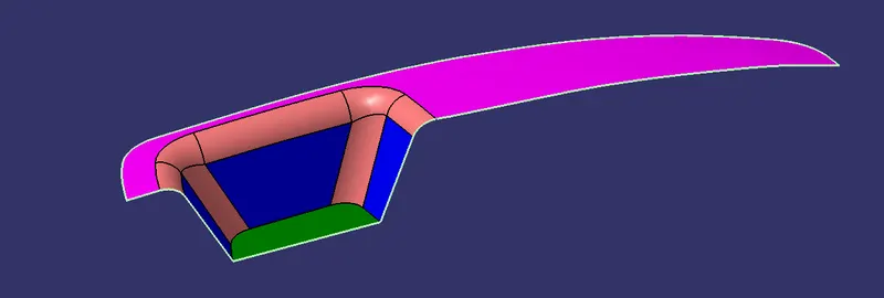
Switch bezel is a car part which contains switches and buttons to control different functions like window control,door lock,media etc. It is located at the inner portion of the door. The procedure used to create the part was same as the base bracket one. Class A surface was used to create the tooling axis. Class B surface was created at a distance equal to the thickness which was the identical surface of class A. Class C was formed as the wall of the model and then all the three surfaces were joined together and draft analysis was carried out.
Procedure:
A ) Tooling Axis Creation :
- Extract the face in which axis we have to create the tooling axis.
- Create a point on class A surface with the aim to move the main tool for component creation .
- Mask an axis over the point created with the same directions as the main axis
 .
. - Make a positioned stech
 in YZ plane, us the intersect option to get the bisected geometry.
 - After creating the intersecting lines select the Line command and join the vertices which show the most possible +ve draft angle manufacturable
 .
.
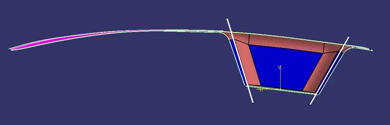
- After creating these two lines use the bisect option from the line command, to get the tooling axix in Y direction.
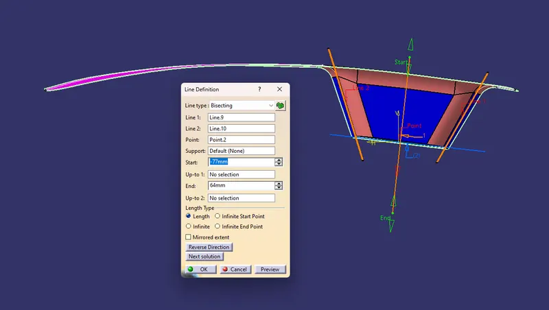
- We will repeat the same steps, to get the tooling axis in X direction.
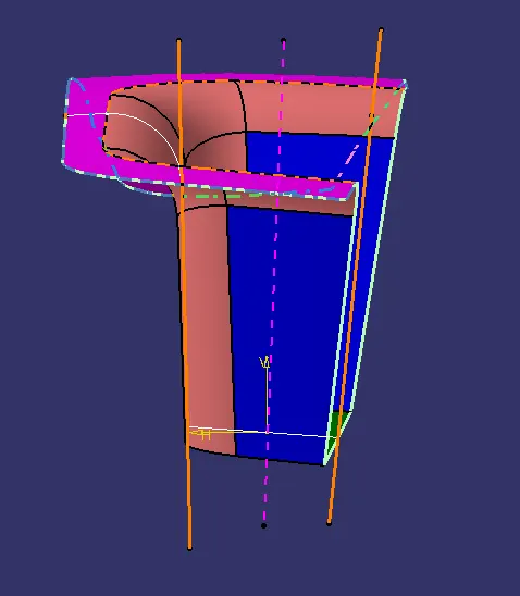
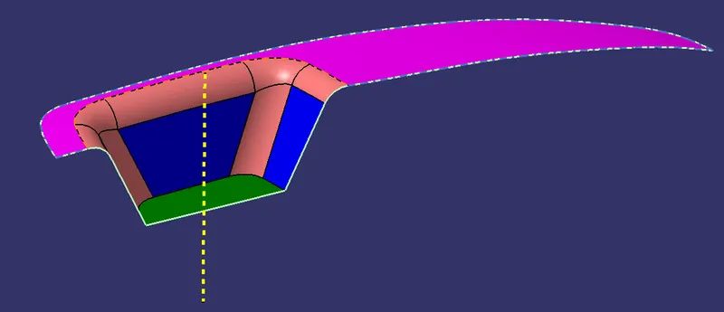
- After getting the tooling axis in X & Y direction, we will again use the bisect option to get the final tooling axis.
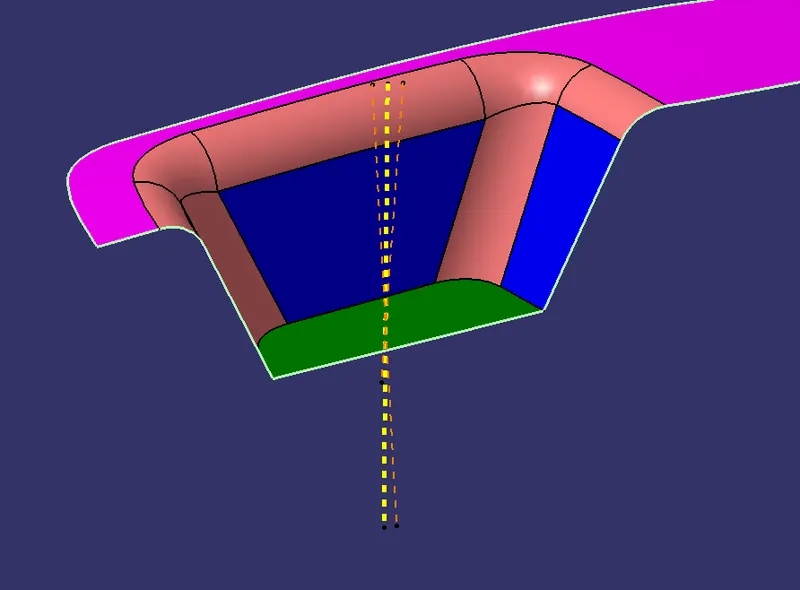
- The tooling axis for manufacturing the part is created.
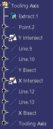
Tree Structure :
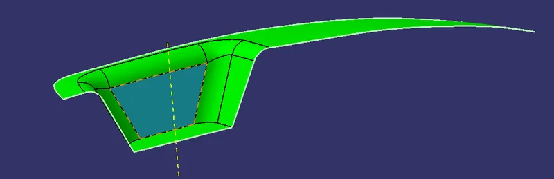
B) Draft Analysis of Class A Surface:
- After Tooling Axis Select the Feature Draft Analysis option from the Insert > Analysis > Feature Draft Analysis Option
 .
.
- Select the element to analyze.
- Next click on Use the compass to define the new current draft direction option and make it align with the tooling axis by dragging it to the axis
 .
.
- Next use the lock option
 to lock the compass to the tooling Axis.
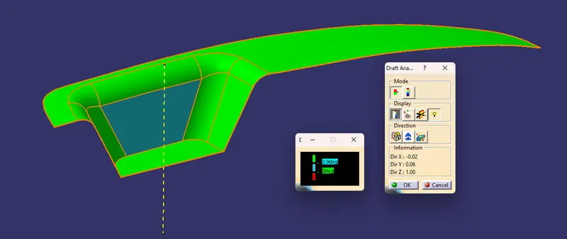
- If the color appears blue just click the invert option on the right side of the draft direction axis button
 .
.
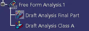
Tree Structure :
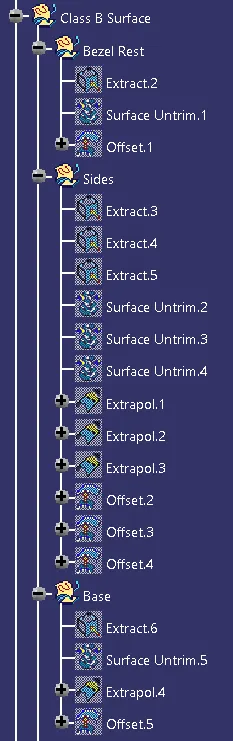
C ) Creating Class B Surface Creation:
- Using the Extract option select the Bezel Rest from the Class A surface
 .
.
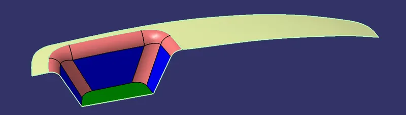
- Similarly we will use extract for sides, and base also.
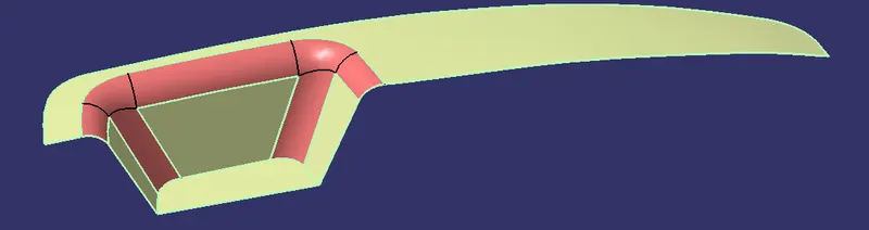
- then use untrim option
 to remove trims and get original shape.
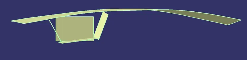
- Then use the extrapolate option
 to get rid of any gaps between the intersectios.
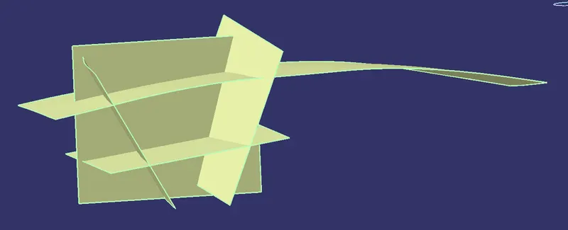
- then give offsets of 2.5 mm for desired thickness.
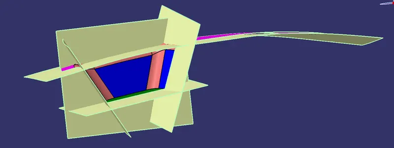
- then use the trim option to get the required shape.
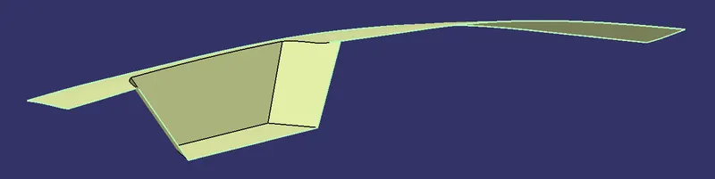
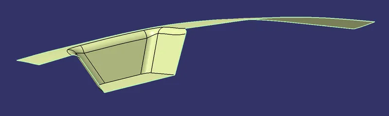
- after this use the fillet option to give the fillets as class A. As we are giving offset we have to give radius+thickknees for fillet input.
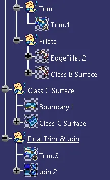
D ) Class C Surface Creation:
- Use the boundary command
 to get the edge of the class A.
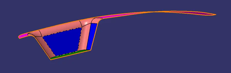
- use the sweep command
 and give the boundary, tooling axis and draft angle as input to get the Class C Surface.
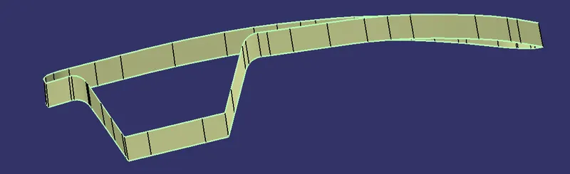
- Use the join command
 to join the class C & Class A Surfaces.
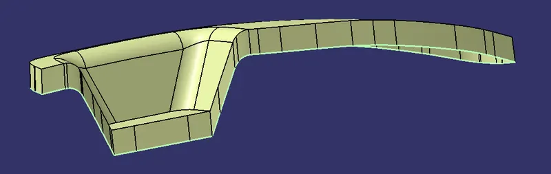
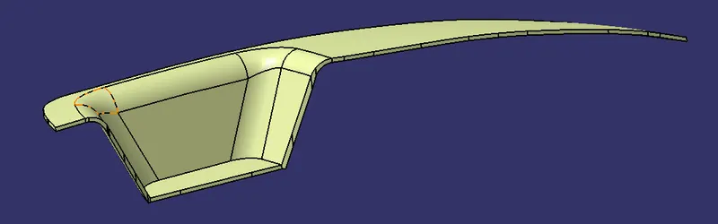
E ) Final Creation:
- Use the Joined Surface & Class B Surface and make a trim.
F ) Closed Surface:
- Go to Part > Body > Closed Surface command
 and we have a final solid part.
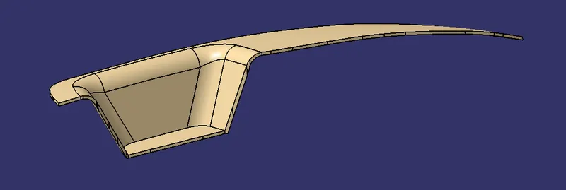
Tree Structure Class B & C Creation :
Draft Analysis For Class A Surface
Draft Analysis For Final Closed Surface
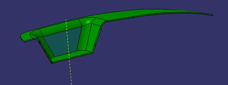
Views
Isometric
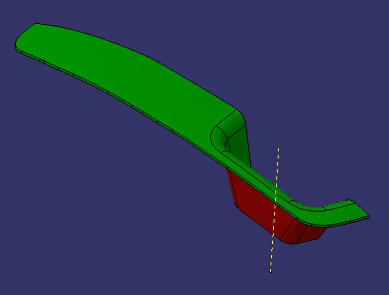
Front
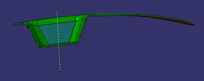
Side
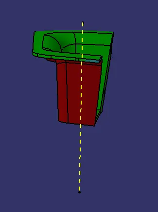
Top
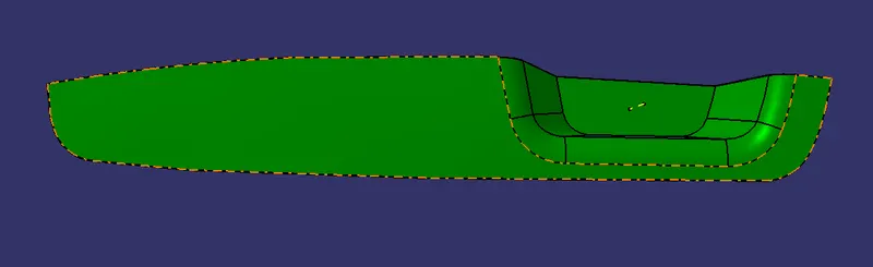
Conclusion : Created the plastic component in Catia V5 using the given Class A Surface.
- Created the tooling axis.
- Ceated the Class B Surface.
- Created the Class C Surface.
- Created the Closed Surface from Surface geometry.
- Published the Class A, B & C Surface, Tooling Axis & Closed Surfaces.
- Did the Draft Analysis.