Week 9 - Challenge 2 - Switch Bezel Design
AIM
To Create the Switch Bezel Plastic component through the given Class-A surface. To begin with, the tooling axis for the given Class-A Surface should be created meeting the requirements of the draft angle and at the end perform the Draft analysis on the model.
GIVEN
Thickness of the component to be 2.5 mm
TREE STRUCTURE
OVERALL TREE STRUCTURE
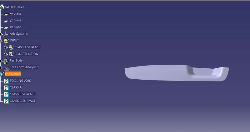
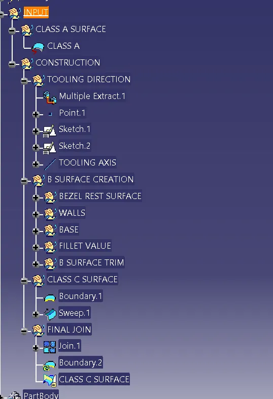
INPUT
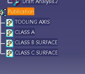
PUBLICATION
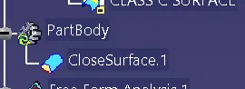
PART BODY
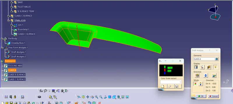
DRAFT ANALYSIS
TOOLING DIRECTION
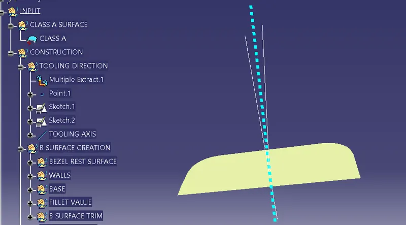
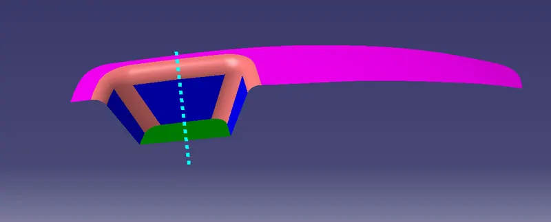
DRAFT
STEPS
- Set the customized render style
- Select the Draft analysis Tool
- Adjust the draft direction to moulding axis using the compass
- Observe the colour ranges
GREEN - 3 degree above
RED - 0 degree below
BLUE - 0 ~ 3 degree
DRAFT ANAYLYSIS
CLASS A SURFACE
CLOSE SURFACE
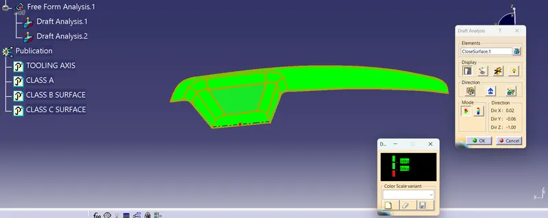
VIEW
ISOMETRIC VIEW
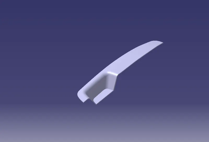
FRONT VIEW
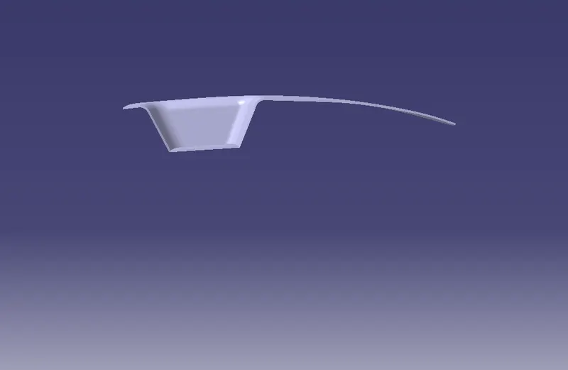
SIDE VIEW
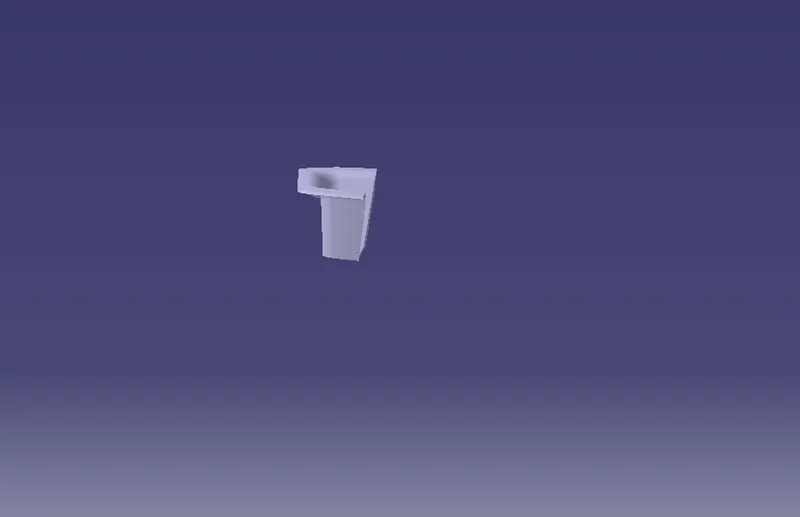
TOP VIEW
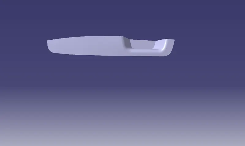
DETAILED REPORT
- To open the given CLASS A SURFACE
- Insert a new geometrical set name it as CONSTRUCTIONS in this Geometrical set. we create TOOLING DIRECTION
- IN TOOLING DIRECTION Extract the base and create a point centre of the surface
- Create sketch using position sketch with the AXIS and Create a LINE1 & LINE 2. Open bisecting line and remaining to be construction element
- After that OPEN position sketch with the another axis and create line and the angle 4 degree
- BISECTING THE two lines and TOOLING AXIS to be created
- Create geometric sets BEZEL REST SURFACE, WALLS, BASE, FILLET VALUE, B SURFACE TRIM
- Create C SURFACE
- OPEN BOUNDARY AND SWEEP.after that join the class A & CLASS B SURFACE
RESULT
Thus,the Switch Bezel Plastic component through the given Class-A surface. To begin with, the tooling axis for the given Class-A Surface should be created meeting the requirements of the draft angle and at the end perform the Draft analysis on the model to be completed.