Week 9 - Challenge 2 - Switch Bezel Design
Report
Aim :
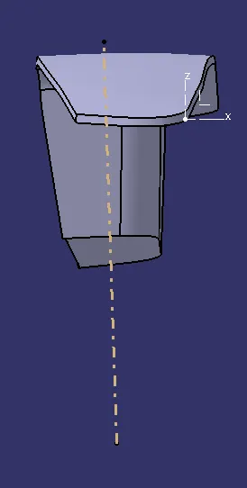
To create the Switch Bezel Plastic component through the given Class-A surface. To begin with, the tooling axis for the given Class-A Surface should be created meeting the requirements of the draft angle and at the end perform the Draft analysis on the model.
Take the thickness of the component to be 2.5 mm.
Theory :
Tooling Direction -
It determines the direction at which the mould would be pulled apart, draft angles are set with respect to the tooling direction. We use the Bisection method to determine the tooling axis, which is done by following the below mentioned steps.
- Locate a surface where the sides of the given part might create interference with the draft angle.
- Create a point in the middle of the surface. Also create an axis system on that point or two planes perpendicular to the surface of the point.
- Take intersections with the perpendicular plane on the part.
- Locate the sides that might interfere with the draft angle. Create lines on either side and take a bisector to create a reference tooling direction on that plane. If there is only one side that could cause interference, then create a line which is at an angle equal or more than the draft angle from the side.
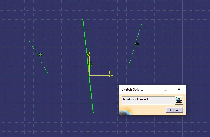
- Repeat the steps 3 & 4 for the second perpendicular plane. Thus resulting in 2 different tooling axes.
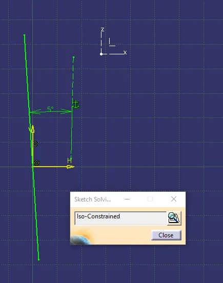
- Take a bisector line to the 2 reference axes. This is the final Tooling axis that determines the tooling direction.
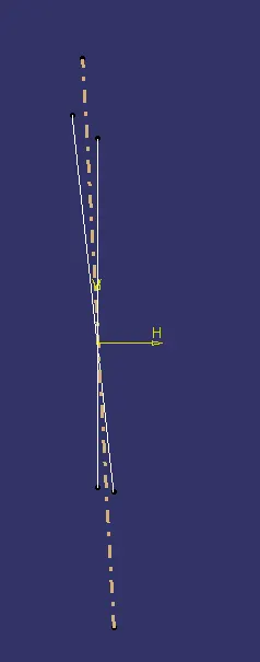
Design of the part -
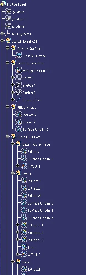
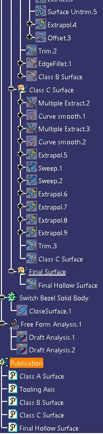
- Check the surface continuity of the input surface, repair discontinuous surfaces. This is the Class A surface.
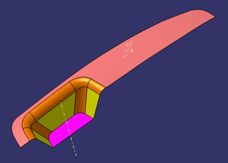
- Determine the Tooling axis on the given Class A surface.
- Extract all the surfaces (excluding the fillets), un-trim them and offset all the surfaces by 2.5mm to get the surface when thickened.
- Extrapolate each surfaces so that they intersect with each other. First, Trim the vertical surfaces together. Then, trim the top and bottom surface to the vertical surface.
- Apply edge blends after considering the thickness required and the direction of the fillet.
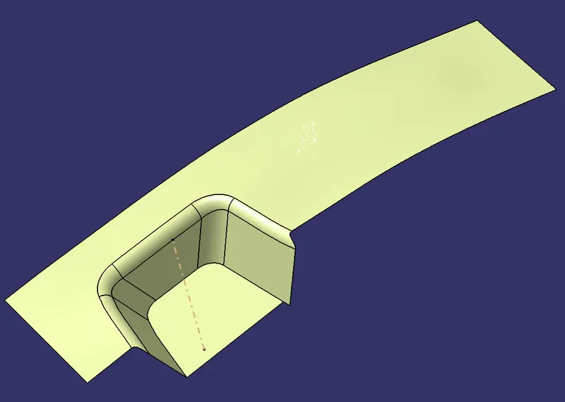
- This surface is the Class-B surface.
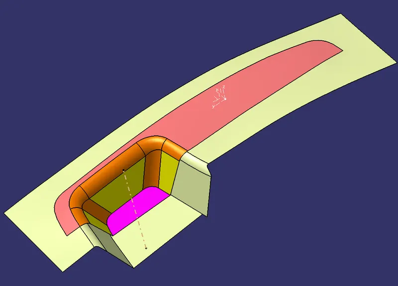
- Extract the boundary of the Class A surface, smoothen the curves.
- Use the Curves produced to sweep a surface towards Class-B surface, with the drafting axis in consideration and a draft angle of 3deg. This is the Class C surface.
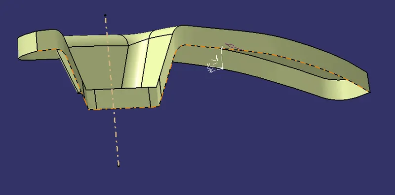
- Extapolate the Class A surface and trim it using the surface produced after the sweep operation. To combine the Class A surface with the Class C surface.
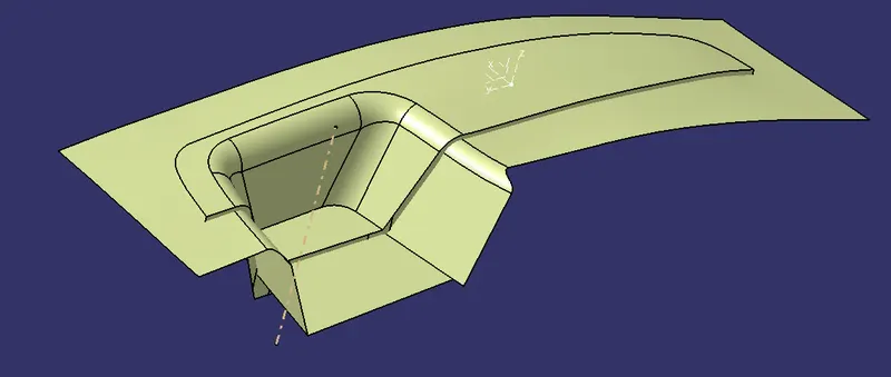
- Trim the resulting surface with the Class B surface to get the final hollow closed surface.
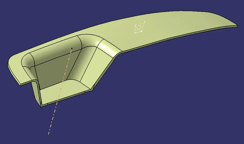
- Go to the part workbench and use the closed surface tool in surface commands to create a solid part from the hollow surface. This is the final product.
Isometric view:
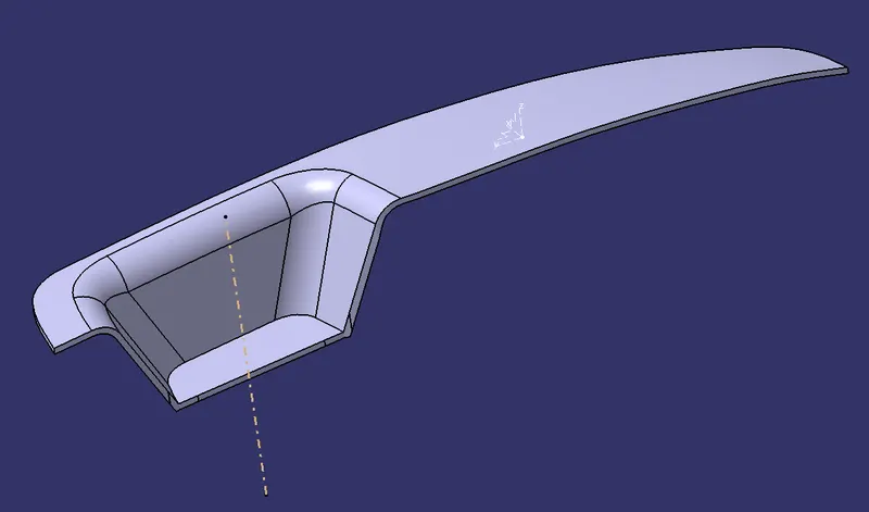
Front View:
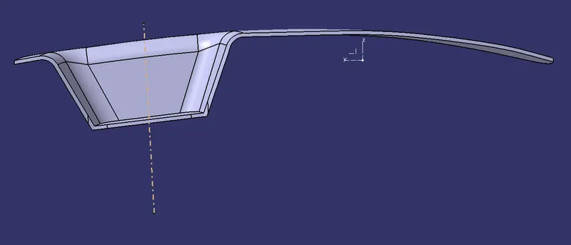
Top View:
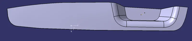
Side View:
Tree Structure-
Draft Analysis -
It helps to detect if the designed part is easily removable from the mould or die used to manufacture it. A Mould is used for plastic components, whereas a Die is used for sheet metal components. All plastic components will have a minimum draft of 0.5 to 3deg and the draft will be 7deg or more for automotive sheet metal parts.
If a mould wall is perpendicular to the part ejection, there will be friction or interference between the mould and the part which will either deform the product or not allow it to release from the die/mould. This is why design engineers give a minimum draft to the part. If there is a negative draft, then it will be impossible for the product to be released from the mould.
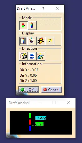
Draft Analysis command window in CATIA V5 -
- Commands in the Mode section of the window can be used to switch between Quick analysis mode and Full analysis mode.
- The first command on display section is used to show or hide the colour scale.
- Ananlysis command in the Display section of Draft analysis can be used to find the relative angle od surface to the draft angle at each specific point.
- Highlights can be switched on and off using Highlight representation. The light effect can be changed for better clarity/ shading on the surface.
- The lock commands locks the compass in place.
- Compass command allows us to move the compass to align to the required tooling axis.
- Inverse command reverses the tooling direction.
Procedure for draft analysis -
- Check the boundary of the product/surface by using the Boundary/ Join/ Disassemble commands. Make sure there are no discontinuities.
- Change the mesh in View Mode Customization to Material for draft analysis.
- Find and click on the Draft analysis command in the toolbar or go to Insert> Analysis> Draft Analysis.
- Change the upper limit to 2.9deg to allow for a draft angle of 3deg.
- Click on the compass command and drag the compass onto the tooling axis.
- Click on the surface that needs to be analyzed.
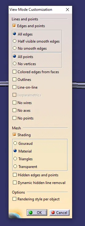
- This procedure is to be done on the Class-A surface and the final Solid Part.
Draft Analysis of the Class-A surface -
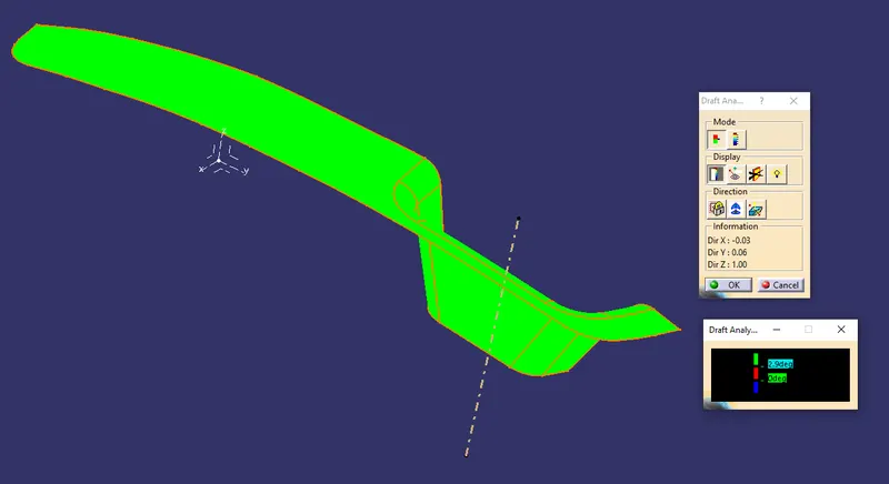
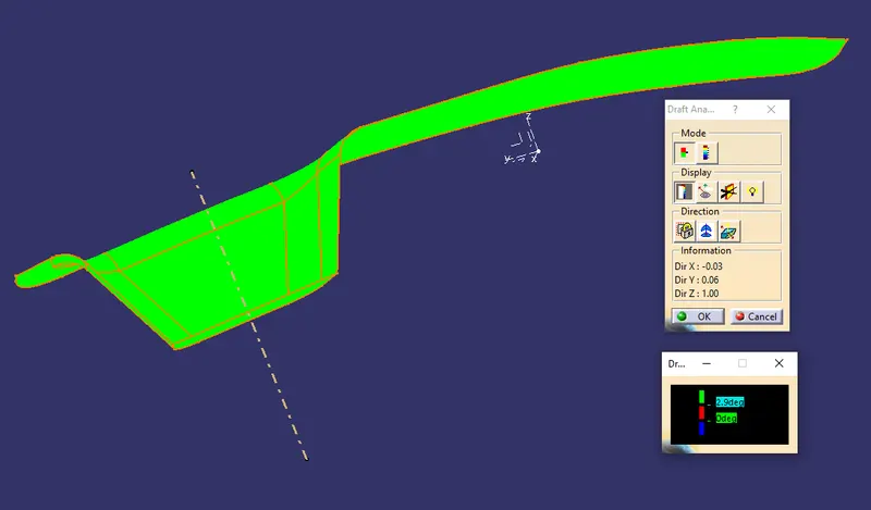
Draft Analysis of the final solid surface -
Isometric View:
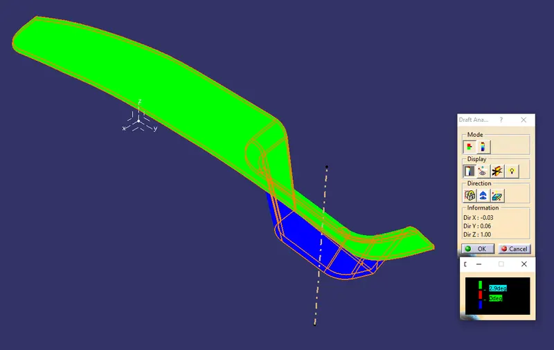
Side View:
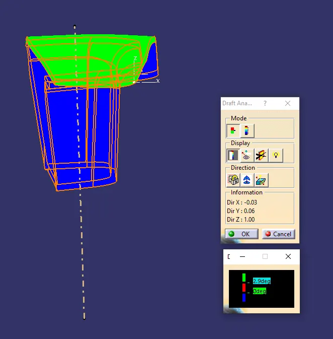
Front View:
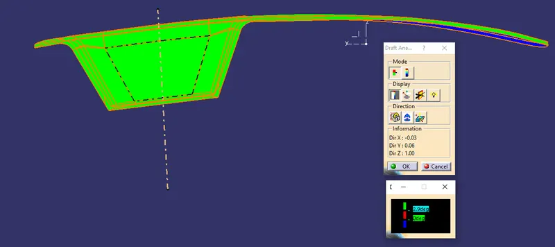
Top View:
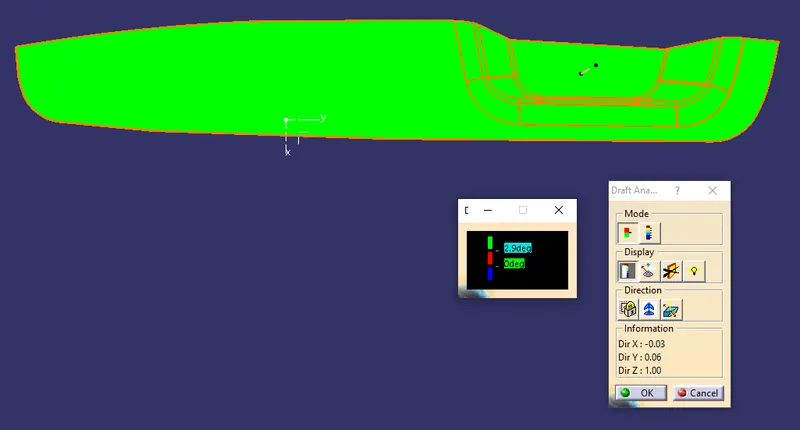
Result And Conclusion -
- The desired part is produced by taking the draft requirements and thickness into consideration.
- Draft analysis is conducted on the Class A surface and the final solid part.