Fender Design
AIM -
To design a fender’s necessary mounting points using the given Mastic data and fender-skin.
Fender
A fender is a the part of a vehicle over the wheel-well. It’s mainly used to prevent the spray of rocks, sand and other road debris from flying onto the car body and to prevent the same from being thrown onto traffic and pedestrians by the rotating tires (similar to the mudguards used for bikes and 2-wheelers). Cars have a pair of front-fenders and a pair of rear-fenders.
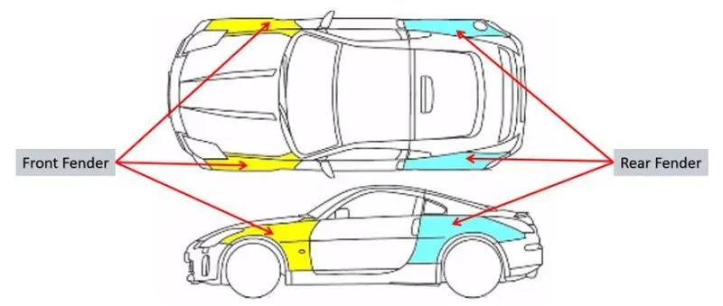
Types of Fenders
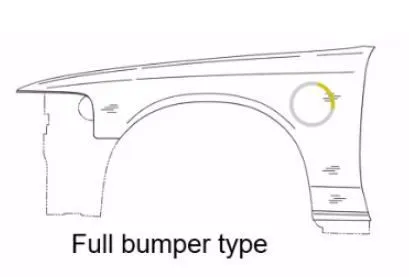
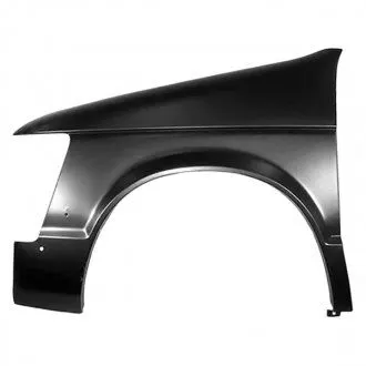
- Full Bumber Type
These fenders covers the full front area till the lights and the end of the bonnet of a car. These take longer and more material to produce, per piece.
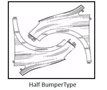
- Half Bumper Type
These don’t cover the whole light mount are and takes much less amount of material than the other type. Two of these could be manufactured for relatively same amount of material which would be used for full-bumper type fenders.
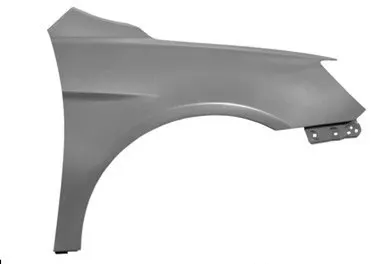
Design of a Fender
- Design Requirements
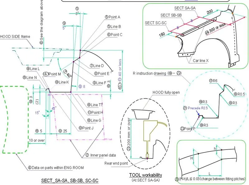
The dimensions are as provided by the master-section.
- Functional Requirements
- Should prevent all the mud, rocks, sand, soil, liquidsand other road debris from hitting the engine and other parts of the car.
- Should also prevent the above said road debris from being thrown onto traffic and pedestrians by the rotating tire.
- Should aid in the aerodynamics of the car.
- It limits the car components’ exposure to harmful-corrosive elements.
- Gap and flushness requirements
- Should follow the different design and safety regulations of different parts of the world.
- Dimensions of the fender should take into account the wheel size, suspension travel, the full range of tire motion, toe & camber angles and the extra clearances required so that the whole part doesn’t touch the insides of the wheel well.
- Safety and Crash regulations
The region 1000mm-1350mm from the ground is the child impact zone and region 1350mm+ is the adult impact zone on the fender/sides of a car. The fender and sides should crumble without transferring the forces in to the cabin and passengers. (Crash test - Small overlap, 25 % Offset, 40mph).
Mounting Points
- Sill area
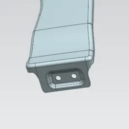
It’s at the bottom of the fender and is to be joined with the skirt/sill of the car. Fasteners are used for mounting.
- Baffle area
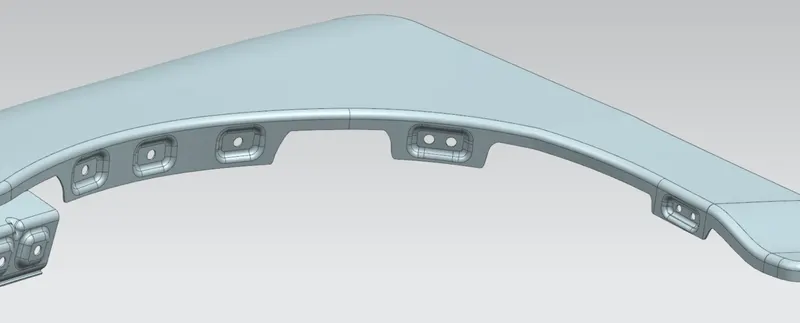
They are on the underside of the fender/ wheel-arch and prevents the splash & road debris from spraying to the sides of the car. Mostly plastic/ metal clips are used, but fasteners can also be used for mounting.
- A-Pillar area
The region at which the A-pillar cover and most times the rear-view mirrors are mounted. Fasteners are used for mounting.
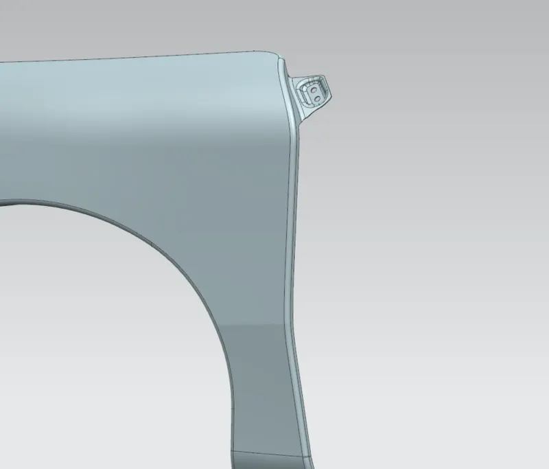
- Bumper area
The front bumper of the car is joined to the fender at this region.
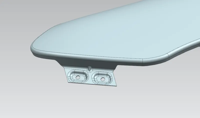
- Drip area
The area at which the fender Is attached to the engine compartment. The extra design considerations to be followed while design this area are -
- A clearance of 200mm-300mm for the cowl mounting area, near the A-pillar.
- A clearance of 150mm at the front part for the head-lamp housing unit.
Mounting is done using fasteners.
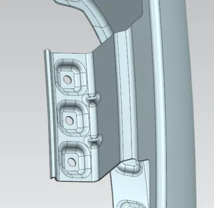
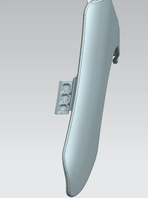
Design requirements for mounting points
- The sheet surface can be extended by 10mm-15mm for providing appropriate surface for mounting points.
- All mounting points should have a 5mm hole for fasteners, 10mm region of flat surface for the fastener head to be seated. Except for the baffle region where the radii can be reduced to 4mm and 8mm.
- Embosses are of 3mm-3.5mm depth. The face/ edge-blends are to be given a radius of 2mm-3mm.
- The edges and corners should be smooth to prevent concentration of stress, necessary relief is to be provided if in case of sharp corners.
- Darts are to be provided at longer strips of regions for fortification of the structure.
- The thickness of the fender should be 0.75mm, in the inwards direction.
Conclusion
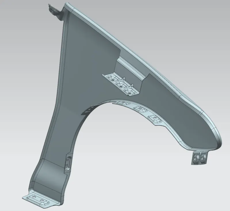
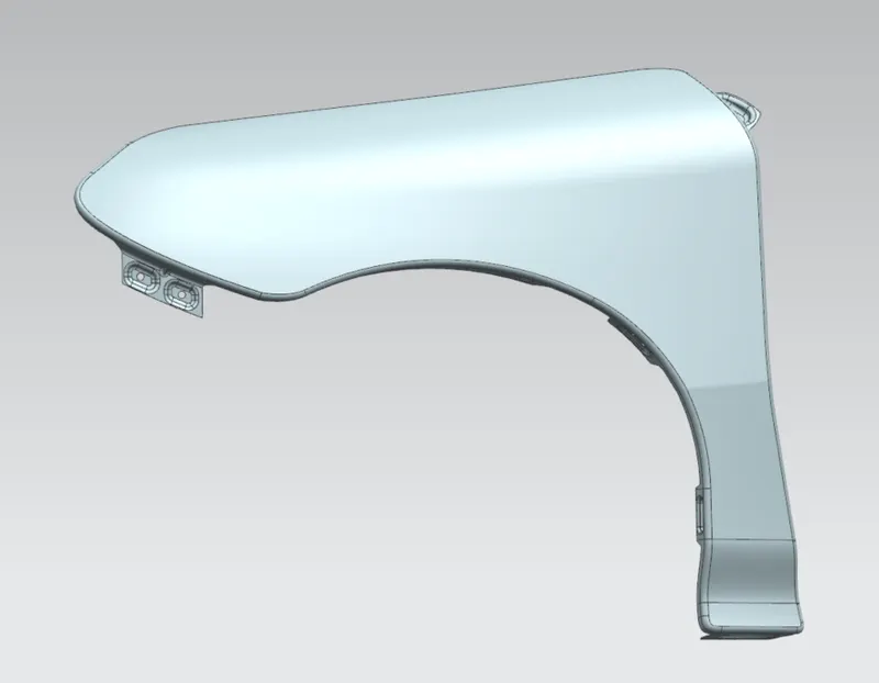
The required mounting points at the drip area, bumper, sill, A-pillar and baffle area is designed.