Week 9 - Challenge 2 - Switch Bezel Design
Here we Creating the Switch Bezel Plastic component through the given Class-A surface. To begin with, the tooling axis for the given Class-A Surface should be created meeting the requirements of the draft angle and at the end perform the Draft analysis on the model.
For Creating the Switch Bezel Plastic component through the given Class-A surface. Firstly we have to create the TOOLING AXIS, CLASS B SURFACE, And CLASS C SURFACE from the CLASS A SURFACE. After creating these surfaces we have to check the surface connectivity and then Use the Close Surface feature to make a solid body from the surface.
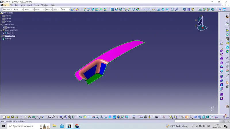
Given CLASS A SURFACE
---------------------------------------------------------------------------------------------------------------------------------------------------------------------------------------------------------------------------------------------------------------------------------------------------------------------------------------------------------------------------------------
Now creating the TOOLING AXIS
extracting the base surface for the creation of the axis
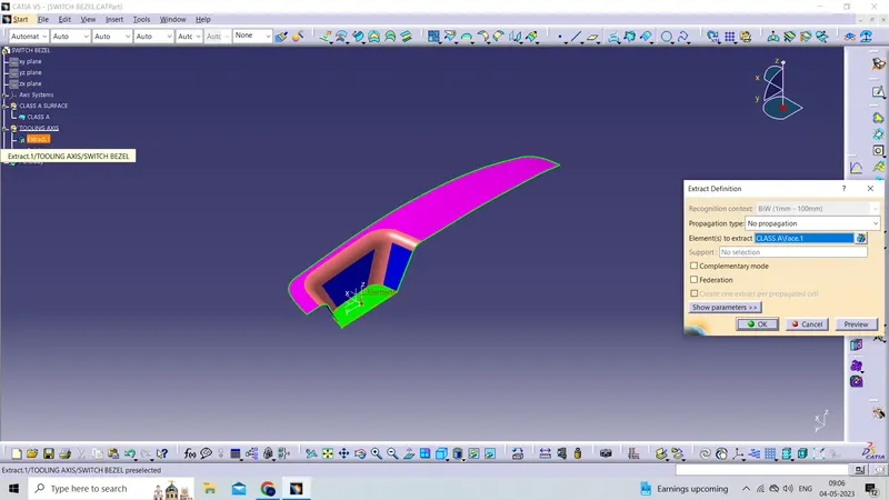
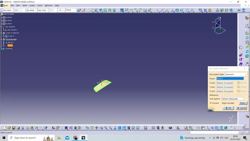
then creating a point on the extracted surface and creating the axis system on the same point
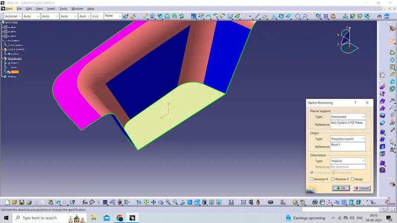
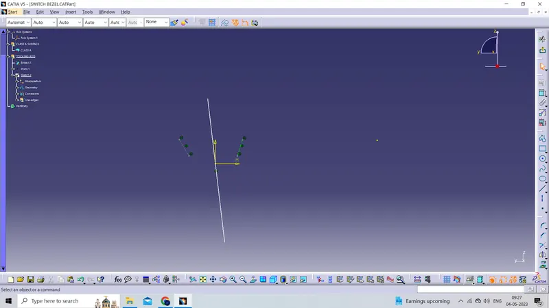
Now creating the position sketch along the yz plane
TOOLING AXIS for the Y-direction
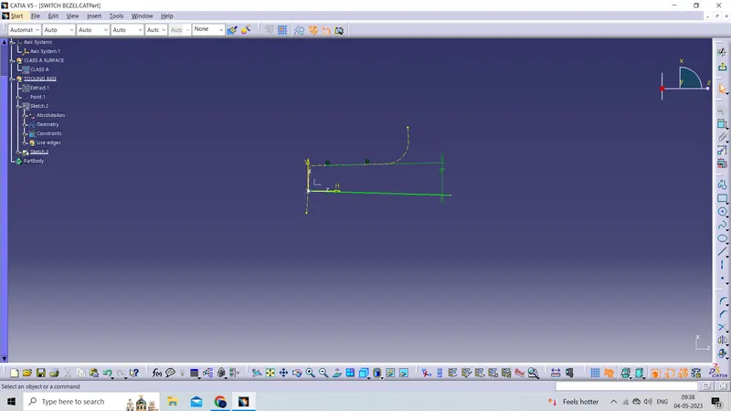
TOOLING AXIS for the X-direction
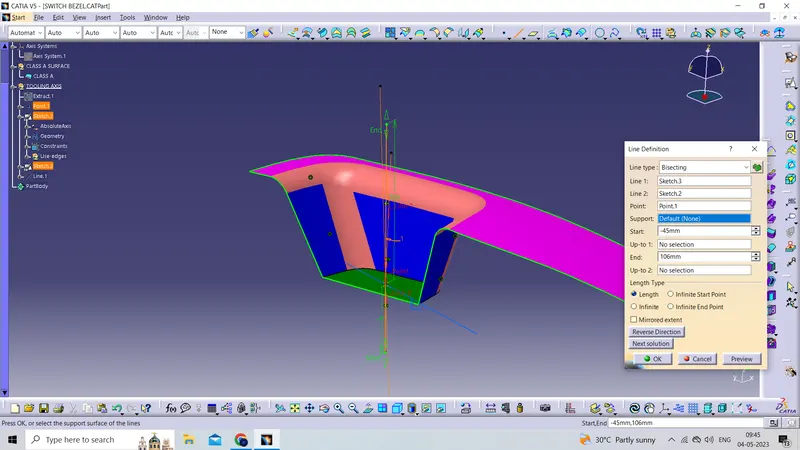
Now for the main TOOLING AXIS bisecting the Y-direction TOOLING AXIS And X-direction TOOLING AXIS
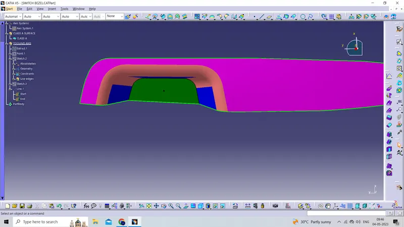
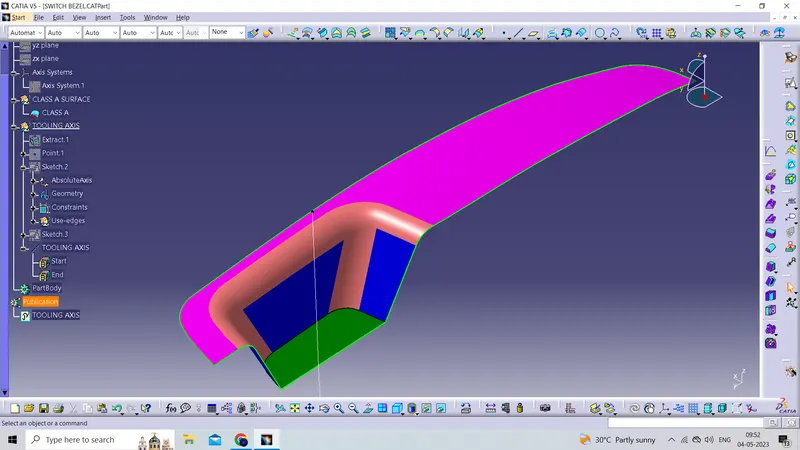
For checking whether our TOOLING AXIS is correct or not put the axis in the normal view if, in the normal view(normal view shown below), all surfaces are visible then our tooling axis is correct
After that published the TOOLING AXIS And CLASS A SURFACE
---------------------------------------------------------------------------------------------------------------------------------------------------------------------------------------------------------------------------------------------------------------------------------------------------------------------------------------------------------------------------------------
Now Creating The CLASS B SURFACE
first, extract the bezel rest surface in the bezel rest surface geometrical set
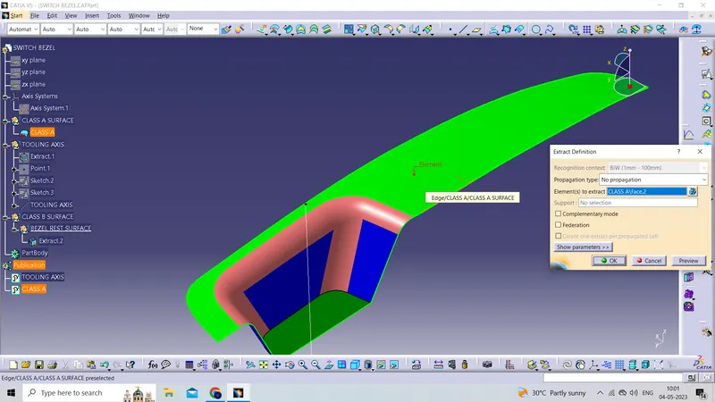
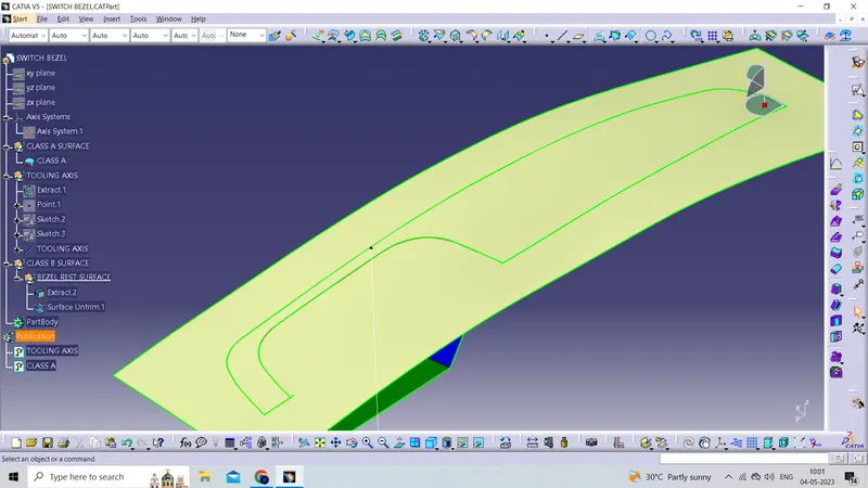
Now untrim the extracted surface
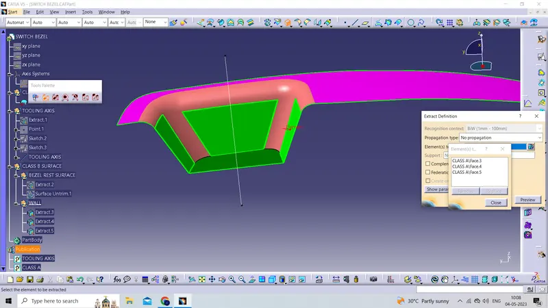
Now extract the walls in the wall geometrical set
Now untriming the extracted surface one by one
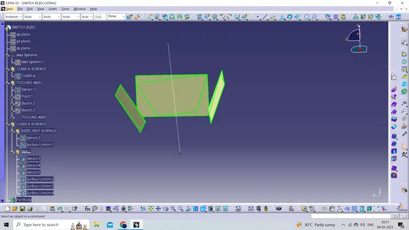
As we see the extracted walls And the rest bezel surface is not intersecting then we have to extrapolate the walls
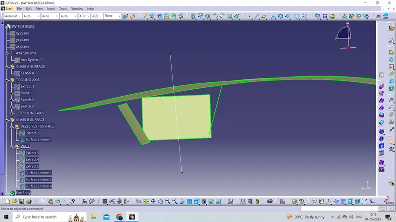
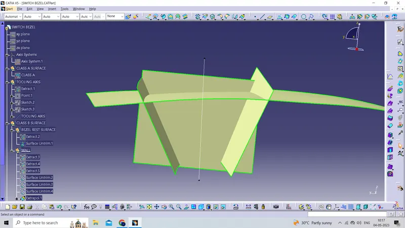
now here I change the color for a better understanding
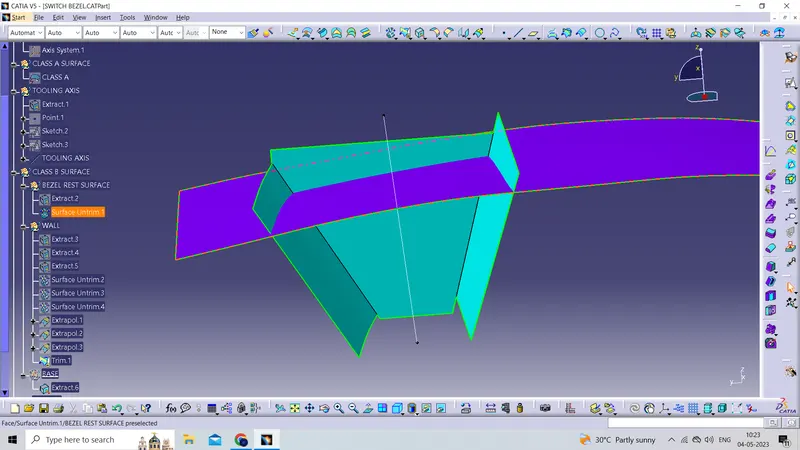
Now extracting the BASE surface in the BASE geometrical set
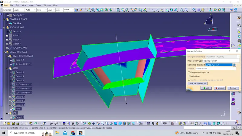
Now untrim the extruded surface
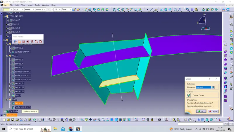
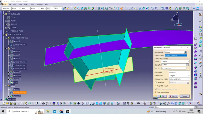
Now extrapolate the untrim surface
Now offset all the surfaces in their respective geometrical sets. (thickness of the component is given which means the offset value is indirectly given which is 2.5mm)
OFFSET BEZEL REST SURFACE
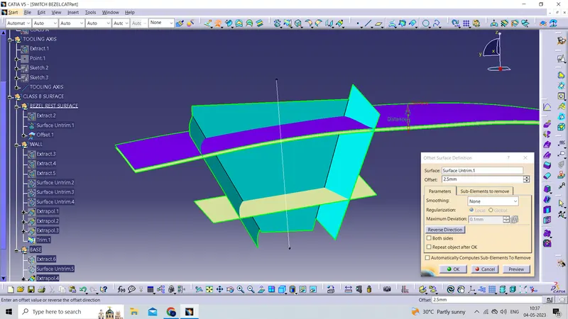
OFFSET WALL SURFACE
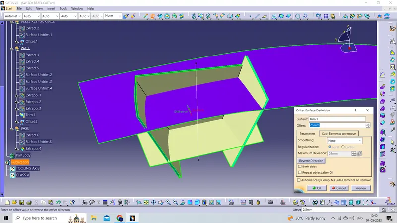
OFFSET BASE
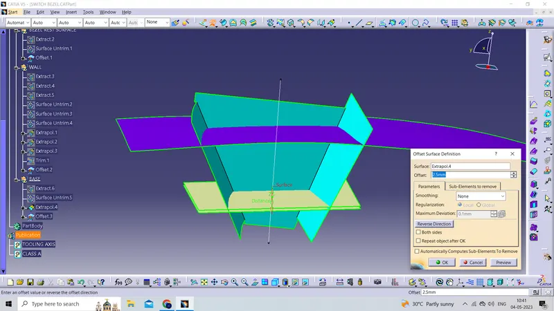
NOW TRIM THE CLASS B SURFACE
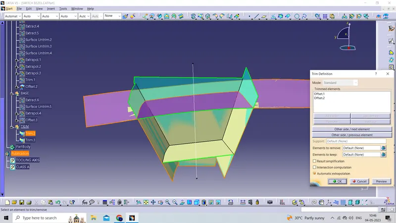
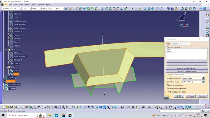
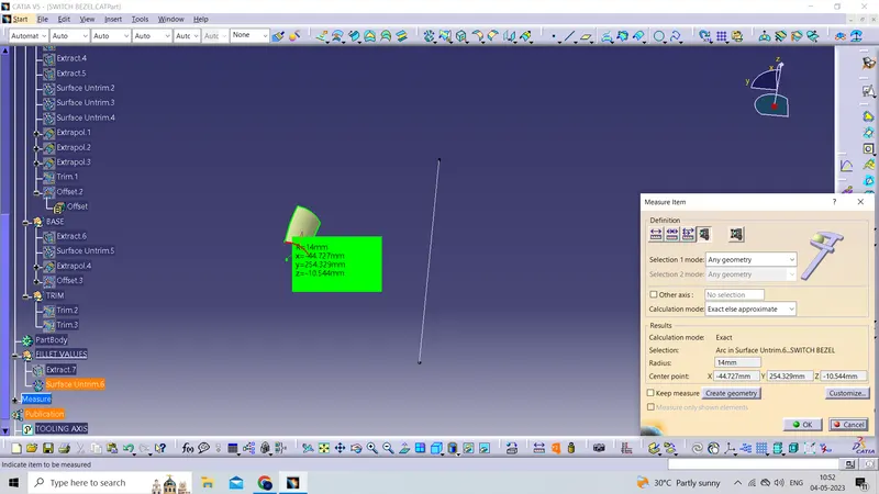
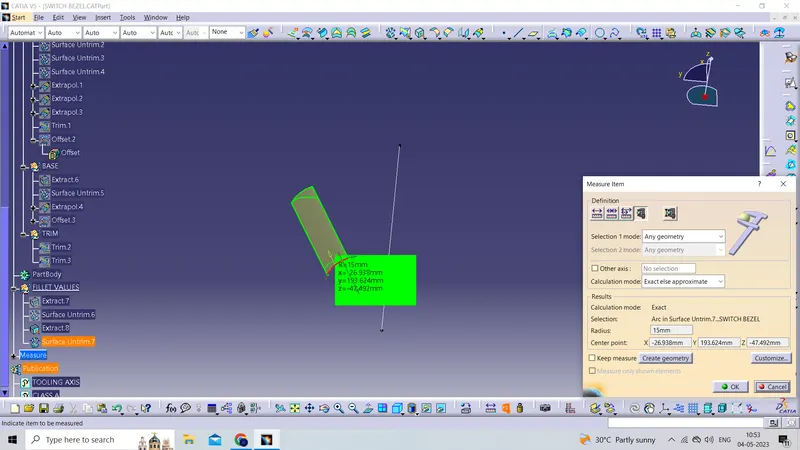
NOW CREATE A GEOMETRICAL SET FOR FILLET VALUES
Measuring the horizontal fillet radius
Measuring the vertical fillet radius
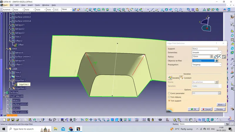
NOW USE THE EDGE FILLET COMMAND AND FILLET THE EDGES OF CLASS B SURFACES
---------------------------------------------------------------------------------------------------------------------------------------------------------------------------------------------------------------------------------------------------------------------------------------------------------------------------------------------------------------------------------------
Now Creating The CLASS C SURFACE
For creating a CLASS C SURFACE use extract with tangency to extract the patches from the CLASS A SURFACE shown below
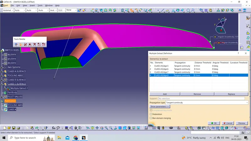
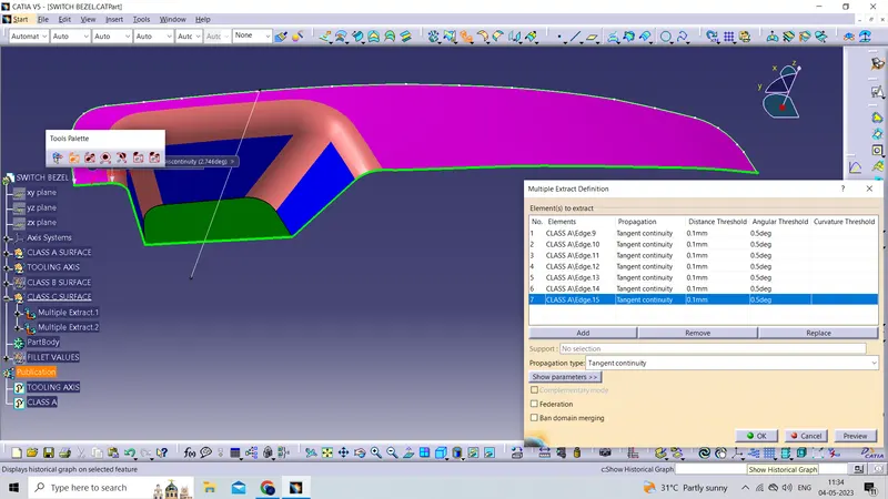
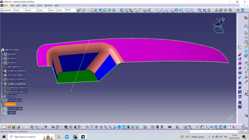
Now sweep the Multiple Extract.1 And Multiple Extract.2 one by one
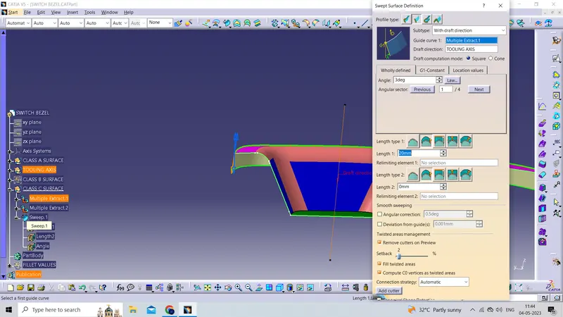
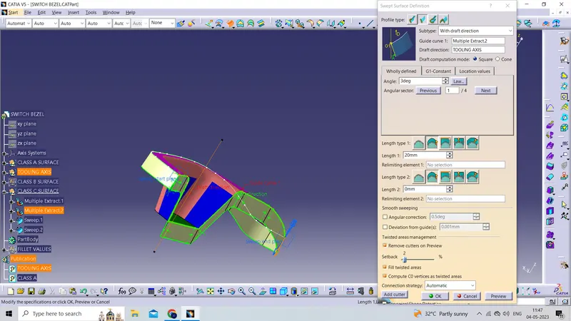
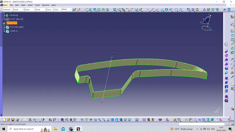
Now Extrapolate the Multiple Extract.1 And Multiple Extract.2 one by one
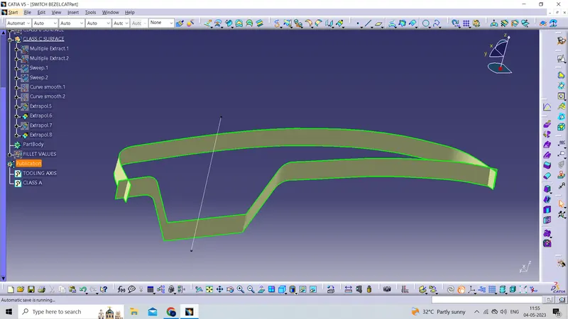
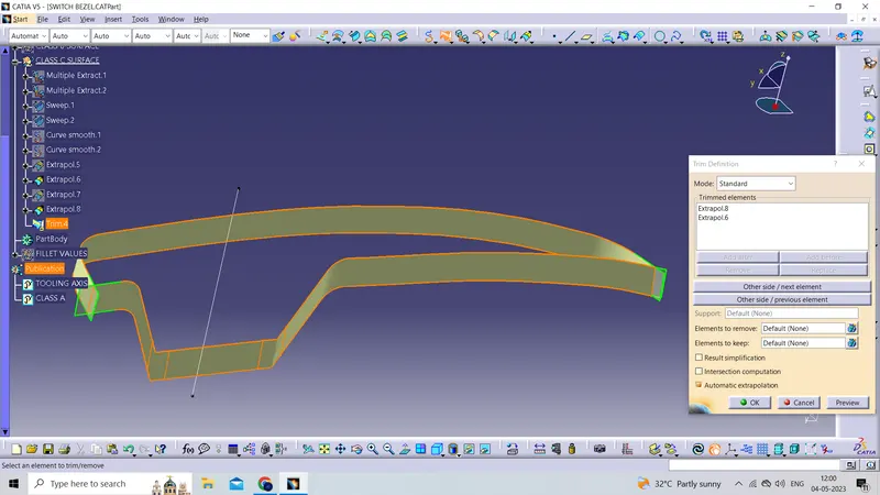
Now trim them together.
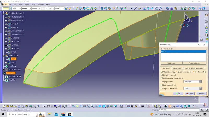
Now join the CLASS A SURFACE Ans CLASS C SURFACE in the FINAL JOINT Geometrical set
some boundries of the CLASS A SURFACE are broken for that once agaain trim and after that join still some boundry links are broken then go to join try to increase the Merging distance
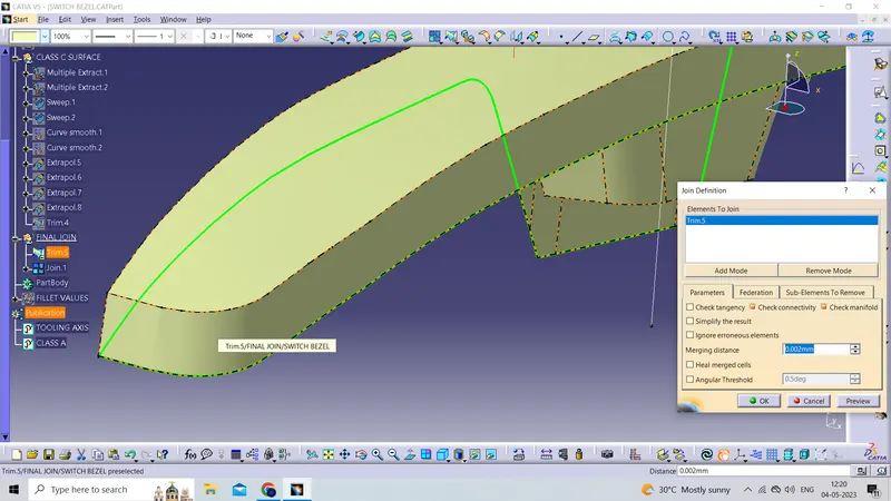
Now trim the CLASS B SURFACE with above join (join1.)
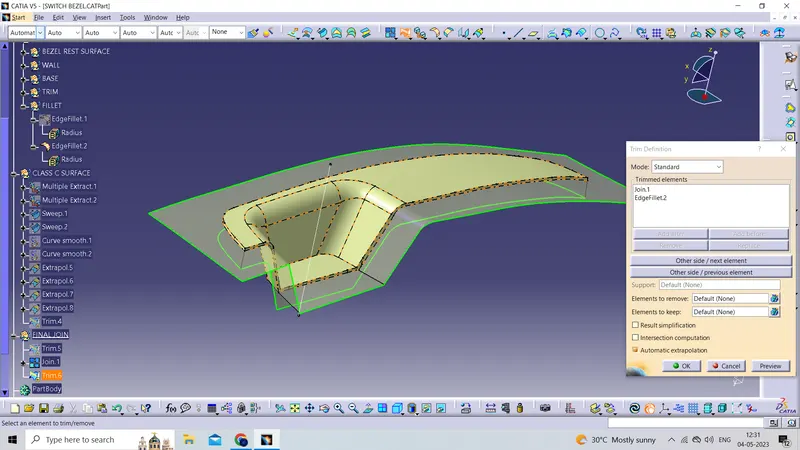
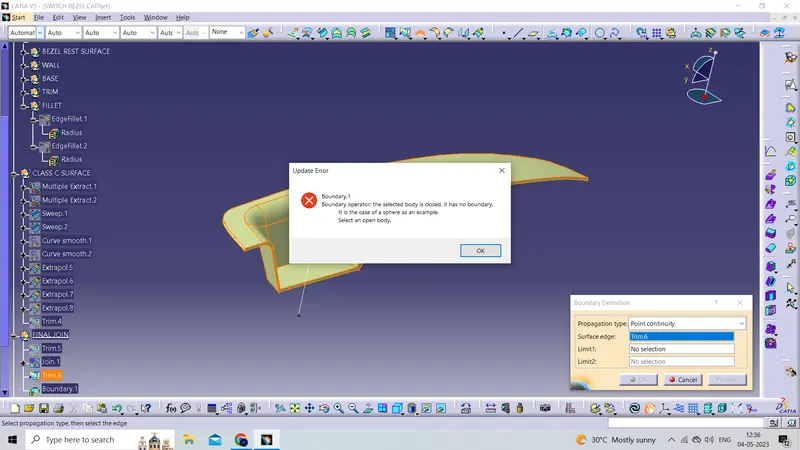
After above trim operation we get the close body. how to check it it close body try to creat boundry on it And if it dosn't form your output is coorect.(below picture show body is close or not)
---------------------------------------------------------------------------------------------------------------------------------------------------------------------------------------------------------------------------------------------------------------------------------------------------------------------------------------------------------------------------------------
Now Use the Close Surface feature to make a solid body from the surface.
goto part design
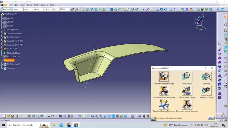
then select the close surface command
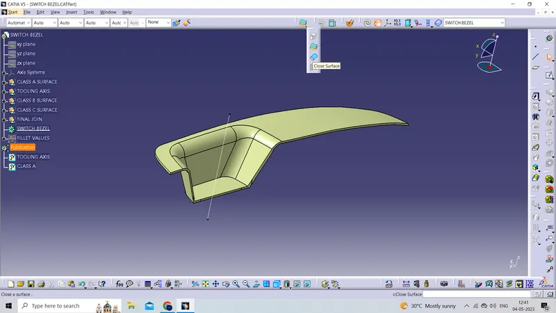
then select the trim6 click ok
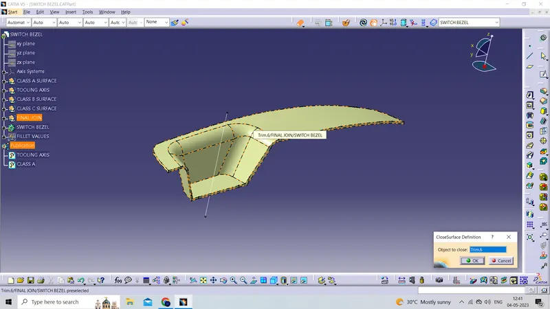
desired SWITCH BEZEL solid body part
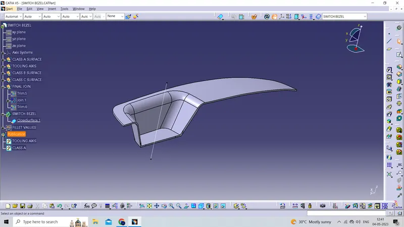
---------------------------------------------------------------------------------------------------------------------------------------------------------------------------------------------------------------------------------------------------------------------------------------------------------------------------------------------------------------------------------------
Draft analysis on the final plastic component
First put the model in material mode

then goto insert>>analysis>>Draft analysis
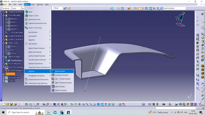
Now click on compaas command from the draft analysis window then the compass will come on the body
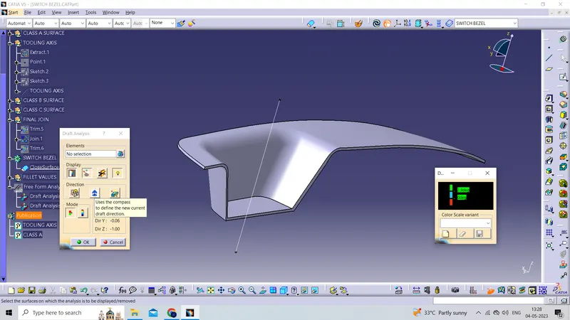
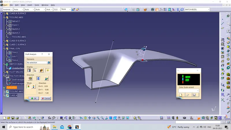
Now place the compass alog the tooling axis for the draft analysis and click on the analysis under running point for measuring the angle at different palaces on the body
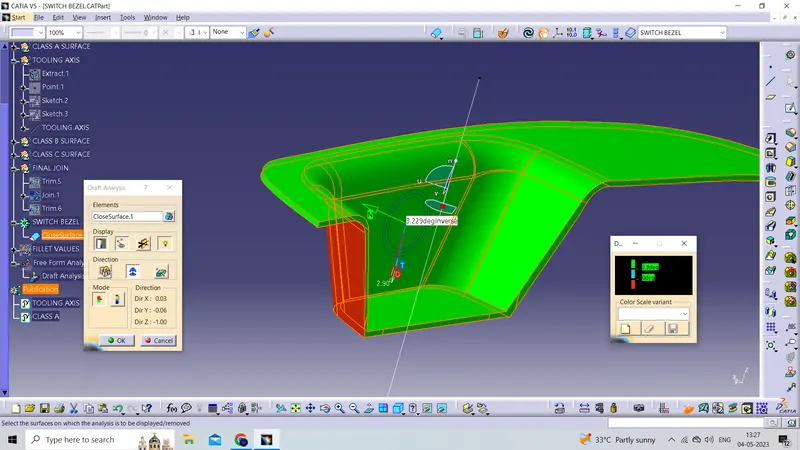
Isometric View
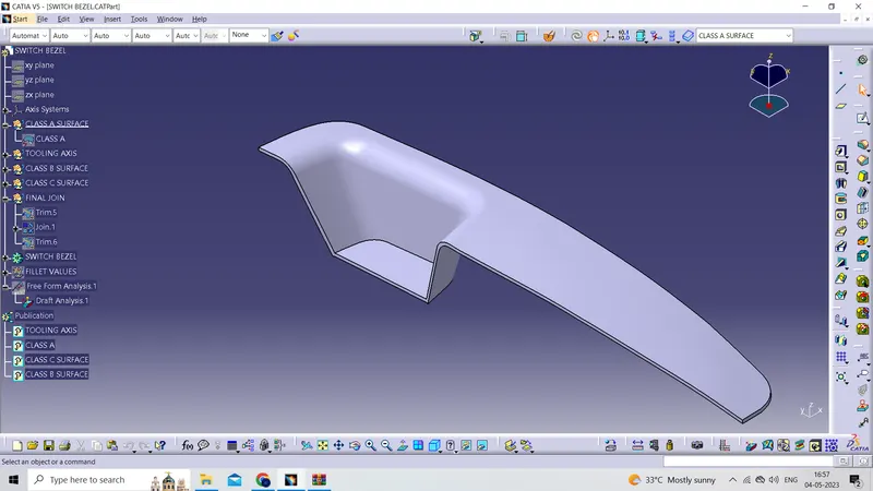
Front View
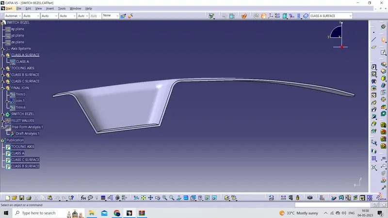
Side View
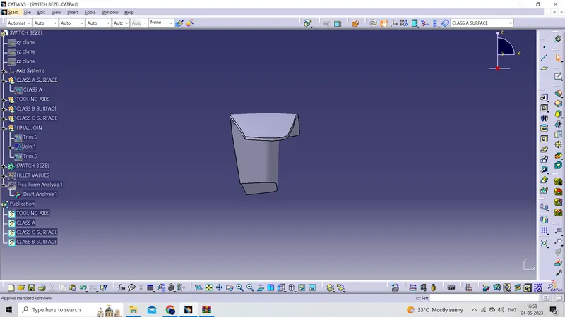
Top View

CATpart is submitted as an attachment using the below Browse option.