Week 9 - Challenge 2 - Switch Bezel Design
SWITCH BEZEL'S DESIGN AND DRAFT ANALYSIS
OBJECTIVE :
The project's goal is to create the necessary tooling direction with the aid of the bisecting approach, then design the switch bezel and perform a draught analysis for it.
INTRODUCTION :
The frame portion of the window switch that holds its switch covers and buttons in place is called the control panel bezel. Most OEMs produce the plastic parts of an automobile using the moulding process, therefore the switch bezel was created with this production factor in mind.
DESIGN IMPLICATIONS :
-
A surface should have good aesthetic quality and be smooth.
-
All the supporting elements, such as ribs, should be present in a class-B surface.
-
Since flashing couldn't impact the aesthetics of Class-A, the Parting Line should be parallel to the B surface.
-
The draught analysis should also pass for Class - C surfaces.
CREATION OF THE SWITCH BEZEL PROCEDURE :
The specified style surface is first examined for any irregularities, and if any are discovered, they are fixed using the commands Trim, Extrapolate, Split, and Join.
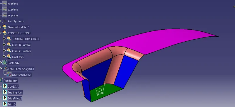
As you can see in the image below, the Class-A surface is flawless and free of any imperfections, so let's move on to the next phase.
CREATION OF TOOLING DIRECTION :
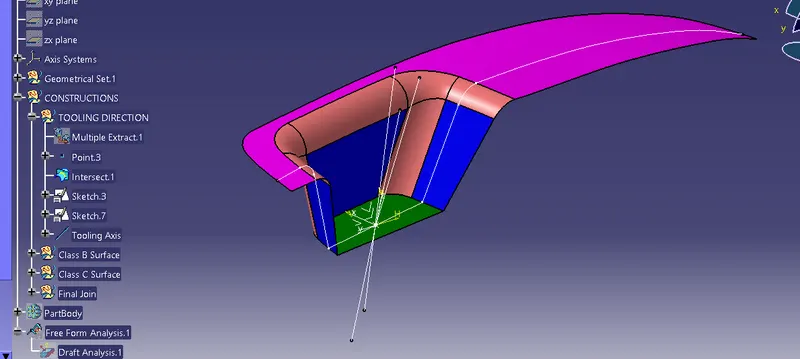
- Consider YZ plane as thereference plane for creating the tooling axis.
- By using Intersection command select the boundary of the class A surface and yz plane create a intersection line.
- Then hide class A surface and draww two lines on the intersection line which will bisect at some point.
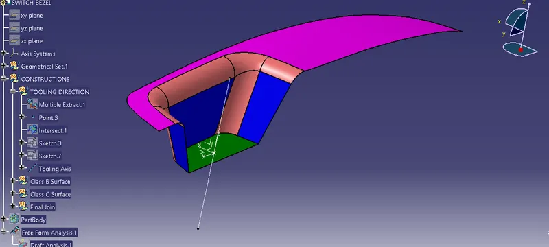
- Then using line command and bisecting method create a bisecting line.
- Now select sketch mode and similarly draw another bisecting line by selecting XZ plane,by giving some draft angle.
- Then from the above two bisecting lines create another bsecting line.
- That newly formed line is our Tooling Axis or Tooling Direction.
CREATION OF CLASS-B SURFACE :
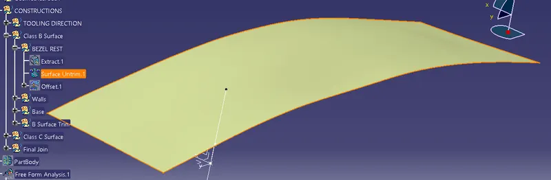
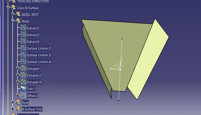
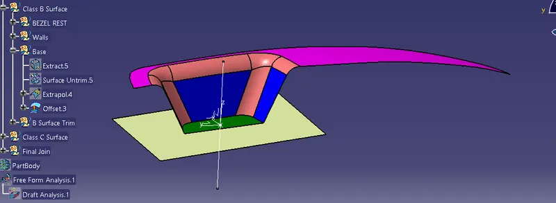
- For creating the class-B surface the required surface except the offset surface have been extracted and then untrimmed all the surface.
- Then all the surfaces have been extrapolated to get intersections between them.
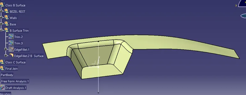
- Since the thickness of the Switch bezel is 3mm the B-Surface was offset to 3mm and the required trim operations must be carried out.
- Finally, the required corners have been filleted to 15mm and the top edge is filleted to 11mm.(14-3mm). [ 15mm,14mm(top edge) - fillet value of the A-surface, 3mm – Thickness of the component ]
CREATION OF CLASS-C SURFACE :
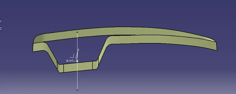
- The required outer edges of the A-Surface were extracted using Multiple Extract. Then for avoiding the patches the curve is smoothened using the Curve Smooth option.
- Then by using the sweep command the surface was created with the following feature controls,
- Profile type – Line
- Subtype – With Draft Direction
- Guide Curve – Smooth Curve
- Draft Direction – Tooling Axis
- Draft Computation Mode – Square
- Angle – 3 Degree
- Angle Sector – Positive Downward (1)
- Length – 20mm
- Then by using extrapolate command the edges were intersected between the surface corners which eases the trimming operation.
- Now the required portion of the C – surface were trimmed out.
FINAL JOINING OF CLASS A + CLASS B +CLASS C SURFACES :
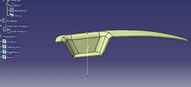
- After creating the c class surface,join the class A And Class B and class C Surface.
- Then using trim command remove the Unnecessary Surface.
CREATION OF CLOSED SURFACE :
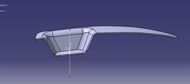
- Now the class – A and Class- C surfaces were joined together by removing the gaps in-between them with the help of extrapolation(tangent continuity) and Trim surface.
- Then the exact surface of the Switch bezel was trimmed from the above-resulted trim surface with the class-B surface.
- Then, by defining the part body by using the Closed Surface command in Part Design, the component's solid body is created.
PROCEDURE FOR CREATING DRAFT ANALYSIS :
- First the class – A surface is checked before creating the Class –B&C surface and finally the solid body must be analysed. Both can be done by following the below procedures.
- By changing the view mode to custom view parameters – Material mode then the feature draft analysis is enabled.
- Then the compass was activated and placed with the tooling axis by dragging the red pointer and then locked it.
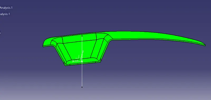
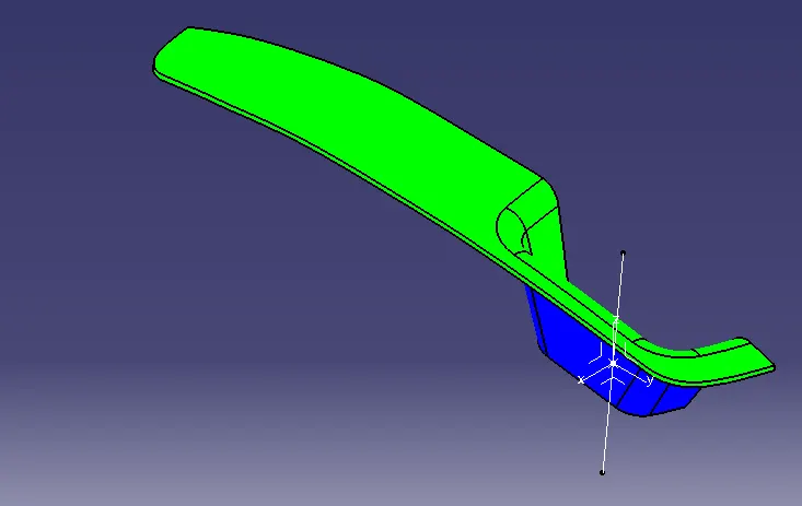
- Then, by selecting the quick analysis mode, the nominal value will be 3 degrees and checked for the component's draft angle.
- The green colour area shows that it satisfies the 3-degree draft angle. If not satisfied then by using the Running point tool the area is measured and then altered to get a successful draft for the created tooling direction.
TREE STRUCTURE :
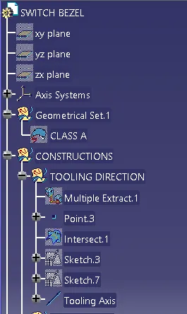
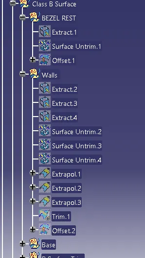
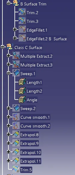
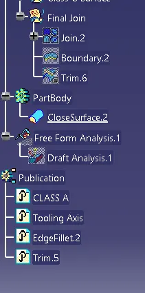
CONCLUSION :
Finally the Class – A, B&C surfaces with the Tooling Direction have been created and Published.