Week 9 - Challenge 2 - Switch Bezel Design
AIM
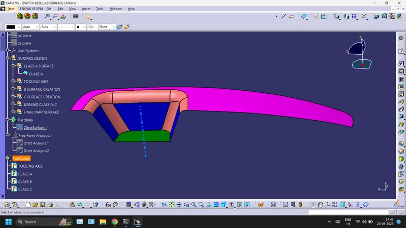
Create the Switch Bezel Plastic component through the given Class-A surface. To begin with, the tooling axis for the given Class-A Surface should be created meeting the requirements of the draft angle and at the end perform the Draft analysis on the model.
CLASS A SURFACE
TOOLING AXIS CREATION
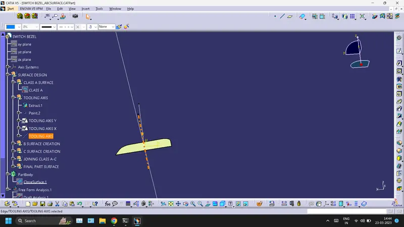
- Create an intersection of CLASS A surface with ZX plane and ZY plane from the intersection create the tooling axis as shown below.
- Create a bisecting line using the lines shown above.
CLASS B SURFACE
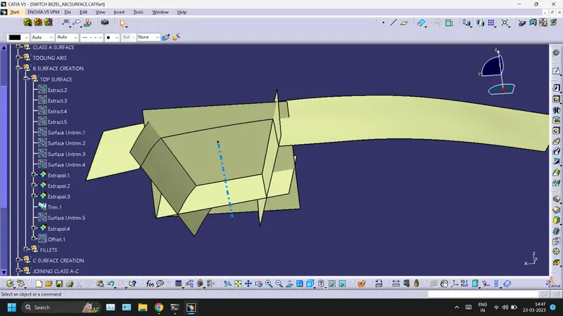
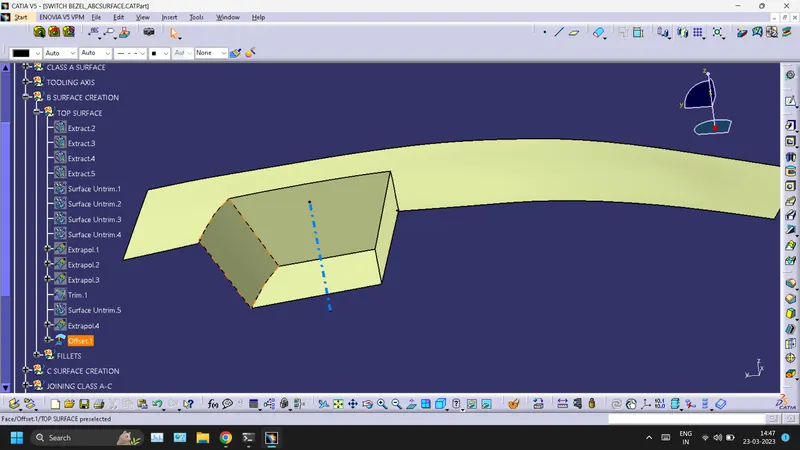
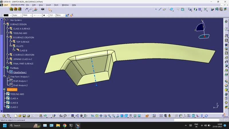
CLASS C SURFACE
- For creating this surface we have extracted the boundry of Class A using multi-extract and then converted to smooth curve. Now this smooth curve is swept along the draft direction with a 3deg draft.
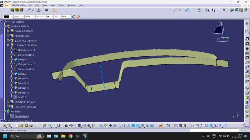
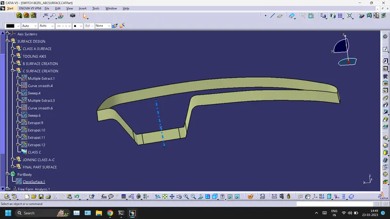
FINAL SURFACE WITH A, B, AND C SURFACE
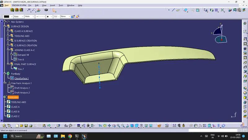
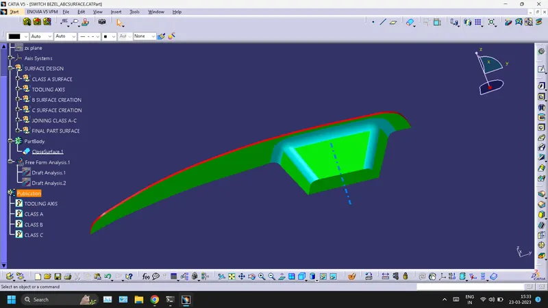
PART BODY OF BASE BRACKET (CLOSED SURFACE)
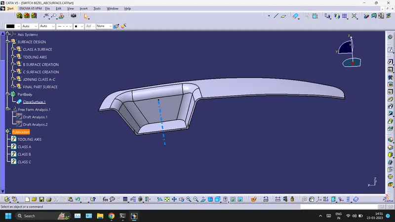
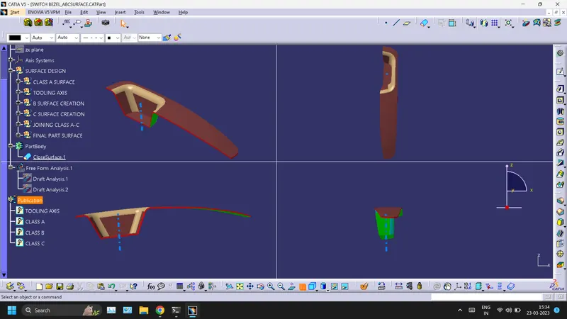
Isometric, Front, Side, and Top View
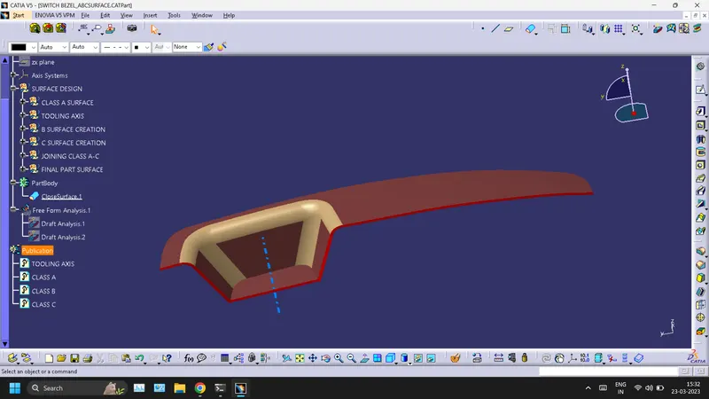
DRAFT ANALYSIS
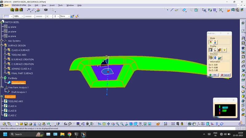
- A-SURFACE
The analysis is done for the 3degree draft. So as can be seen all the surfaces are more than 3deg.
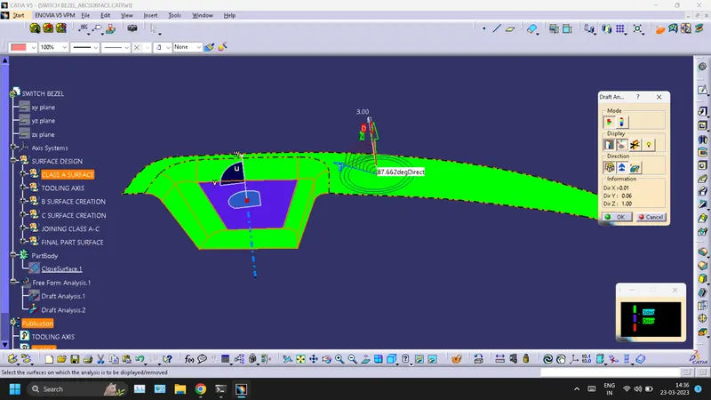
- BASE BRACKET FULL BODY
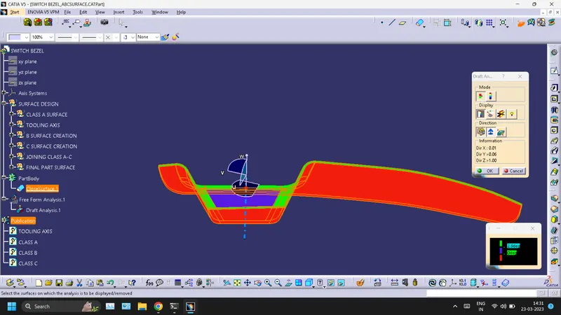
For this analysis, the main tooling axis is taken draft reference.
The following results were obtained