Week 9 Challenge
Q:-Calculate the wave load on the bridge superstructure shown in fig. The maximum crest elevation for the wave is 3 m. The deck of the slab is supported by three I Girders. Each I Girder is 1.7 m height with a top and bottom flange width of 2.5m. The thickness of flange and web is 500 mm The Span of the bridge is 12 m. The width of deck slab is 9m and the thickness of deck slab is 2m. Assume constant r as 5. Assume Cva as 3. The Storm elevation is 8.5m. Take Cr as 0.4
Solution:-
Aim: To calculate the Wave Load on the given bridge and model the bridge in STAAD pro and Analysis the bridge to the Results ie. Bending Moment , Shear Force and deflection etc.
Introduction:
Wave Loads are caused by disturbance of the water surface. They develop due to wind, boat or ship wakes, or other forces due to under water land sliding due to earthquakes. When wind blow of the sea waves occurs according to the intensity of the wind and generate the force on bridge components like sub structure and super structures
Coastal bridges and sea links are subjected to severe wave loads, especially during extreme conditions such as cyclones. The severity of these incidences ranges from small visible cracks to total collapse of the structure. Observation from recent catastrophic events and model projections indicate that changes to the climate system are taking place at unprecedented rates. Increased number of natural hazards created a stark realization for the bridge engineering community regarding the vulnerability of bridges under extreme wave loading. Severe damage due to wave loading on offshore and coastal bridges is one of the most alarming concerns for bridge owners and engineers. Recent events of hurricanes and tsunamis prompted researchers and practitioners to advance the bridge design methods to withstand storm wave attacks and avoid the consequences which often are catastrophic. One major challenge in designing a coastal bridge is the evaluation of design forces due to the waves. Several studies have been done in the past outlining the methods of calculating the wave loads on bridges experimentally and numerically. This paper provides a systematic review of the existing literature focusing on determination as well as simulation of the various types of wave loadings, namely quasi-static and slamming. This review incorporates the evaluation of wave forces on both bridge substructure and superstructure subjected to partial submersion as well as complete inundation. Also, an investigation of the changes in wave loading due to variation in the cross section of bridge piers based on the Canadian Highway Bridge Design Code is presented.
Procedure:
Given Data:-
Maximum crest elevation = 3 m
Span of the bridge = 12 m
No of Girders = 3 Nos
Height of the girder = 1.7 m
Bottom width of flange = 2.5 m
Thickness of flange and web= 500 mm
Maximum crest (η max) = 3 m
No of Girders (N) = 3
r = 5
C va= 3
Cr= 0.4
Δ Z h = η max – Centroid of the I-girder
= 3-(1.7/2)= 2.15 m
Δ Z v = η max –Elevation of bottom deck
3-1 = 2 m
Vertical Load Fv = r x Δ Z v x Av
= 5x2x (9x1.7/2) =76.5 KN
Horizontal Load = r x Δ Z h x Ah
5x2.15x12x1.5= 193.5 KN
Maximum Vertical Load (Fv max) = Cva x Fv
3x 76.5= 229.5 KN say 230 KN
Maximum Horizontal Load (Fh max) = (1+Cr(N-1) x Cva x Fh
= (1+0.4(3-1) x 3x193.5=1044.9 say 1055 KN
We need to model the bridge in the STAAD.pro as per given data
Step-1
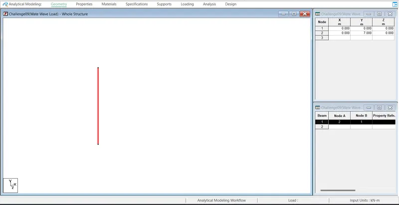
Create two nodes with Coordinates (0,0,0) and (0,7,0) respectively and add the beam
Step-2
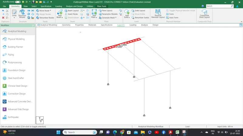
1) Model the 2 nos of piers with spacing of 5 m for piers through transilation repeat and connect the two colums for pier cap with cantilever
2) create the pier -2 at the distance of the 12 m through transilation repeat.
3) make three main beam(girder) through the connect the two nodes which are created the nodes two beams as shown in the above fig.
4) creat a mess 0.5 m X0.5 through trasalation repeat for the slab over the beam for the span of 12 m
5) Assign the fixed support for all colums.
Step-3
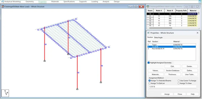
Define and assign circular section having 1.5 m dia for column as shown fig
Step-4
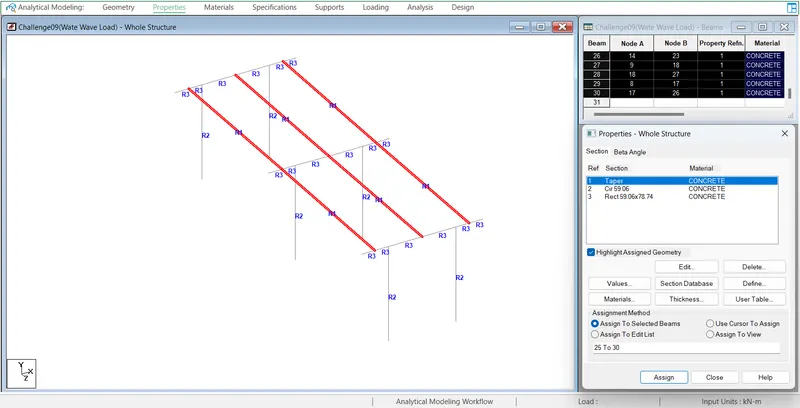
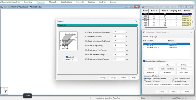
Define and assign the Taper beam the properties as below
Depth of the beam= 1.7 m
thickness of web = 0.5 m
Top flange width= 2.5 m
bottom flange width= 2.5 m
Top flange thickness = 0.5 m
bottom flange thickness= 0.5 m
Step- 5
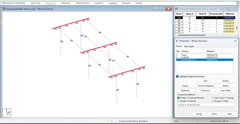
Define and assign rectangular 0.3 m X 1.5 m for the cross girder as shown in fig
Step-6
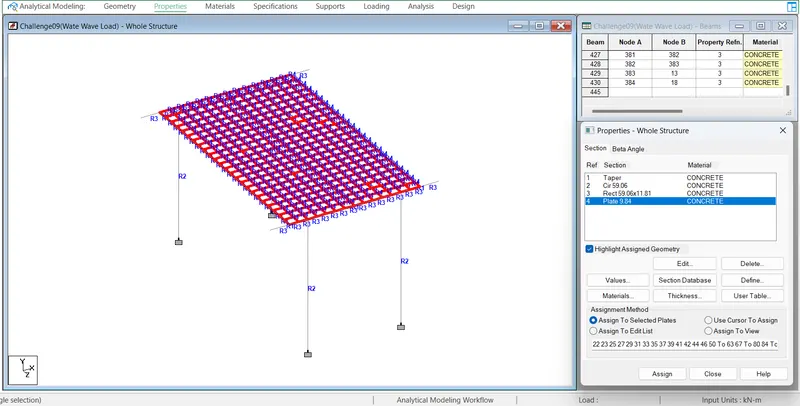
Define and assign the plate with thickness of 0.250 m as shown fig above.
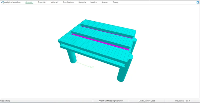
3D View of the Bridge
Step-7
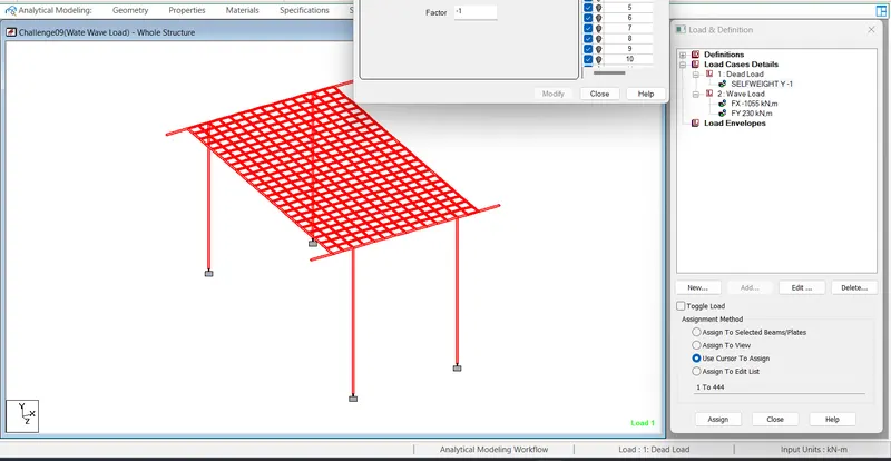
Loading
Go to Load case details add DL , assign the self weight factor -1 for entire the structure
Step-8
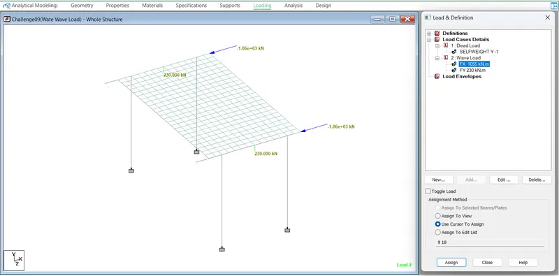
Add Wave load in the load cases and define nodal load both Maximum Horizantal load (1055 KN ) in the direction -ve direction of Z
and Maximum Vertical Load (230 KN) in the y-direction below
Step-9
Check
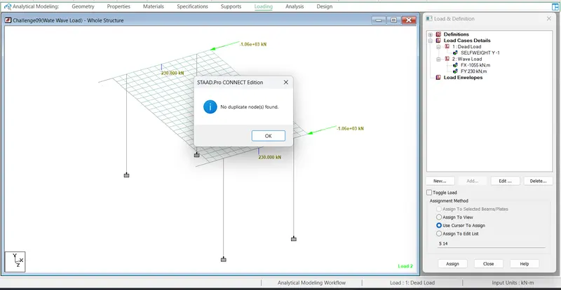
Duplicate node check
No duplicate node found
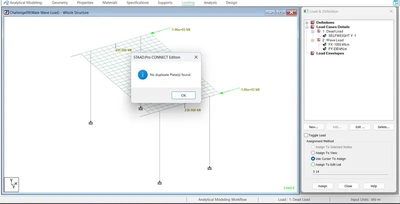
No duplicate plates found
Step-10
Analysis and Design
Analysis command
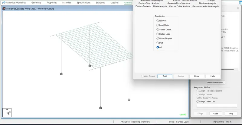
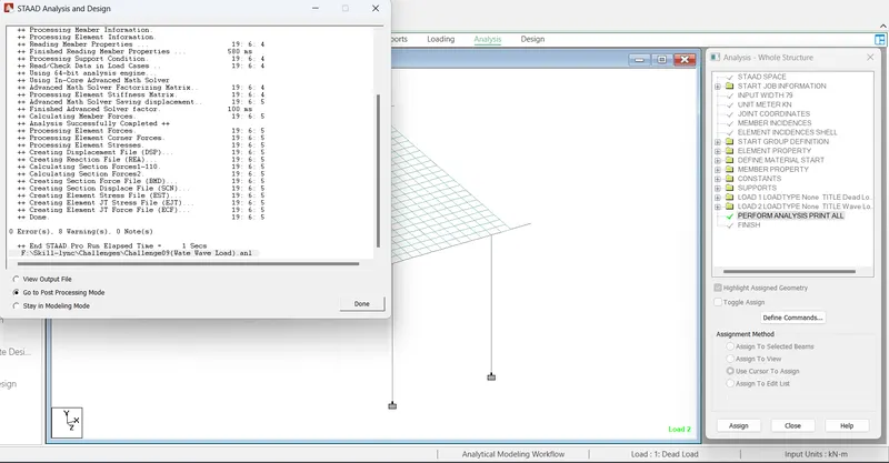
Analysis has been done with Zero errors as shown below
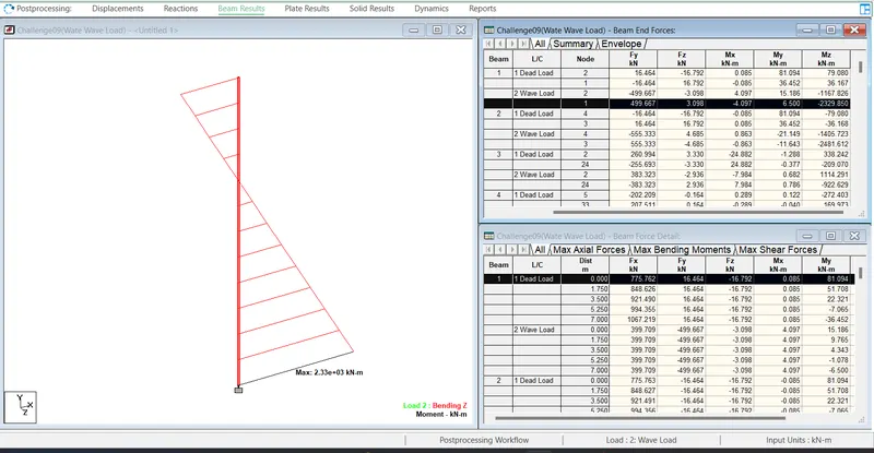
Results
Maximum Bending Moment in the pier is 2329.850 KN-m
Supports reactions of the pier
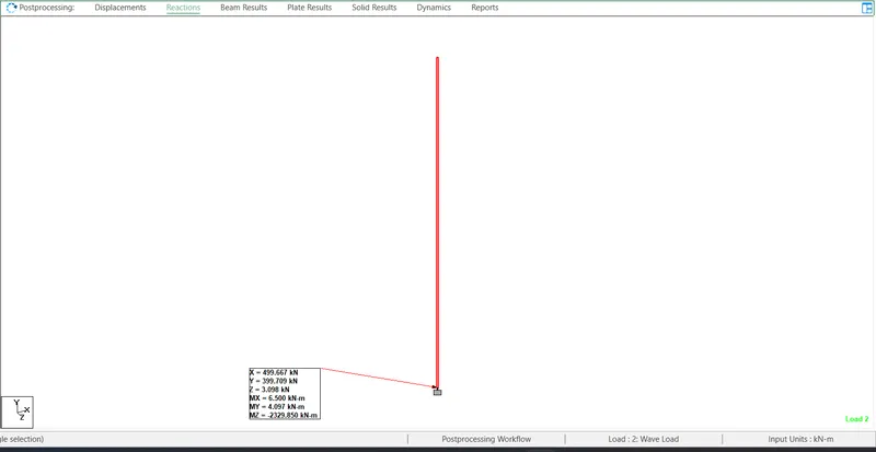
Fx = 499.66 KN
Fy = 399.709 KN
Fz = 3.098 KN
Mx = 6.5 KN-m
My = 4.09 KN-m
Mz = 2329 KN-m due to horizantal wave load
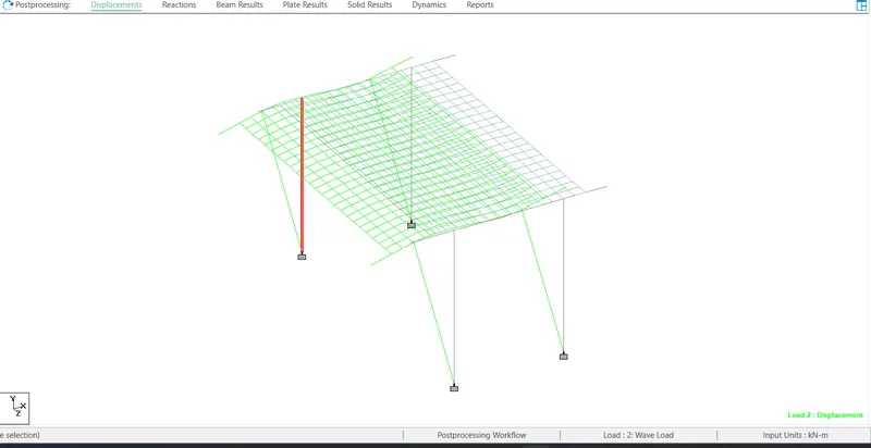
Deflecton
Maximum deflection = -1.59 mm
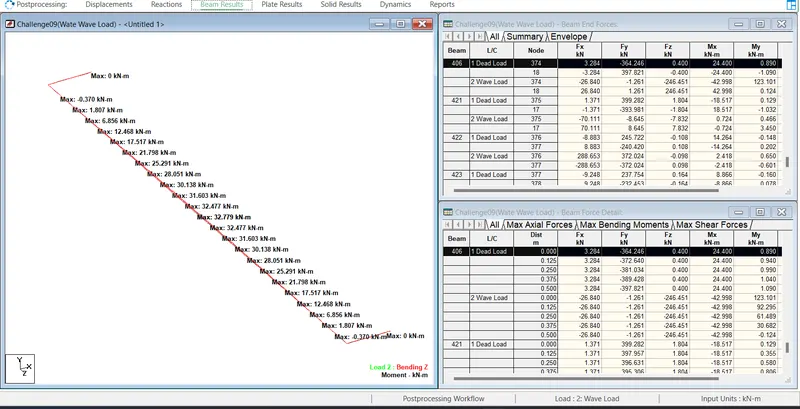
Maximum Bending of the Longitudinal Girder = 32.7 KN-m
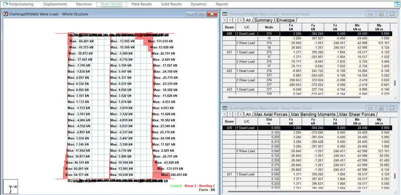
Maximum Shear Force in Main Beam = 246.451 KN
Results
Maximum Bending Moment in the pier is 2329.850 KN-m
Fx = 499.66 KN
Fy = 399.709 KN
Fz = 3.098 KN
Mx = 6.5 KN-m
My = 4.09 KN-m
Mz = 2329 KN-m due to horizantal wave load
Deflecton
Maximum deflection = -1.59 mm
Maximum Bending of the Longitudinal Girder = 32.7 KN-m
Maximum Shear Force in Main Beam = 246.451 KN
****************END*********************
Thank you