Week 4 Challenge
AIM: Design of Abutment wall length of 5 m for 7 m soil filling and founding level is at 3 m below gorund Level water table at gound level as per assumption.
INTRODUCTION: Earth pressure is a horizantal load on the wall due to eath fill behind the wall.There are three condtions are follows
1) Active Earth pressure
2) Passive Earth pressure
3) Earth pressure at rest.
Given data
A) Length of Abutment wall = 5 m
B) Height of Abutment wall= 7.5m assumed from the top of foundation.
C) Ground level is at 3 m above foundation top
D) Height of back fill is 7 m above foundation top.
E) Wall thickness assumed 500 mm
F) Assume density of soil =18 KN/m3
G) Denisty of water = 10 KN/m3
PROCEDURE:-
Earth pressure calculation
Earth pressure= Density of soil X Height of earth fill
Ep=(ɣ X H)
Earth pressure due to 7 m earh fill
Ep1= 18X7=126 KN/m2
Earth pressure on the wall due 3 m earh fill another side of the wall
Water table is at Ground level
| ɣ w = 10 KN/m3 |
Earth Pressure due to 3 m ht
| Ep=(ɣ-ɣ w) H1 |
Ep2=(18-10)X 3= 24 KN/m3
Analysis to be done through STAAD model.
STEP-1
Create node
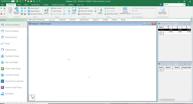
Step-2
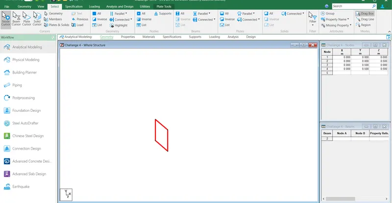
Create a four nodes with help of transilation repeat and add plate.
Step-3
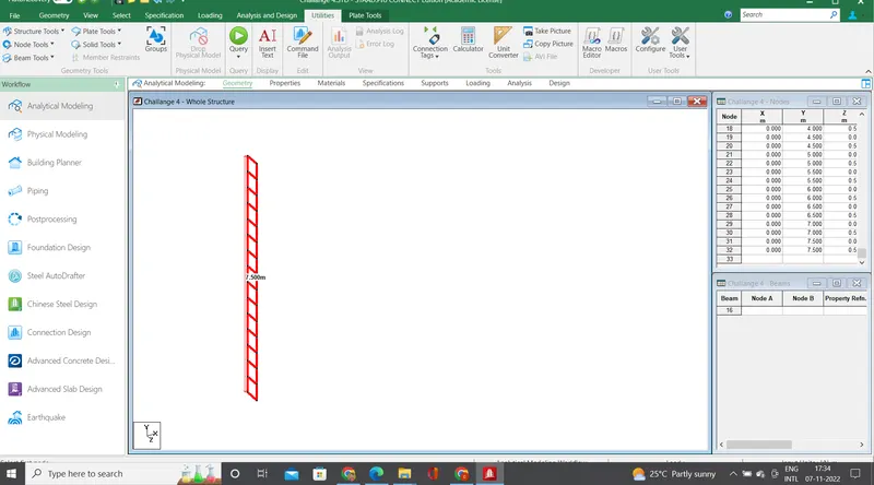
Making 7.5 m ht wall in y-direction through translational repeate with 0.5 m mess.
Step-4
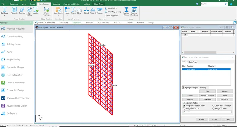
Model the 5 m length and 7.5 m height with 0.5 mX0.5m mess through translation repeat
Step-5
Add fixed support at the bottom of the wall as a end condition.
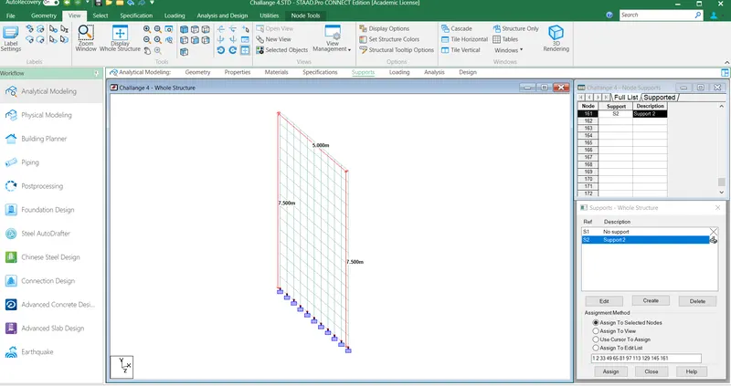
Step-6
3 D view of the wall with 0.5 m thick.
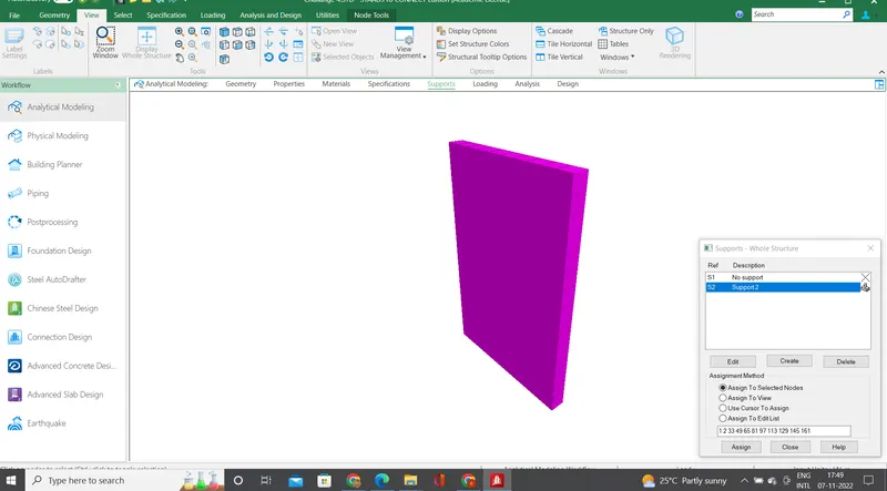
Step-7
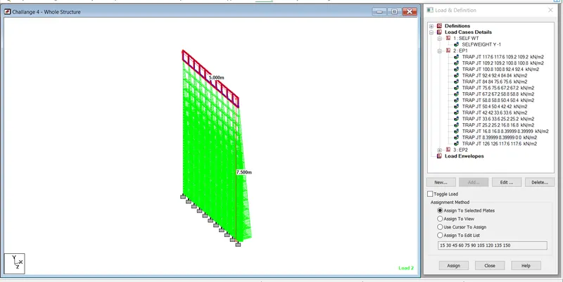
Apply the Earth pressure load(EP1) up to 7 m height which has calculated above through hyostatic loads as shown in the fig on 0.5 m width of wall element.
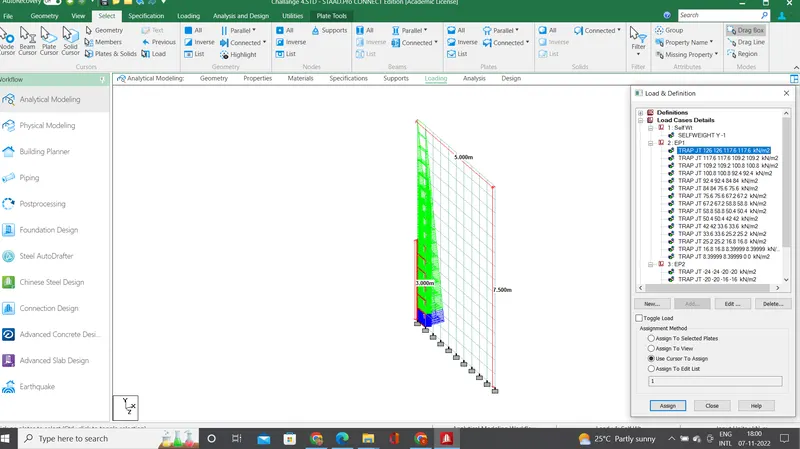
Step-8
Apply the load on overal width of wall in particular ht.
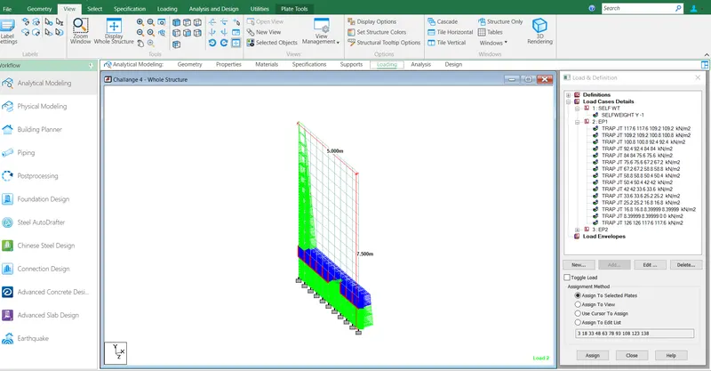
Step-9
Apply the all EP1 load on entire wall through hydrostatic loads as shown in the fig
Step-10
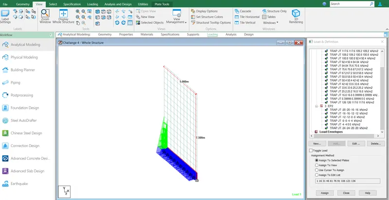
In the same way the Earth Pressure (EP2) another side also up to GL which as calculated above
Step-11
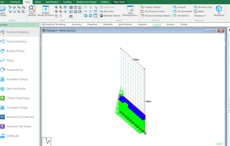
Apply Ep2 to entire wall with width of 5 m up to Ground Level (3 m ht from the bottom of the wall)as shown in the fig below
Step-12
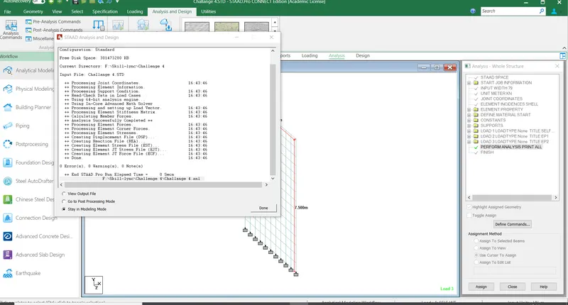
To Analize the model go to Analysis and Design and go for the pre-Analysis command select all and Ok
Click the Run Analysis and got Zero-warning and zero errors.
Step-13
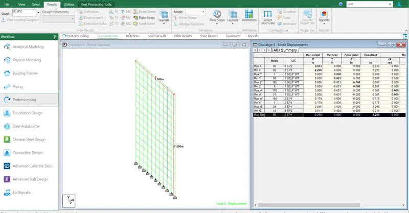
Go to Post and get the results
Displacement at 75 mm
Step-14
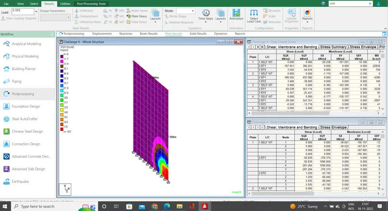
Maximum SF SQ(XY) = 175 KN
Step-15
Maximum Bending Moment 0.061 KN-m/m (MXY Local)
Results
Maximum displacement 75mm at top of the wall
Maximum Shear Force =175 KN
Maximum Bending Moment 0.061 KN-m/m