Week 5 Challenge
Calculate the design wind loads for the bridges to be designed at Mumbai.
- The height of the bridge above ground level is 9 m.
- It is located in open terrain with well scattered obstructions of height less than 10m.
- The pier size is 1.5 x 1.5 m.
- Apply the wind load in Staad.pro
Answer:-
AIM: Design of the Bridge for wind loads which is located at Mumbai with height of 9m from Original Ground Level.
INTRODUCTION:
Wind load is the load (pressure KN/M2 or Kg/Cm2) placed on the exterior structure by wind. Wind Forces and their effects (static and dynamic) that should be considered when designing the buildings, bridges, structures and components thereof. Wind speeds vary randomly both in time and space and assessment of wind loads and response estimation are very important in the design of structures. The detail of this wind load calculation involves important wind characteristics such a Basic wind speed, terrain category modification factors, wind pressure force coefficient..etc information which has given IS 875 part-3.
Given data/Assumed data
- Length of the Bridge = 20 m (2X10 m)
- Height of Bridge= 9 m from the Original Ground Level.
- Foundation depth assumed 2 m from the ground level.
- Pier Size 1.5 m X 1.5m.
- The Bridge is Located in open terrain with well scattered obstruction of height less than 10 m
PROCEDURE:-
Calculation of Wind Pressure
As per IS 875 part -3 2015 clause No 6.3 Design wind speed is mathematically expressed as below
Vz = Vb X k1 X k2 X k3 X k4
Where Vz = Design wind speed at height z, in m/s
Vb Basic wind Speed of Mumbai = 44 m/s as wind map.
K1= Probability factor risk coefficient (clause 6.3.1 Table-1) = 1.07 (Important building and structures)
K2 = Terrain roughness and height factor (clause 6.3.2 Table-2) = 1.00
K3 = Topography factor (clause 6.3.3.1) up wind slope assumed as below 3 degrees
= 1.00
K4 = Importance factor for the cyclonic reason (clause 6.3.4) which shall be considered within 60 KM radius from costal area (Mumbai is in that region)
The Bridge can be considered structures of post cyclone for emergency services
= 1.3
Design wind speed (Vz) = Vb x k1xk2xk3xk4
= 44X1.07X1X1X1.3 = 61.204 m/sec
As per IS 875 part-3 clause 7.2 the Design wind pressure is Pz
Pz=0.6 VzXVz
= 0.6 X 61.204 X 61.204= 2247.55 N/m 2
= 2.247 KN/m 2
- Wind Load on the columns in X direction
Column size is 1.5X1.5 (as per data given).
Member Load = 2.247X1.5=3.370 KN/m
- Wind Load on Cross Beam in X direction
Beam Size is 0.5X0.9
Member Load is 2.247X0.9= 2.022 KN/m
- Wind Load in Z direction.
Load on Column
Member Load is 2.247X1.5= 3.370 KN/m
- Load on Main beam is 2.247X1.2= 2.696 KN/m
STAAD ANALYSIS
Step 1. Creat a node and creat a beam of 11 m in Y-direction
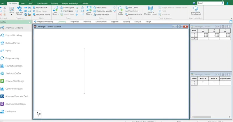
Step 2. Creat 4 Columns in Z direction with the help of Translation repeat C/C distance of 3 m.
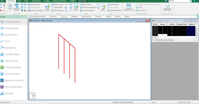
Step 3. The set of the colums to made another 2 sets through translation repeat with link steps and open basein the spacing of 10 m
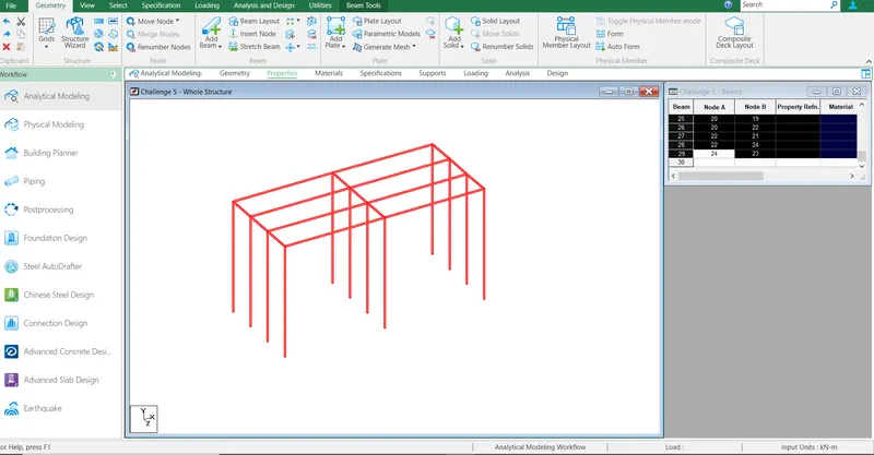
Step 4. Define a required supports (fixed) and Foudation for the bridge.
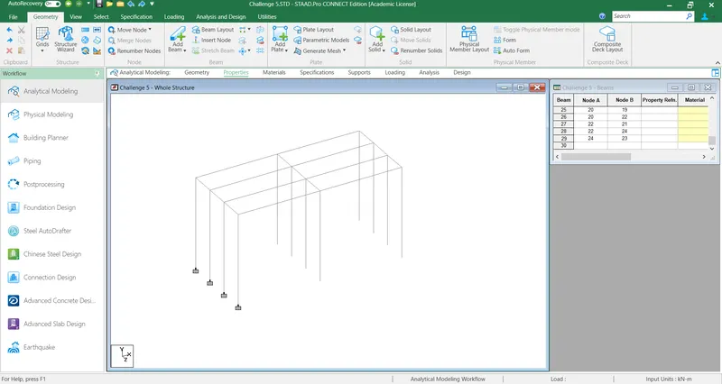
Step 5. Define and assign the properties for every member both cloumn and beam, 1.5mX1.5m for column as per data given,0.9X1.2 rectanular section assigned for Longitudinal beam and 0.5X0.9 for Cross beams.
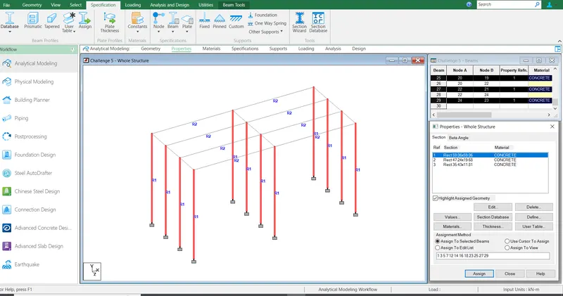
Step 6. Three dimension view of the model
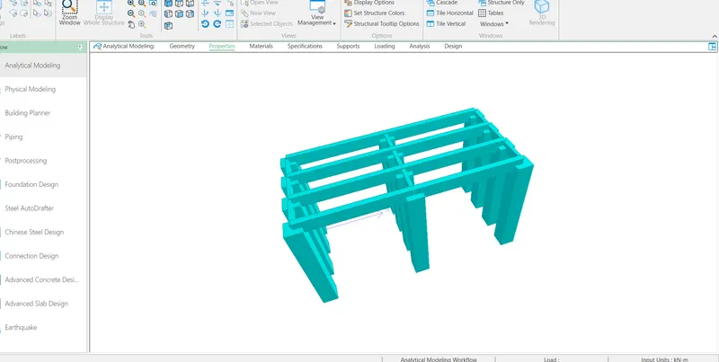
Step 7. Making a mess of 0.5mX0.5m for deck slab with help of translation repeat each panel.
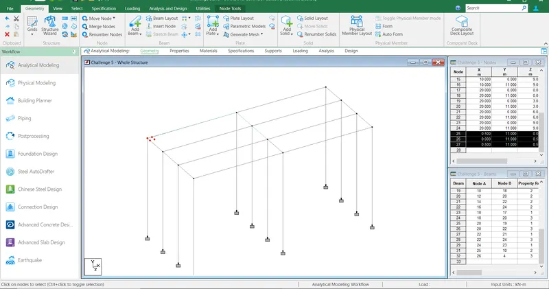
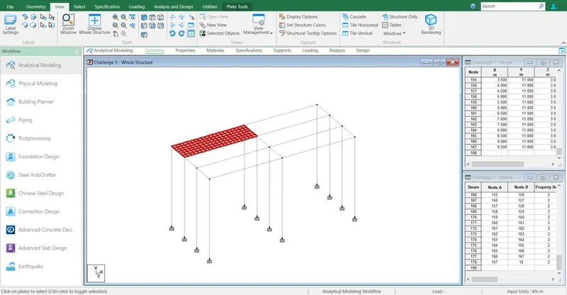
Step 8.Three dinemsion of the model with deck slab with thickness of 225 mm
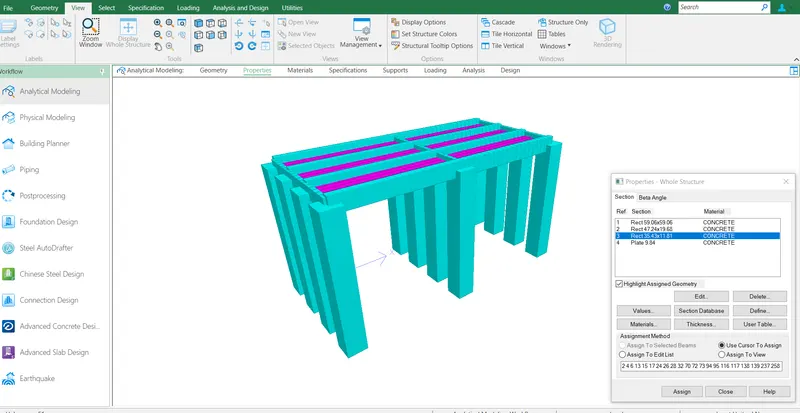
Step 9.Create mess for foundation also with thickness of 0.75 m as shown below
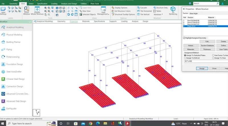
Step 10. Wind load calculation
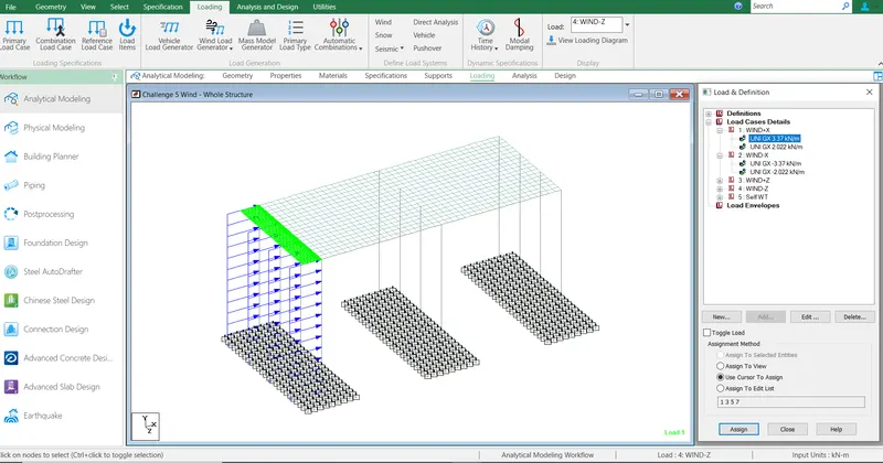
- Wind Load on the columns in X direction
Column size is 1.5X1.5 (as per data given).
Member Load = 2.247X1.5=3.370 KN/m
- Wind Load on Cross Beam in X direction
Cross Beam Size is 0.5X0.9
Member Load is 2.247X0.9= 2.022 KN/m
Add the loads in the STAAD model
WIND+X load apply in X-direction
WIND-X load apply in -X-direction
WIND+Z load apply in Z -direction
WIND-Z load apply in -Z-direction
as shown below
Step 11
- Wind Load in Z direction.
Load on Column Member Load is 2.247X1.5= 3.370 KN/m
- Load on Main beam is 2.247X1.2= 2.696 KN/m
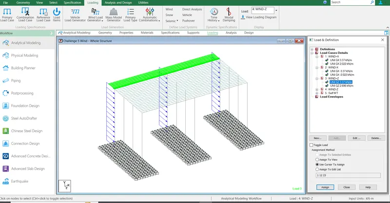
Step 12 After Assigned all loads on respective members
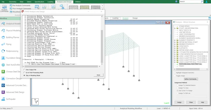
Goto Analysis and Design click the analysis command and all perform analysis
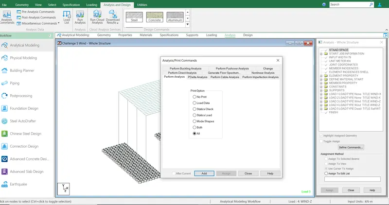
Step 13 after analsis go to post processing mode
Maximum Base pressure got due to Self Weight
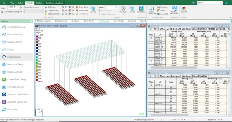
Results
Maximum Base pressure = 106 KN/m2
Minimum Bas pressure = 77 KN/m2
Maximum Bending moment = 324 KN-m
Maximum displacement = 4.722 mm
Maximum SF =187.811 KN