Week 9-Challenge
Objective: 1) To study & generate mesh on given components in HyperWorks.
2) To study connectors & attach the various parts of the given components.
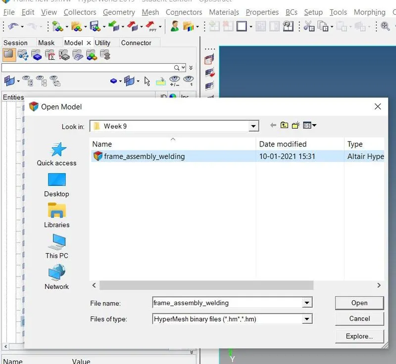
Import the model:
- Selected the open model option in model view.
- Then selected the file and selected open.
2D mesh generation :
- Navigated 2D menu page and selected automesh option

- Selected element size as 5
-
Selected the mesh type as mixed.
- Selected the surface to be meshed
-
Hit the mesh tab.

-
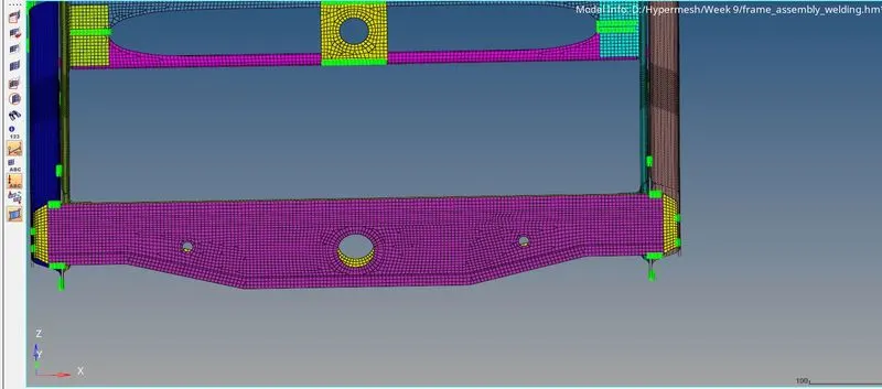
Now, the mesh is generated for all components.
Connectors:
1) Right_Rail_2 & Front_truss_1 :
-
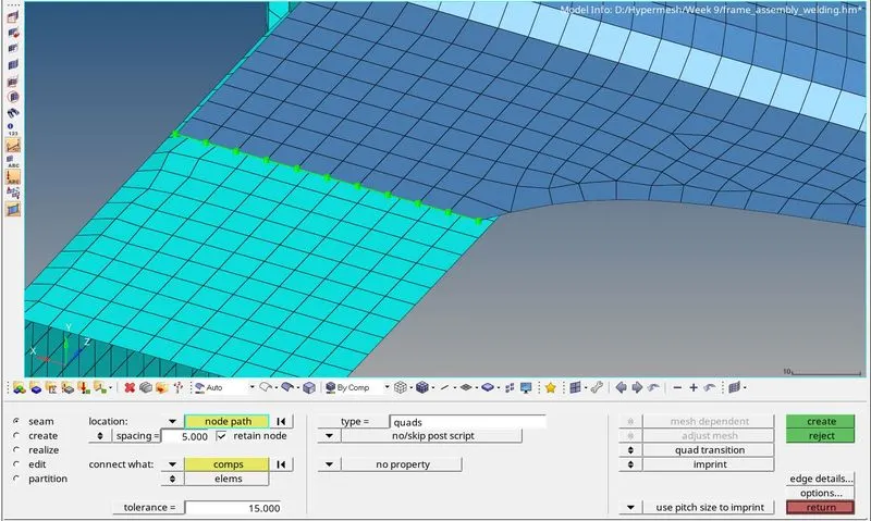
Apply seam quad (angled + capped + L) connector to attach Right_Rail_2 & Front_truss_1
-
Navigated to 2D menu page.
-
Selected the connectors option

- Then clicked seam option

-
For connector location selected nodes by path.
-
Selected components to be connected.
-
Selected the seam weld type as seam quad (angled + capped + L)
-
Defined tolerance as 10.
-
Then hit the create tab.
-
Made sure the connectors are highlighted with green colour.
- That means the connector is realized
2) Left_Rail_2 & Front_truss_1:-
-
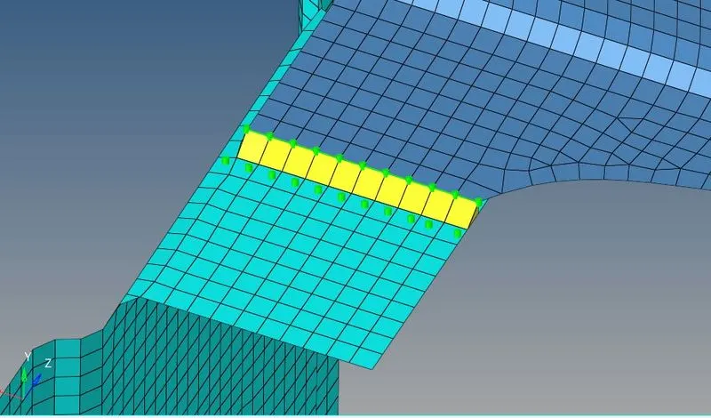
Apply seam quad connector to attach Left_Rail_2 & Front_truss_1
-
Navigated to 2D menu page.
-
Selected the connectors option
-
Then clicked seam option.
- For connector location selected nodes by path
-
Selected components to be connected.
-
Selected the seam weld type as quad
-
Defined tolerance as 10
-
Then hit the create tab.
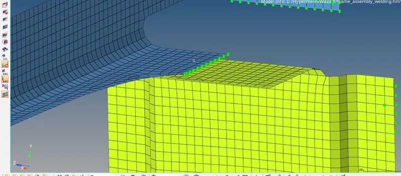
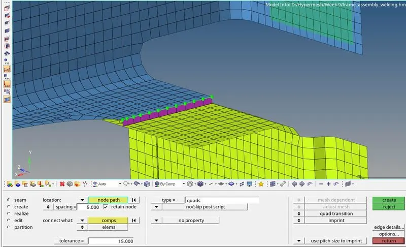
-
Made sure the connectors are highlighted in green colour.
3) Front_truss_2, Front_truss_1 & Right_Rail_1 :
-
Apply spot weld connector to attach Front_truss_2, Front_truss_1 & Right_Rail_1
-
Navigated to 2D menu page.
-
Selected the connectors option
-
Then clicked spot option.

- For connector location selected nodes by path.
-
Selected components to be connected.
- Selected the spot weld type as weld

-
Defined tolerance as 10.
-
Defined diameter as 5 mm
-
Defined number of layers as total 3.
-
Then hit the create tab.
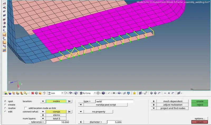
-
Made sure the connectors are highlighted in green colour.
4) Front_truss_2, Front_truss_1 & Left_Rail_1:
-
Apply Hexa (adhesive) connector to attach Front_truss_2, Front_truss_1 & Left_Rail_1
- Navigated to 2D menu page
-
Selected the connectors option
-
Then clicked area option.

-
For connector location selected nodes by path.
- Selected components to be connected
-
Defined tolerance as 10.
-
Then selected the type as adhesive.
-
Then hit the create tab.
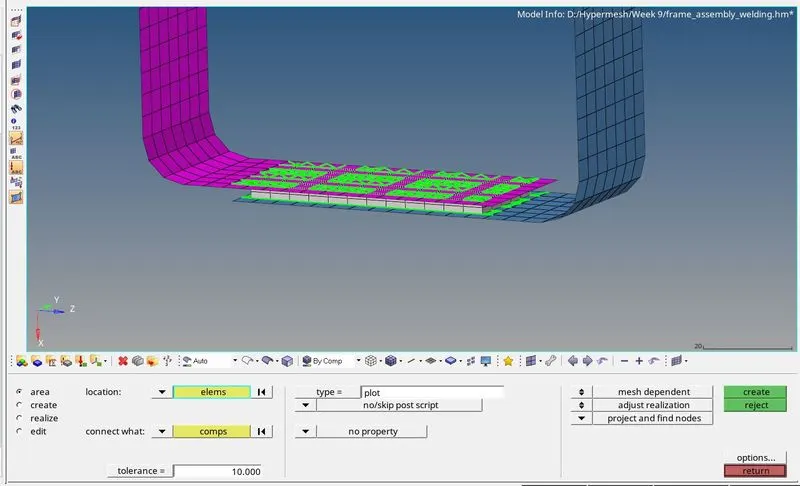
- Made sure the connectors are highlighted in green colour
5)Rear_truss_2 & Right_Rail_2:-
-
Apply Bolt Connector connector to attach Rear_truss_2 & Right_Rail_2
- Navigated to 2D menu page
-
Selected the connectors option
-
Then clicked bolt option.

- For connector location selected nodes by path
-
Selected components to be connected.
- Defined tolerance as 10
-
Then selected the type as bolt (general)
-
Selected create hole option from the dropdown.
-
Then hit the create tab.
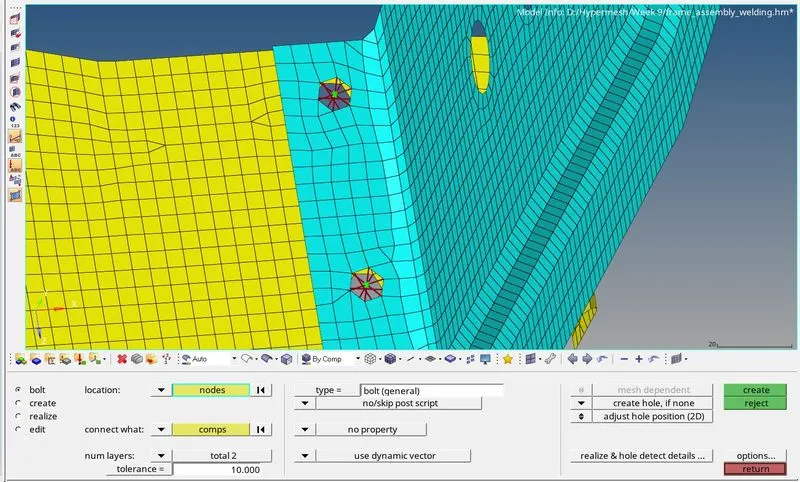
- Made sure the connectors are highlighted in green colour
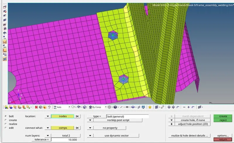
6) Rear_truss_2 & Left_Rail_2:
Repeat same procedure as described for 5) Rear_truss_2 & Right_Rail_2
7) Right_Rail_1 & Right_Rail_2:
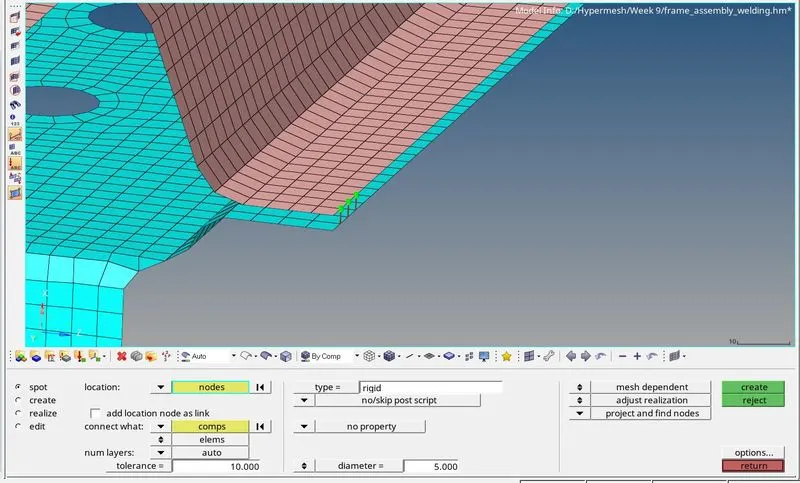
- Apply Spot-weld connector to attach Right_Rail_1 & Right_Rail_2
- Navigated to 2D menu page
-
Selected the connectors option
-
Then clicked spot option.

- For connector location selected nodes by path
-
Selected components to be connected.
-
Defined tolerance as 10.
-
Defined number of layers as auto.
-
Then selected the type as rigid
-
Then hit the create tab.
-
Made sure the connectors are highlighted in green colour.
8) Left_Rail_1 & Left_Rail_2:
-
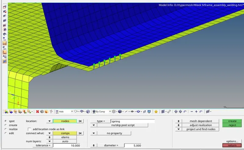
Apply Spot-weld connector to attach Left_Rail_1 & Left_Rail_2
-
Navigated to 2D menu page.
-
Selected the connectors option
- Then clicked spot option
- For connector location selected nodes by path
- Selected components to be connected
-
Defined tolerance as 10.
-
Defined number of layers as auto.
-
Then selected the type as spring
- Then hit the create tab
-
Made sure the connectors are highlighted in green colour.
Conclusion :
- We have successfully created connectors and attached the different components.