Week 6- Challenge
Objective: 1) To study & perform geometry clean up and midsurface extraction on given components in HyperWorks.
2) To Study & perform 2D meshing on a given component.
Import the model:
- Step 1: Selected the import geometry option in the model view
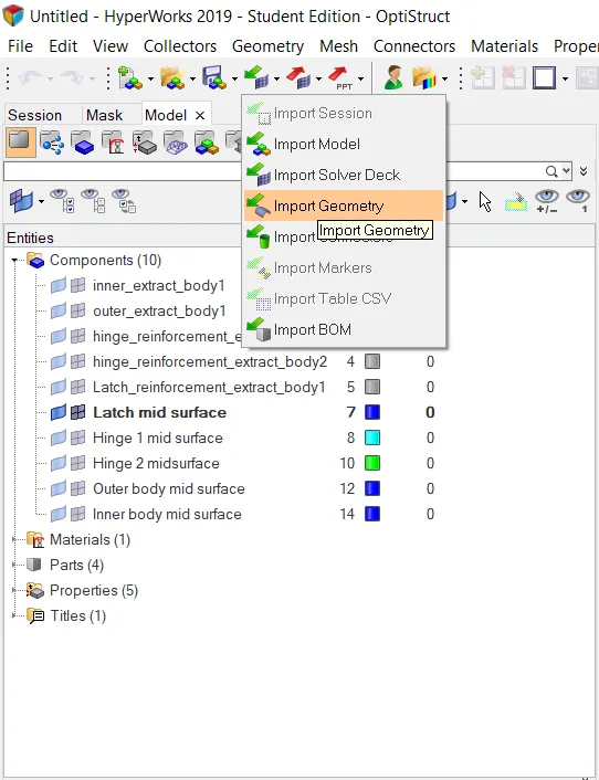
- Step 2: Selected the hood STEP file and selected the import tab.
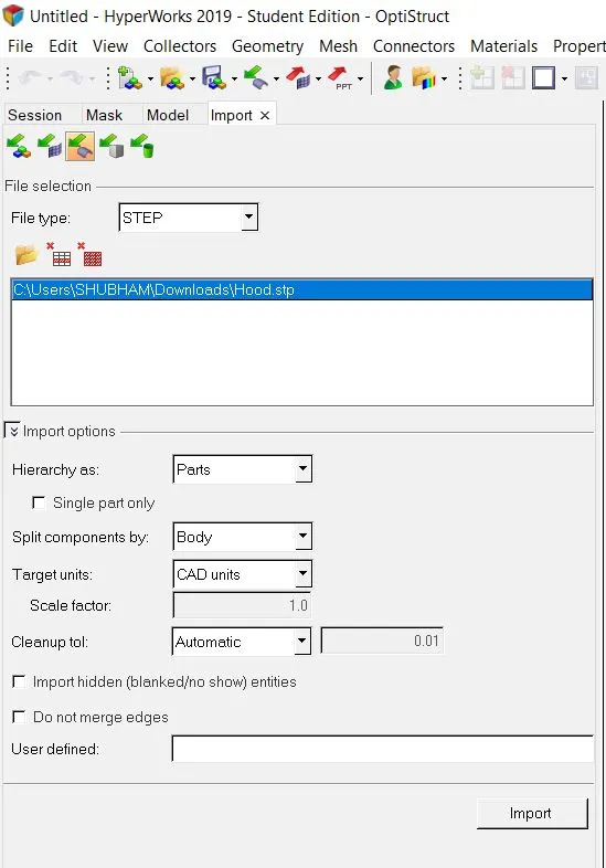
Extract midsurface:
- Step 1:Selected the geometry tools option on the main menu page
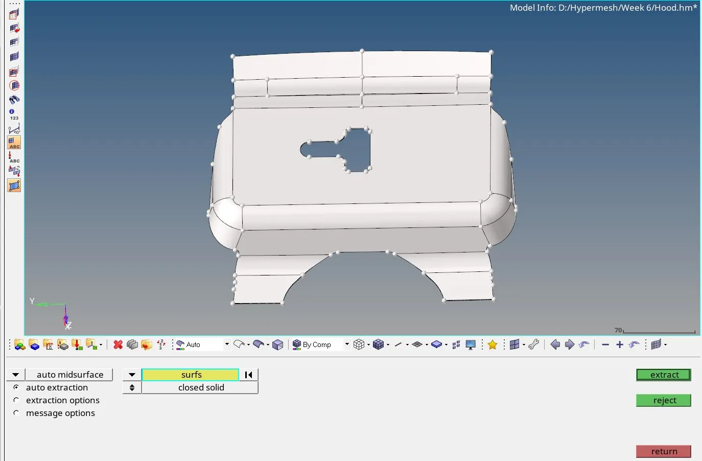
- Step 2:Selected midsurface tool
- Step 3:Selected the surface of the ‘Latch_reinforcement_extract_body’ and selected the extract option and selected skin offset
- Step 4:The midsurface was extracted and renamed it as Latch midsurface
- Step 5:In model view window followed the path as: create > material and a new component was created as Latch midsurface
- Step 6: Navigated to the tool menu page
- Step 7: Selected the extracted midsurface and moved to the newly created component as Latch midsurface.
Repeated the procedure from step 1 to step 4 for the following components:
1) hinge_reinforment_extract_body1
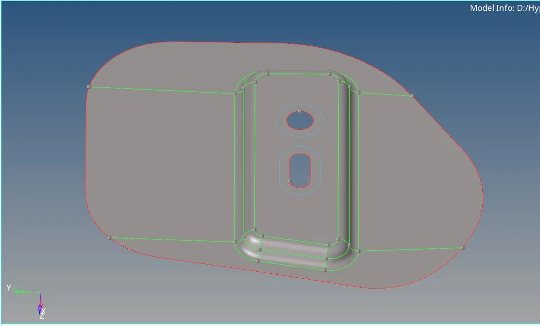
2) hinge_reinforment_extract_body2
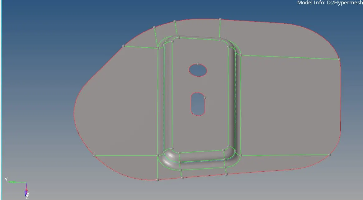
3) inner_extract_body
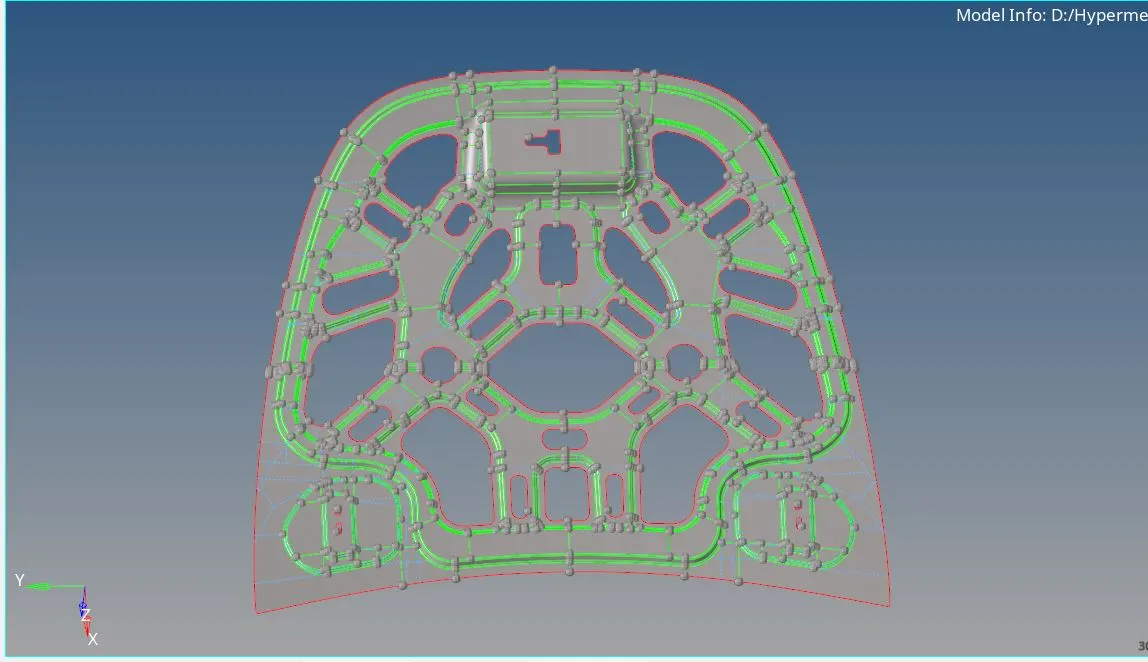
4) outer_extract_body
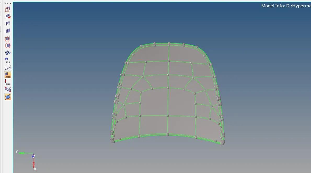
Geometry cleanup
-
Navigated to geometry clean up mode
-
Selected the by Topo option
- This will show the surface irregularities in a model like free edges and missing surfaces
-
Also switched on wireframe mode.
-
That made us find out above errors easily.
-
Navigated to defeature option in geom tools and removed the fillets.
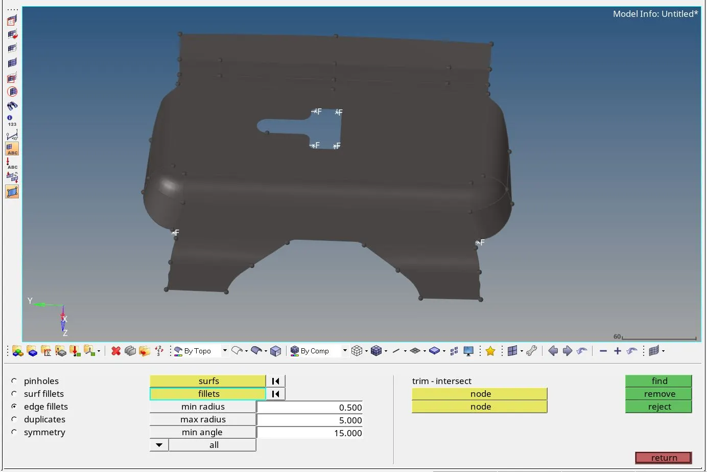
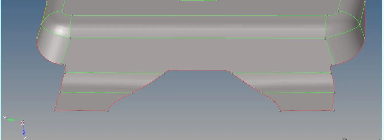
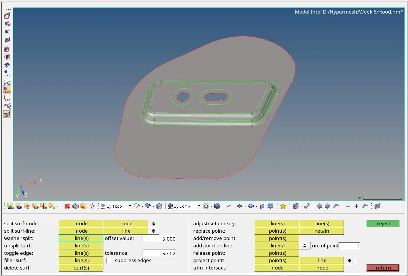
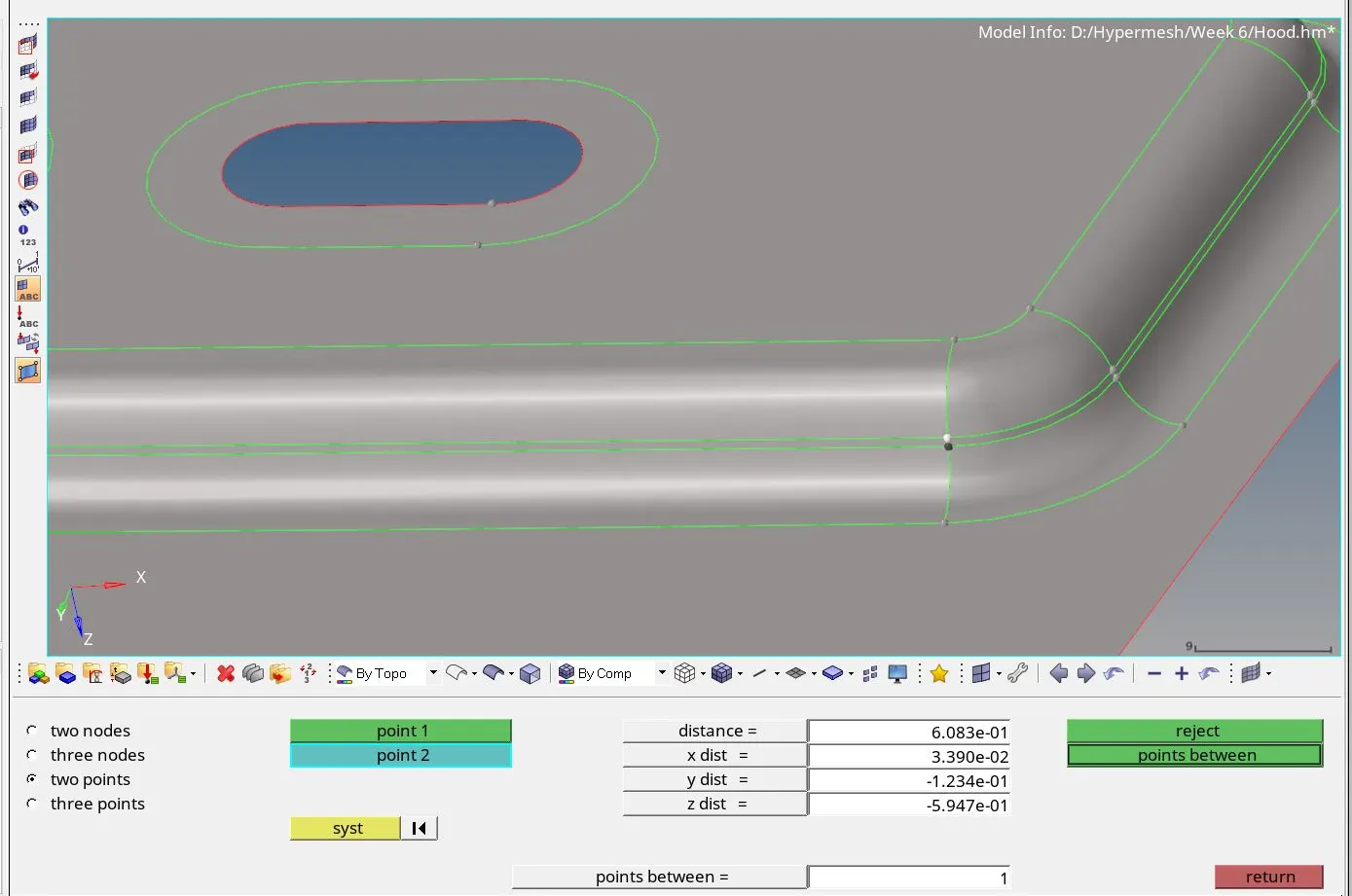
Criteria settings :
-
Navigated to preferences option in the tools bar.
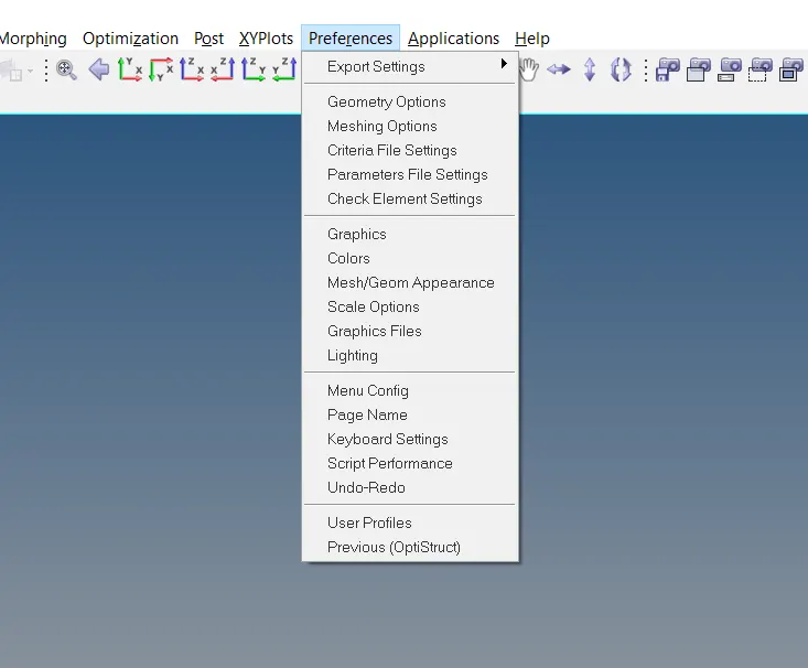
-
Selected criteria file settings from the drop-down list.
-
Assigned criteria as per the requirement mentioned for the model.
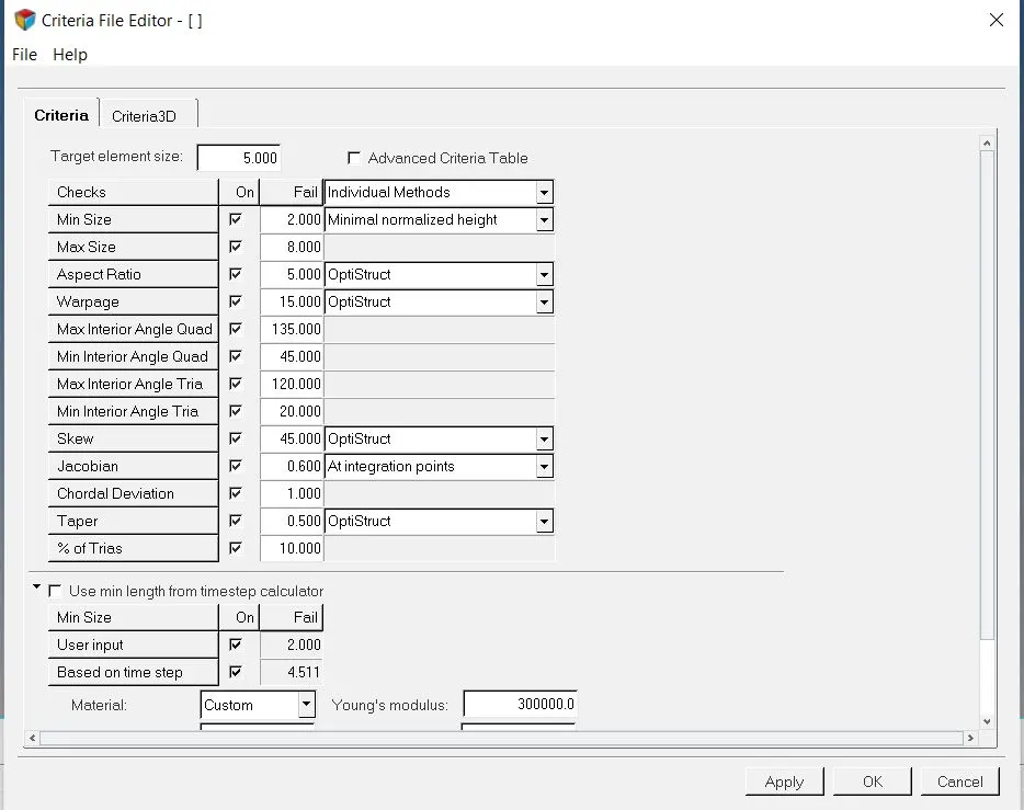
2D meshing :
-
Navigated 2D menu page and selected automesh option
-
Selected element size as 5.
-
Selected the mesh type as mixed.
-
Selected the latch surface to be meshed.
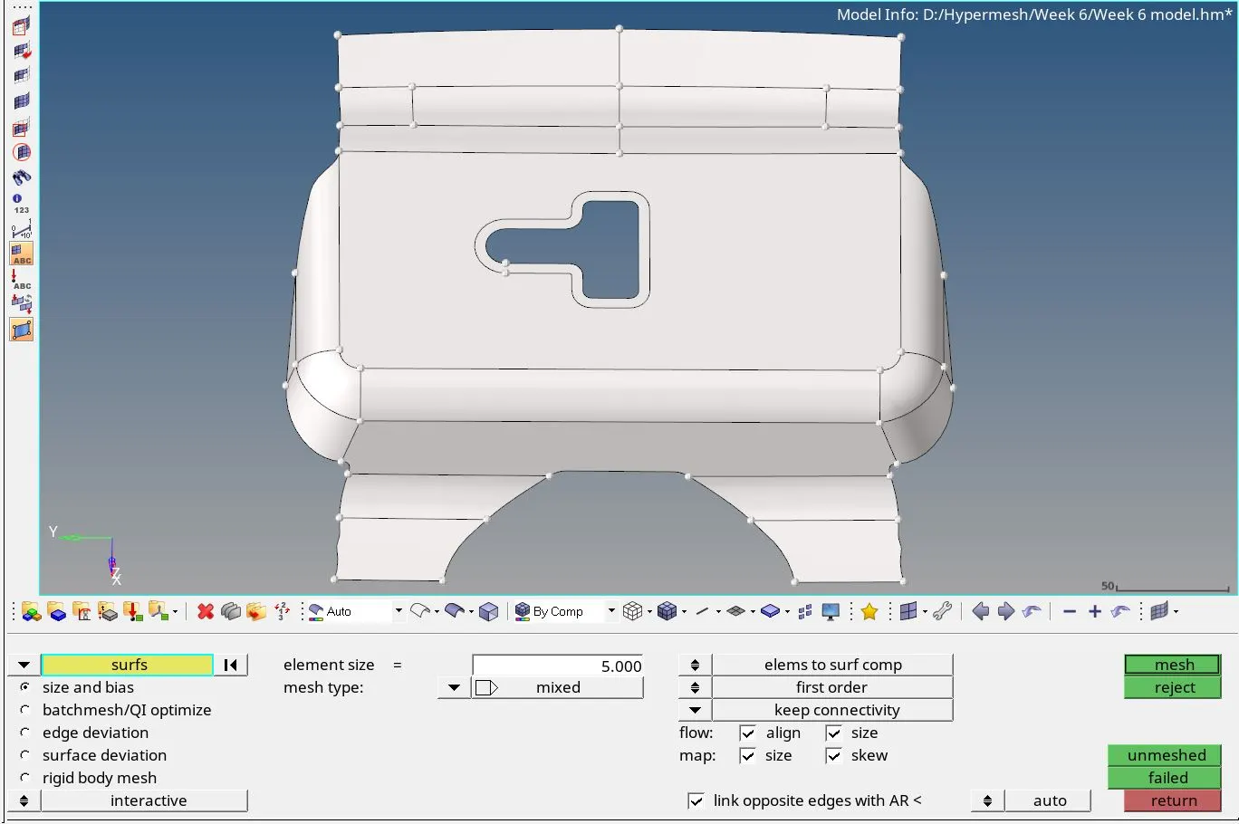
-
Hit the mesh tab.
-
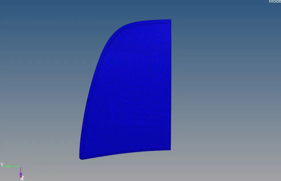
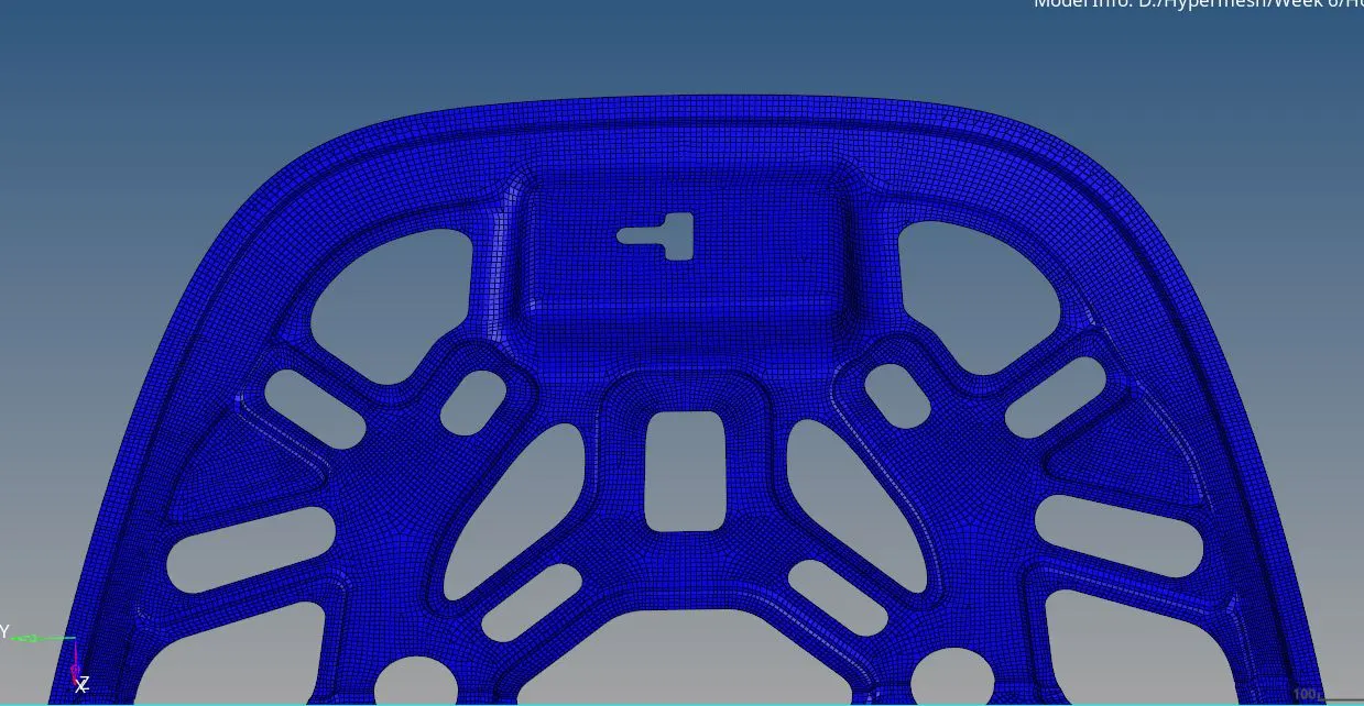
Now the mesh is generated
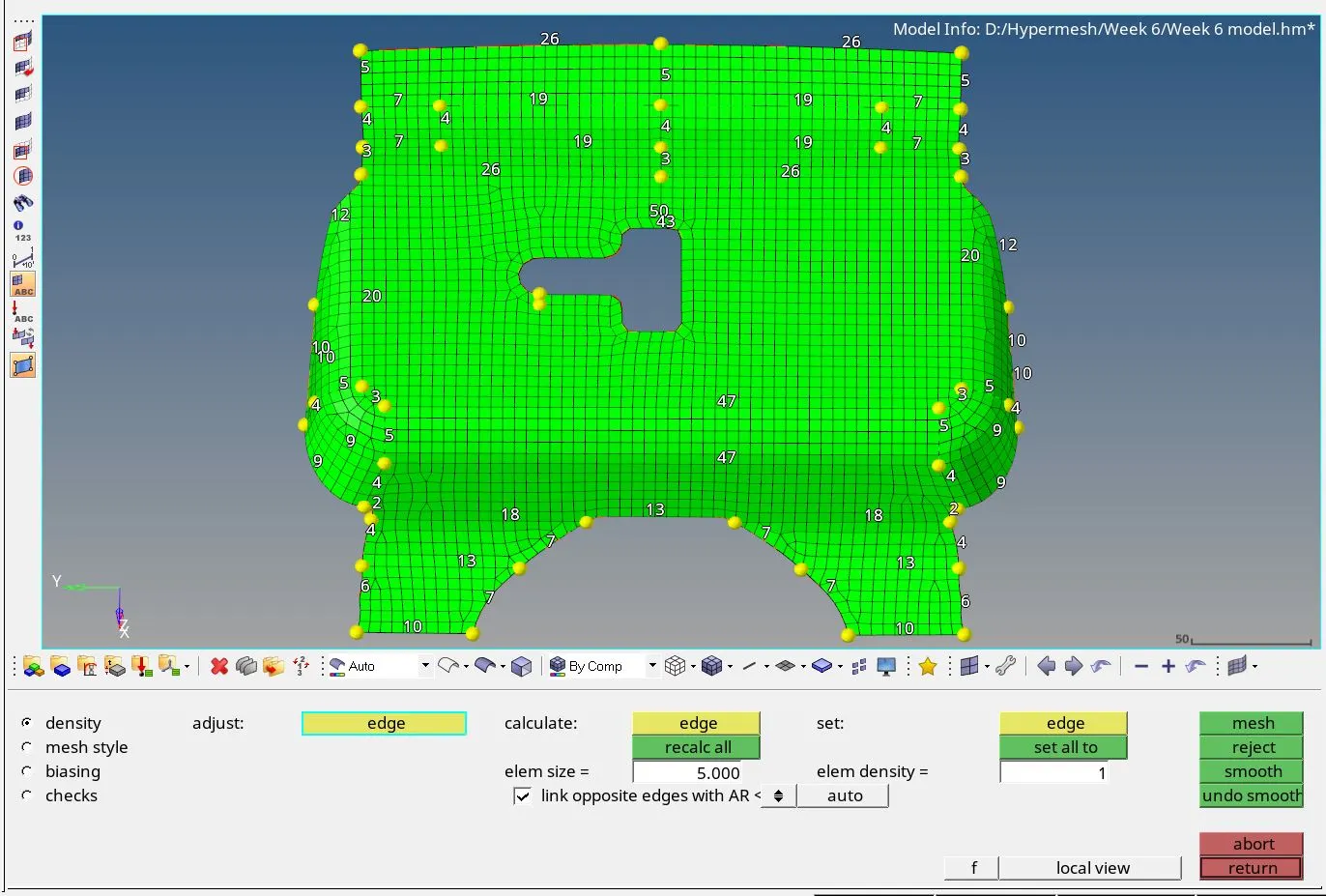
These steps were followed for all components.
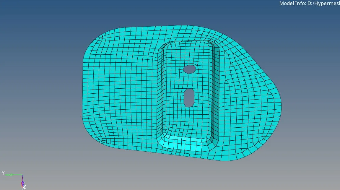
Split surfaces :
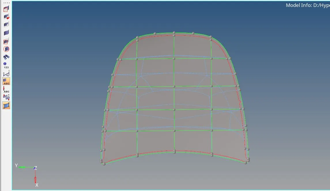
- The inner extract body and outer extract body are lage.
-
-
Thus surface was split into sections to conveniently mesh the large surface.
Check quality index:
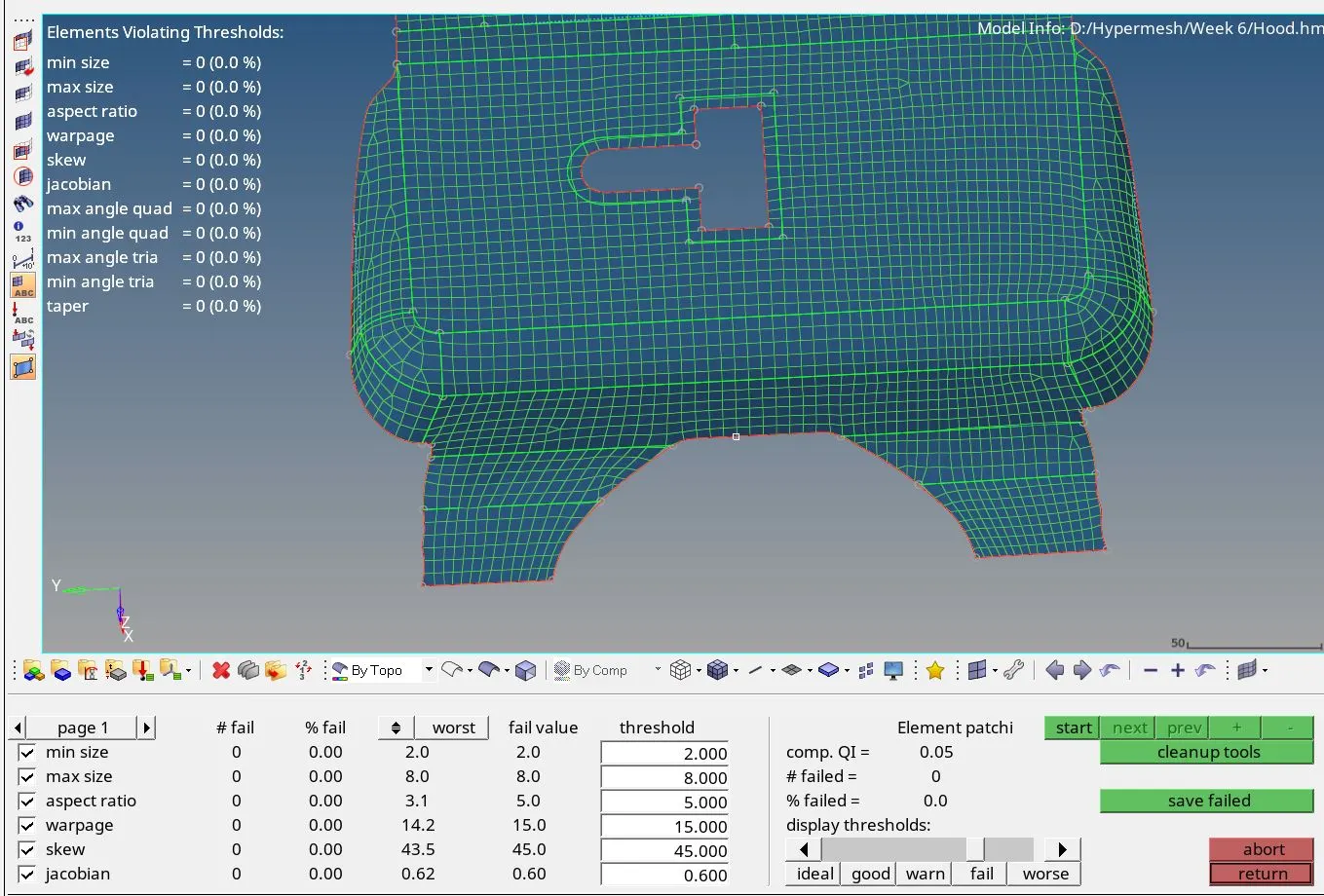
- Navigated to the 2D menu page and selected the quality index option.
-
Now failed elements are visible in yellow and red colour based on the magnitude of error in the elements.
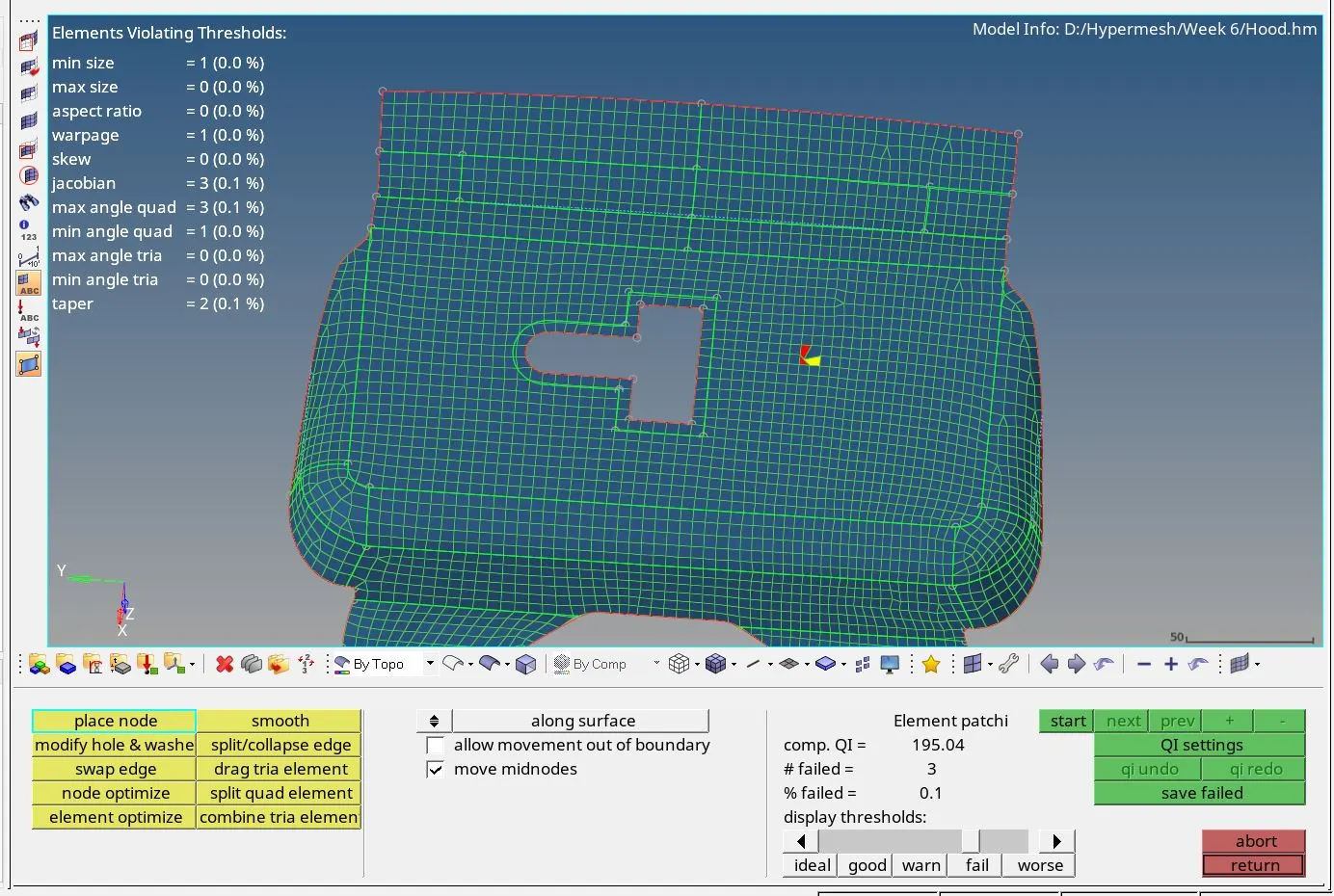
-
Selected cleanup tools to use the respective option to optimize the elements.
-
Following quality checks are considered for obtaining error-free mesh:
- No trias should be touching each other
- No opposite trias should be present in proximity
- No rotating quads
- No trias should be present on feature line and edges.
Check elements:
-
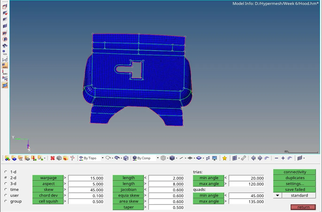
Navigated to the check elements option in the tool menu page.
- Checked each criterion for failed elements
Project nodes:
-
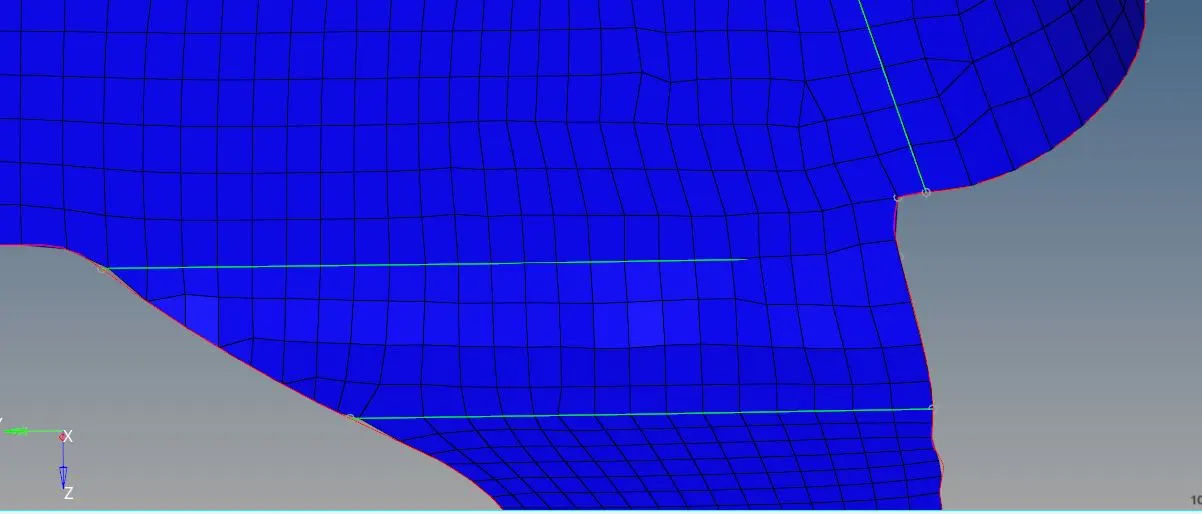
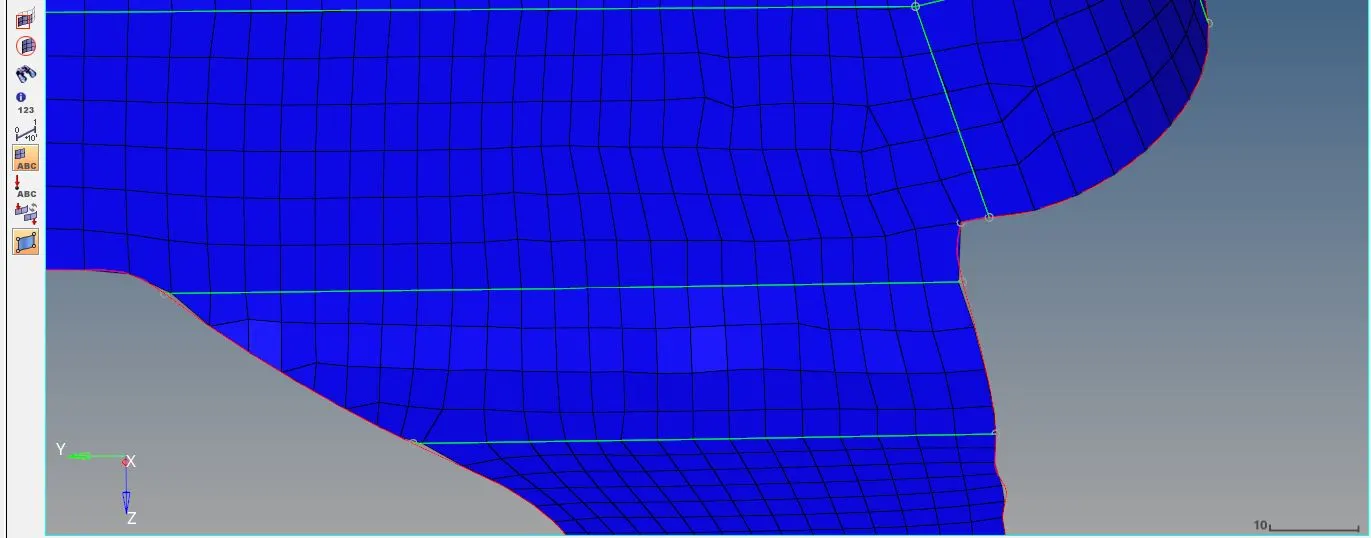
Project nodes option was used to align the elements near the feature line along with it. This will improve mesh flow.
-
Navigated to the tools menu page.
- Selected the project option
- Selected the nodes not aligned with the feature line
-
Selected the feature line that is under consideration.
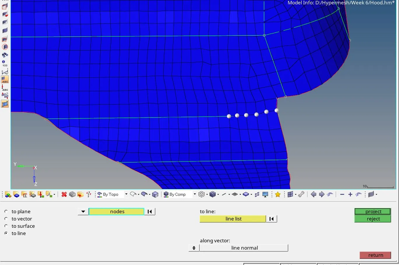
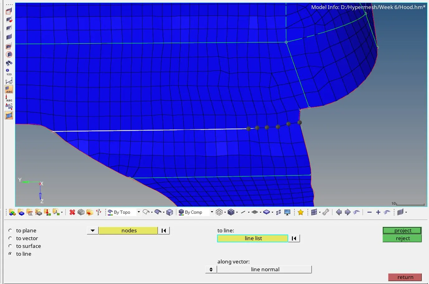
- Hit the project button.
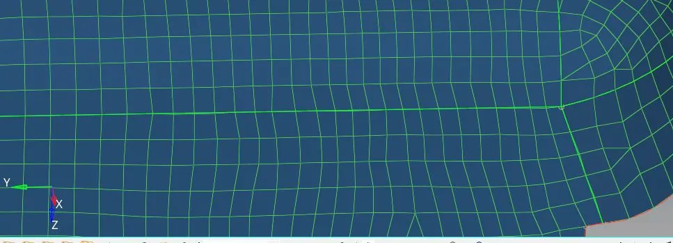
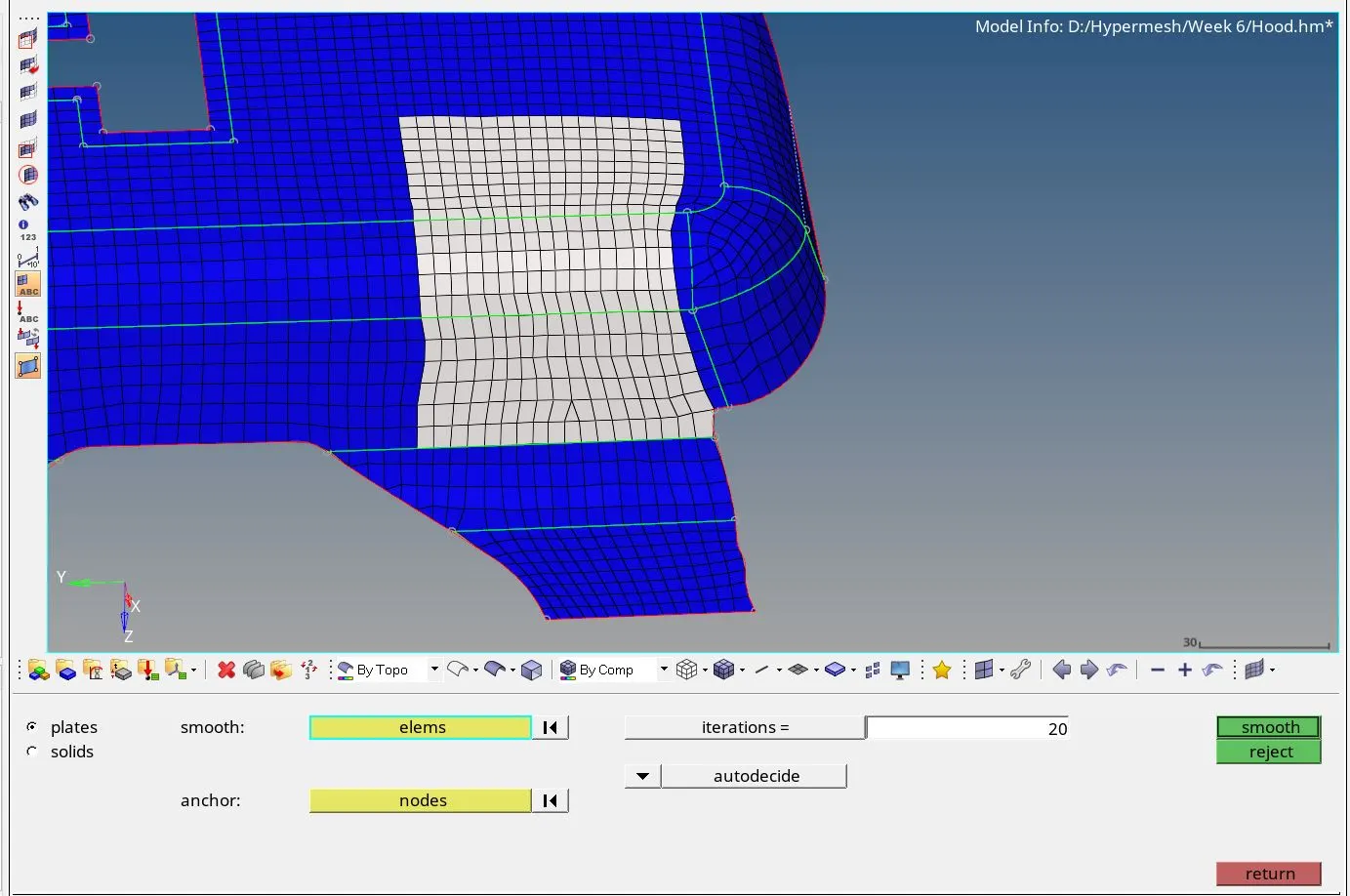
Smooth elements :
-
Navigated to 2D menu page.
-
Selected the elements to be smooth.
-
Set the iteration value.
- Click the smooth button until mesh flow looks good
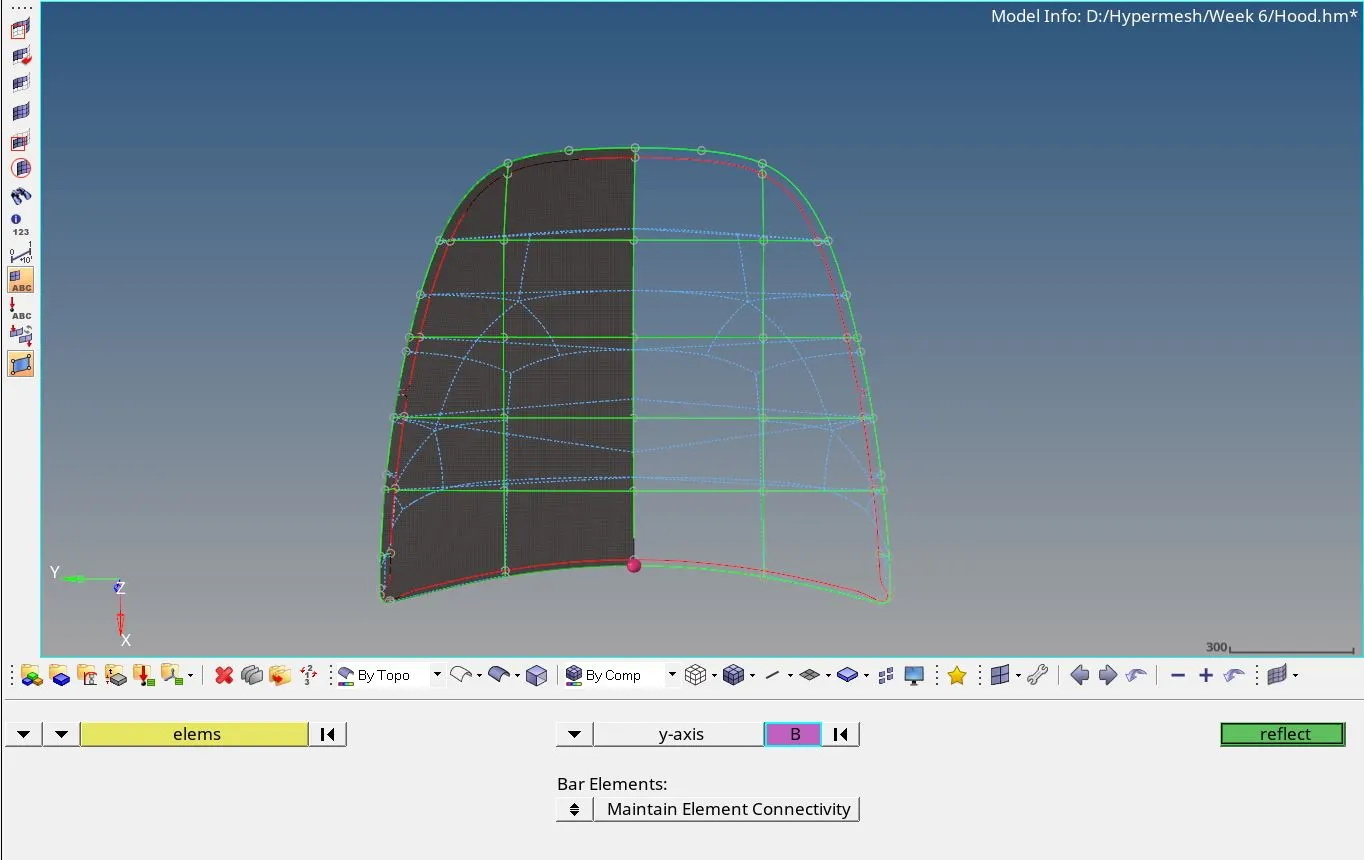
Reflect command:
-
Navigated to the tool menu page.
-
Navigated to the tool menu page.
-
Duplicated the elements.
-
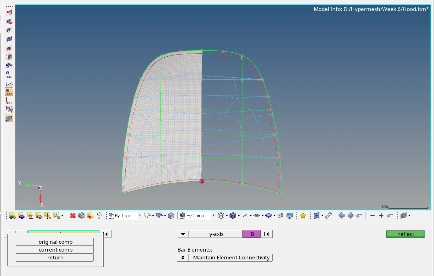
Selected axis for reflection: Y-axis
-
Selected the base node.
-
Then hit reflect button.
-
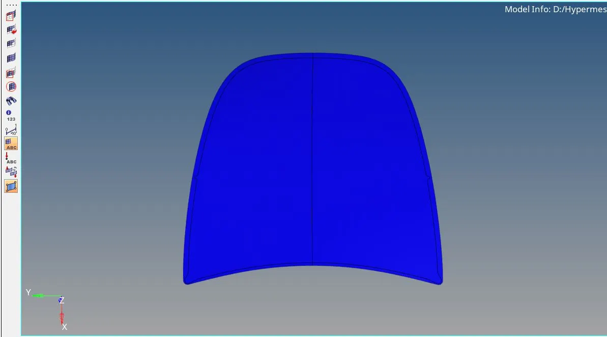
Same steps were followed to reflect the surface.
- Then quick edit panel was used to toggle free edges.
Edges and equivalence:
-
Navigated to the tools menu page
-
Selected the elements
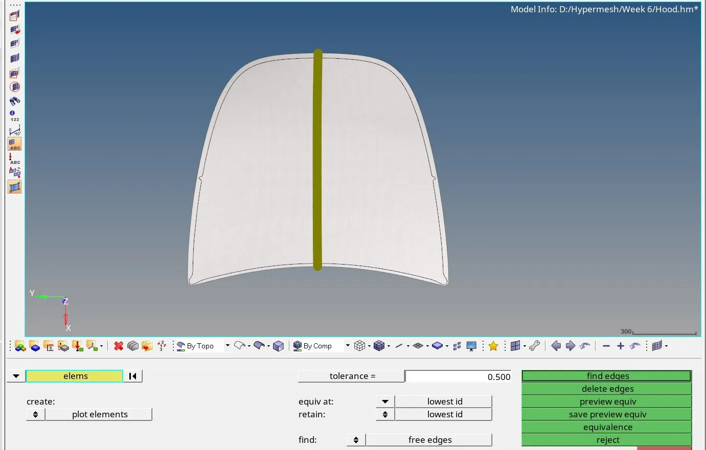
- Now hit preview equivalence tab
-
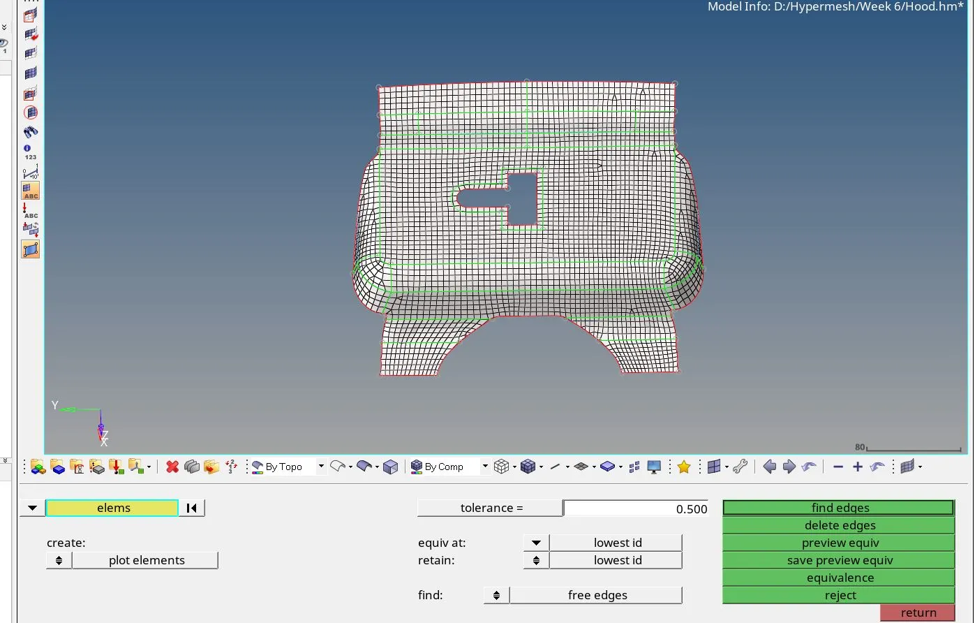
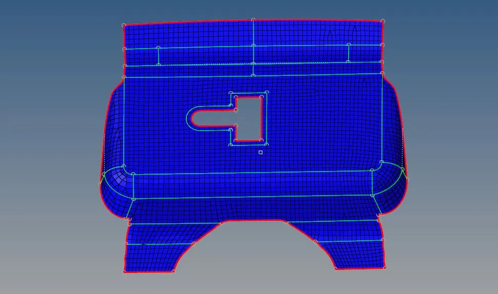
So elements not having connectivity are highlighted as shown below.
-
Then hit equivalence tab to establish the connectivity
-
Also, check free edges by clicking find edges tab. This will show any free edges present in the mesh.
Conclusion:
We have successfully performed the midsurface and 2D meshing on given component along with that also learned to find and fix elements failing in quality checks.
Note:
For reviewer, due to limitation of number nodes in student version of hypermesh, only half side of the outer extract body has been meshed.
For inner extract body the 2D meshing has been done for entire component.