Creating the appropriate connections using the given data
AIM: Create the appropriate connections using the given data in the model.
Objective:
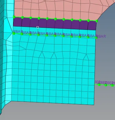
1. Right_Rail_2 & Front_truss_1:- Seam-Quad(angled+capped+L)
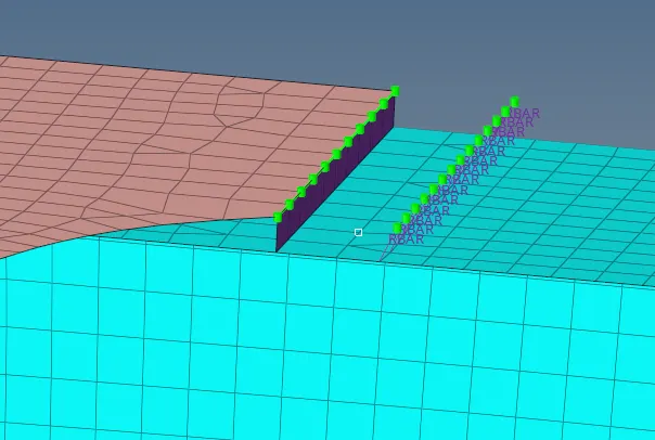
2. Left_Rail_2 & Front_truss_1:- Quad elements
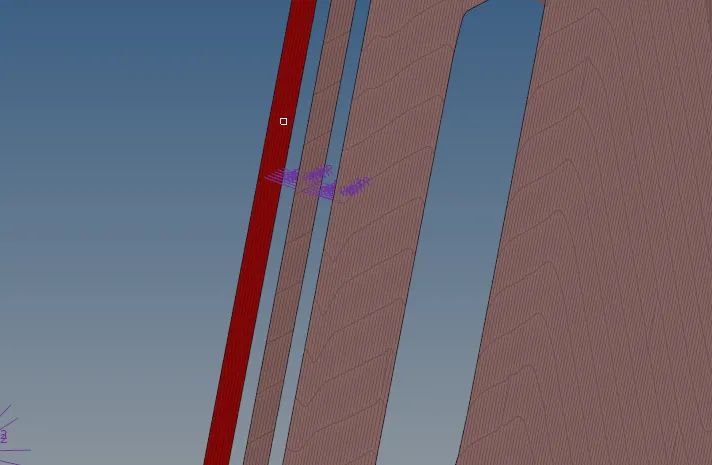
3. Front_truss_2, Front_truss_1 & Right_Rail_1:- Spot weld with 3 Layers and 5 mm Diameter
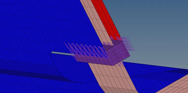
4. Front_truss_2, Front_truss_1 & Left_Rail_1:- Hexa (Adhesive)
5. Rear_truss_2 & Right_Rail_2:- Bolt Connector
6. Rear_truss_2 & Left_Rail_2:- Bolt Connector
7. Right_Rail_1 & Right_Rail_2:- Spot-weld with Rigid Elements
8. Left_Rail_1 & Left_Rail_2:- Spot-weld with Spring Elements
9. Rest all the component left Join them with suitable connectors
Theory:
Connectors are the geometric entities, which are primarily used to represent the CAD geometric connection in terms of FEA. connections can be created as a spot weld, seam weld, blots. A realized connector will be considered as the successful representation of a CAD model in the preprocessing and the connecting parts can be considered as connected.
SEAM WELD:
The process of joining the workpiece which is made of similar or dissimilar materials along a continuous seam is known as seam weld. In hypermesh, seam panels under connectors will help to represent the seam weld connection between the components.
SPOT WELD:
Spot welding is a resistance welding process that is used primarily for welding two or more metal sheets together by applying pressure and heat to the weld area. Heat for the welding process will be obtained from the resistance to electric current. Realized spot weld in hypermesh will represent the connection between components.
BOLT CONNECTIONS:
Bolted joints are one of the most common elements in construction and machine design. A connection between structural members made with plates and bolts.As opposed to a riveted or weld construction. In hypermesh, we use the RBE2 elements to represent the bolt connections since it has more stiffness.
WELD ANGLE:
Angle between the normal projection of the nodes and slant length of the weld element. It is recommended to define weld angles between o and 90 degrees
CAP ANGLE:
The angle between the normal of the first slant weld element and its adjacent side element. To define the seam weld for 0 to 45 deg CAP angle it is recommended to select <=10deg. For 45 to 90 deg CAP angle, It is recommended to select >=75deg.
RUNOFF ANGLE:
The angle between the normal of the first slant weld element and its adjective weld elements. It is recommended to define weld angles between 0 to 10 deg.
Procedure:
1. Right_Rail_2 & Front_truss_1:- Seam-Quad(angled+capped+L)
- Go to 1D/2D >select the node list>tick the retain nodes>select the components which we have to select then givethe tolerance.

2. Left_Rail_2 & Front_truss_1:- Quad elements:
- Go to 1D/2D >select the node list>tick the retain nodes>(Type =quads)select the components which we have to select then give the tolerance.

3. Front_truss_2, Front_truss_1 & Right_Rail_1:- Spot weld with 3 Layers and 5 mm Diameter:
- Go to 1D/2D >select the node list>tick the retain nodes>spot>(Type =weld)select the components which we have to select then givethe tolerance.

4. Front_truss_2, Front_truss_1 & Left_Rail_1:- Hexa (Adhesive):
- Go to 1D/2D >select the node list>tick the retain nodes>seam>(Type =HEXA Adhesive)select the components which we have to select then give the tolerance.

5. Rear_truss_2 & Right_Rail_2:- Bolt Connector:
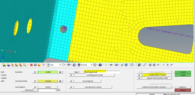
- Go to 1D/2D >select the node list>tick the retain nodes>bolt>(Bolt general)>create hole ,if none>select the components which we have to select then give the tolerance.
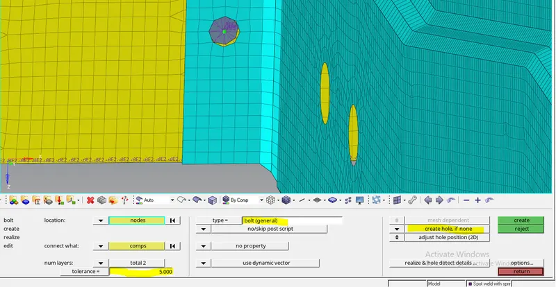
6. Rear_truss_2 & Left_Rail_2:- Bolt Connector:
- Go to 1D/2D >select the node list>tick the retain nodes>bolt>(Bolt general)>create hole ,if none>select the components which we have to select then give the tolerance.
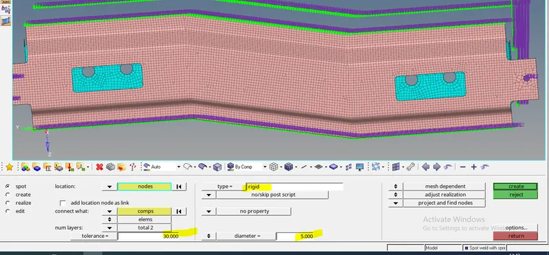
7. Right_Rail_1 & Right_Rail_2:- Spot-weld with Rigid Elements:
- Go to 1D/2D >select the node list>tick the retain nodes>spot weld>(Rigid)>select the components which we have to select then give the tolerance.
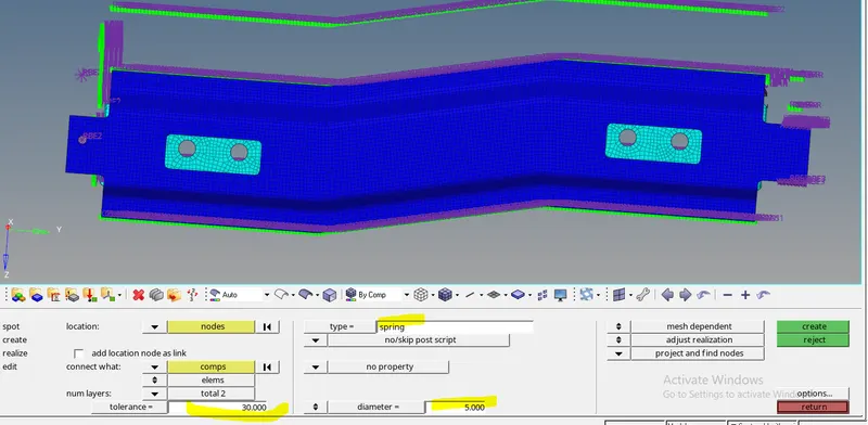
8. Left_Rail_1 & Left_Rail_2:- Spot-weld with Spring Elements:
- Go to 1D/2D >select the node list>tick the retain nodes>spot weld>(Springs)>select the components which we have to select then give the tolerance.
CONCLUSION: As per the given data, connections are created by using a different type of connectors like weld, spot, seam, springs etc.