Performing the geometry cleanup,mid surface extraction and generating the good mesh flow over given hood model with given Quality criteria.
AIM: Performing the geometry cleanup, mid surface extraction and generating the good mesh flow over the given hood model with given Quality criteria.
Given Quality criteria:
|
S.No |
Quality Criteria |
Value |
|
1 |
Target/Average length |
5 |
|
2 |
Minimum Length |
2 |
|
3 |
Maximum Length |
7 |
|
4 |
Aspect |
3 |
|
5 |
Warpage |
15 |
|
6 |
Skewness |
45 |
|
7 |
Jacobian |
0.7 |
|
8 |
Minimum Quad Angle |
45 |
|
9 |
Maximum Quad Angle |
135 |
|
10 |
Minimum Tria Angle |
30 |
|
11 |
Maximum Tria Angle |
120 |
|
10 |
Tria Percentage |
15 |
THEORY:
A car hood, also referred to as a bonnet in some other countries. it is the hinged cover that rests over the engine of a front-engine vehicle. Its purpose is to provide access to the engine for repair and maintenance. A concealed latch is typically used to hold down the hood.
Car hood basically having three main parts
1.Outer extract(which is the outer side of the hood)
2.Inner extract (which is the inner side of hood)
3.Latch(which is used for locking the hood )
4.Hinges (which are used to stand the hood when it opens)
There are various steps before going to the meshing procedure:
* Import the CAD model
*Geometry cleanup
*Mid surface extraction and assign the thickness, PID
*Meshing process
IMPORT THE CAD MODEL:
* First Import the CAD model from the files to ANSA software and go to the mesh mode there we can set the length(1mm) for perimeters as well as macros for to perform all operations properly and good visibility of model.
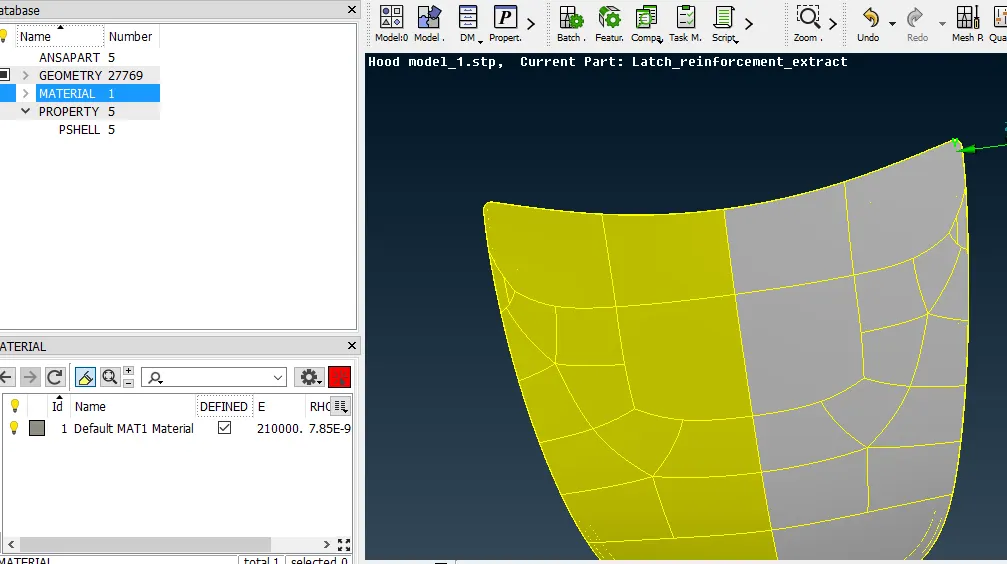
* After that do the topo to the entire model and check material Id is assigned to all property IDs and make sure that material ID should be defined as ticked in the dialogue box as shown in the below fig. If we are not defined the material, ANSA will not consider component as material.
GEOMETRY CLEANUP:
* Actually there are five parts here we should select each part and do the geometry cleanup for each part because we can identify the errors easily.
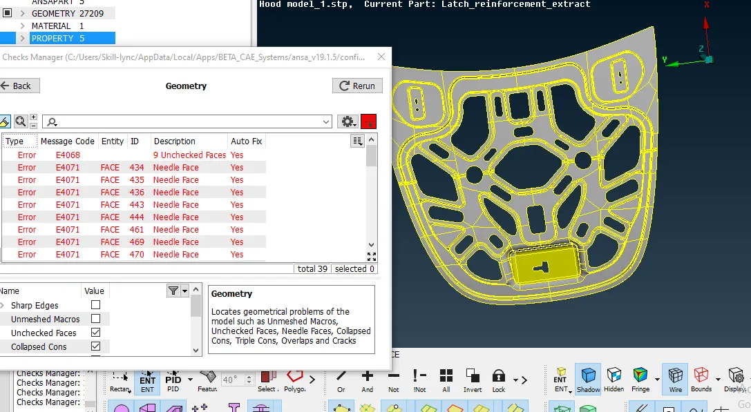
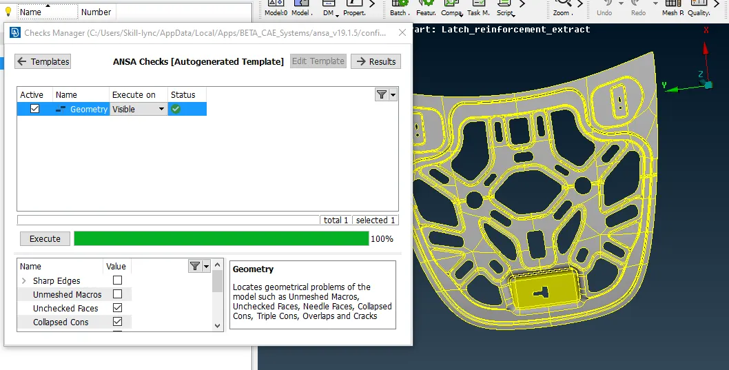
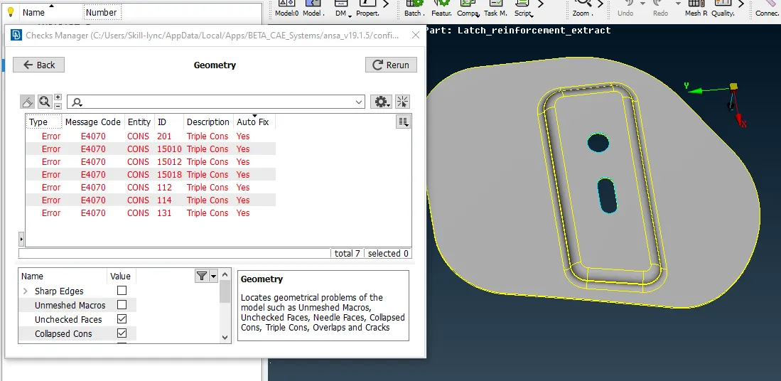
* We can check the geometry using the check geometry under the toolbar when we click on it it will show the errors like unchecked faces, needle faces, shraps edges,triplecons, single cons etc. we can remove the all those errors by using the Auto fix option. All errors cannot fix by the auto-fix option there are some errors like triple cons we can go area by area and remove them manually. After removing those we can again execute the check geometry until it shows execute 100%.
*In below images we can see that errors before geometry clean up and after geometry clean up.
 |
 |
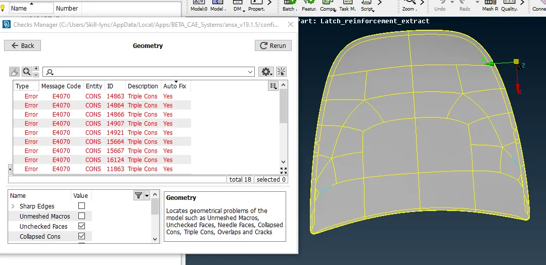
*Here we can see lots of triple cons present in the outer extract model, those can be resolved by using the Auto fix option below the fig.
 |
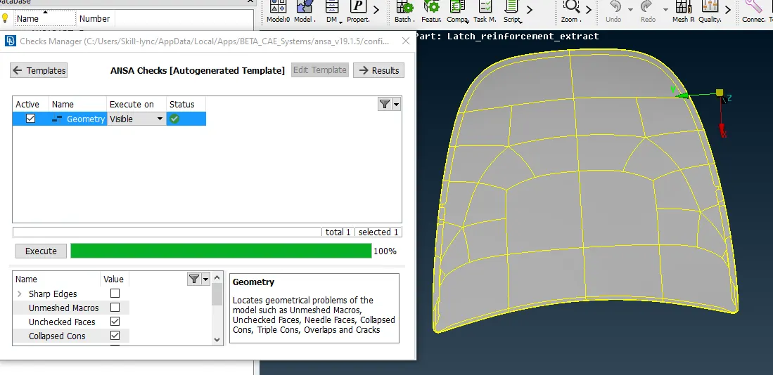 |
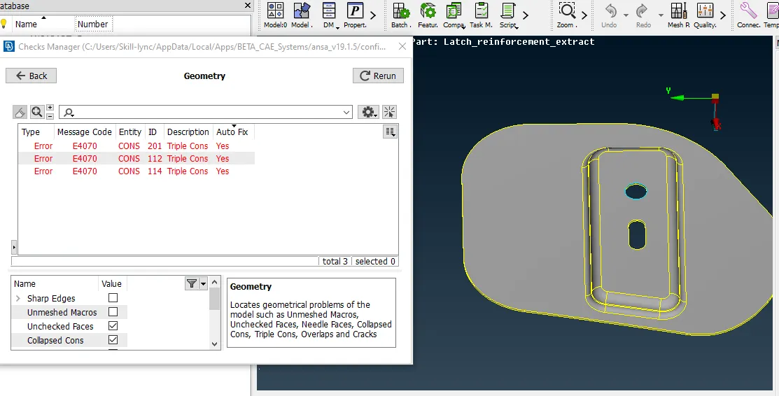
* Here we can observe that after the using the Auto fix also we can observe the three more errors in the right side fig. In this situation, we can go with the area by area to resolve this issue.
*we can use release cons option after release the cons we can go with topo at that area then it will make the double con.
 |
 |
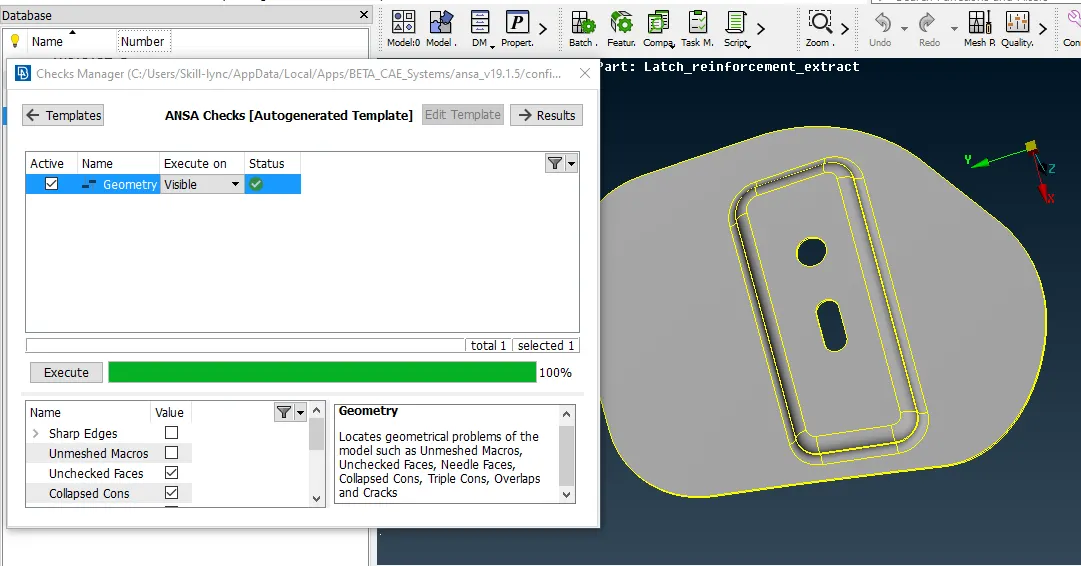
*We can see that the triple con is transferred as Double con as shown in below fig and there are no more errors in this component.
MIDSURFACE EXTRACTION:
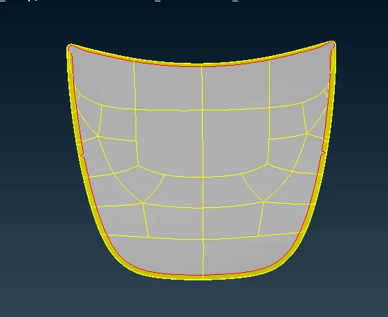
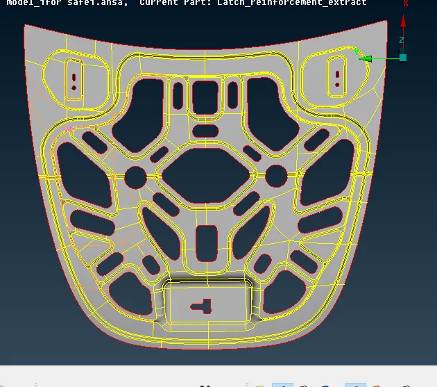
*We should extract the midsurface for the whole component, first go through the individual component and measure the thickness to extract the midsurface.
*Go to offset option under faces and make sure click on the feature angle to select the entire component then give the offset value then midsurface occurs in the middle of your parent body.
*We can create the new property IDs for each component by using the set PID option it will ask shell card click on that and define the thickness.
*Here we created a five different PIDs from past five PIDs which we have by default.
The mid surface of outer extract:
The mid surface of inner extract:
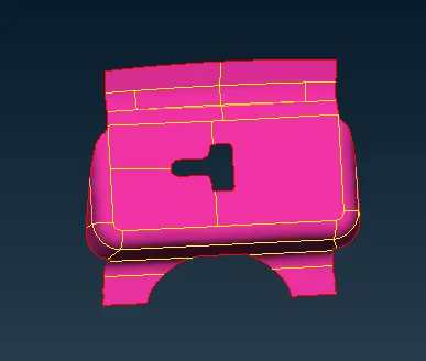
Midsurface of Latch :
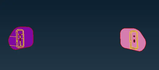
Midsurface of Hinges:
* We should check the geometry again after the extraction of the mid surface, this time you make sure that disable the single cons in the dialouge box because after the extraction of the mid surface there no more shared surfaces in the boundaries and there commonly represented as single cons.
MESHING PROCESS:
A mesh is a network that is formed of cells and points it can have almost any shape of any size and is used to solve partial differential equations. each cell of the mesh represents an individual solution of the equation when combined with foe whole network results in a solution for the entire mesh.
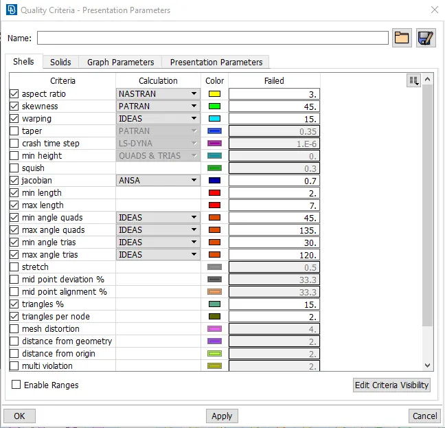
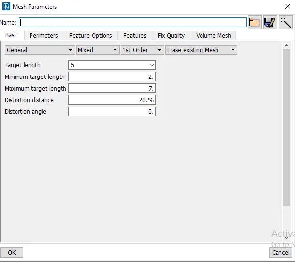
*First we should put on the mesh mode then we should assign the Quality criteria, presentation parameters, mesh parameters as shown in the below image.
*In presentation parameters enable the tick to the % of elements and put the details of demand effect to all details.
*In mesh parameters we should give the target element length, min length and max length as shown below images.
Quality criteria :
Mesh parameters:
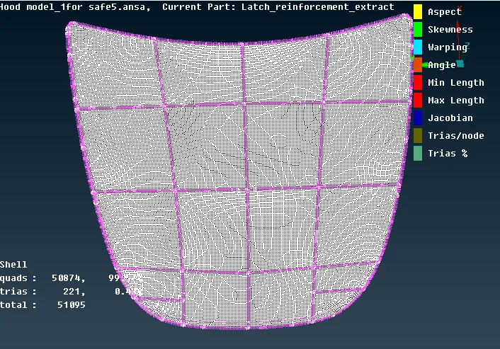
* In 2D meshing for midsurface we are going with mixed mesh flow with both quads and trais as per the given Quality criteria.
Meshing on inner extract:
* First we can identify the model, In our model of an outer extract there is a symmetrical part we can identify it with the help of the Rmdbl then we came to know that both sides are symmetrical.
* Here what we can do is delete the half portion of the component, after meshing is done on the part we can easily reflect the other side it will reduce our work.
*After deleting the half portion, we can delete the unwanted construction lines and hot points in the model and keep checking the fillet regions and small regions remove those unwanted lines in order to get the better mesh flow.
*We can create a new construction line perpendicularly in some area which we can define the area to get the better mesh to flow over there. In the fillet area, we can compromise on the trais because in that area we avoid those trais over there.
*Perpendicular construction lines always recommended over edges and fillets to come with the better mesh flow.
*Then we can go with the best mesh option in mesh generation box, the mesh is done by area by area to get good mesh if any quality issues are coming we can go with the reconstruction option and after reconstruction uses the smooth option to smooth the mesh.
*We can remove the trais using the split option, paste option and swap option to element the trias and make sure that there no tria elements in the edges of the component we can swap the trais using the swap option.
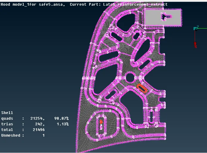
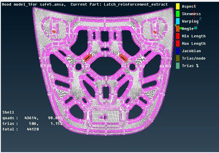
*After the clearing all quality issues we can reflect the other side of the component using the transform option -symmetry-3 points plane as shown below images.
Meshing on the outer extract:
Meshing on the half part: After refected:
 |
 |
Meshing on outer extract:
*Here also same as the inner extract we can delete the half portion and reflect it back after meshing.
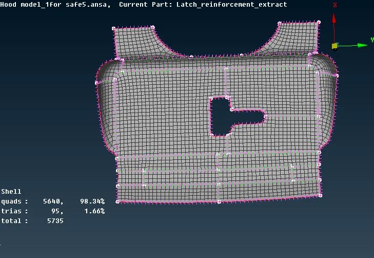
Meshing on Latch:
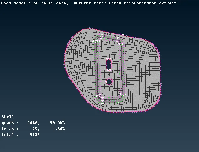
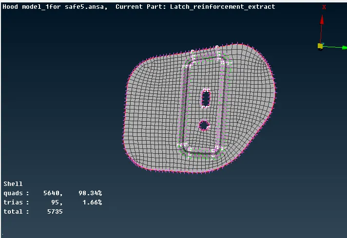
Meshing on two Hinges:
 |
 |
Learning outcomes:
* I this challenge I am able to understand how to obtain better mesh flow over some critical areas on fillets and also eliminating the trais by using the split, swap, past options.
*I was able to understand the doing the midsurface of a component using both auto midsurfacing and manual midsurfacing with options midsurface and offset.
*I have got an idea about the hood model and how to perform a better mesh flow over the sheet metal components.
CONCLUSION:
The given hood model is checked for the geometrical errors and taken the mid surfaces of component, it has meshed with the max quad percentage is 99.19% and trais percentage is 0.81% with given quality criteria.
Link for the model:
https://drive.google.com/file/d/1PcFzfjaRca4abykRVZDspkzY_y-T4i6X/view?usp=sharing