Week 9-Challenge
Task:- Understanding Connectors in Hypermesh and their application at various locations in the frame assembly.
Tools used:- 1D/2D connectors, automesh, connectors browser
The model given is a frame assembly whose midsurface has already been extracted. We need to review the sub-components for any faults in the topology and improve it. Then-after, the component's sub-parts need to be meshed by assuming some mesh quality parameter. The frame-assembly CAD is shown below;
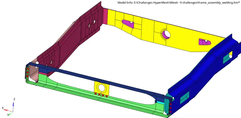
The different sub-components are separately visible in the components collector tab. The connectors required for the components are listed below;
1. Right_Rail_2 & Front_truss_1:- Seam-Quad(angled+capped+L)
2. Left_Rail_2 & Front_truss_1:- Quad elements
3. Front_truss_2, Front_truss_1 & Right_Rail_1:- Spot weld with 3 Layers and 5 mm Diameter
4. Front_truss_2, Front_truss_1 & Left_Rail_1:- Hexa (Adhesive)
5. Rear_truss_2 & Right_Rail_2:- Bolt Connector
6. Rear_truss_2 & Left_Rail_2:- Bolt Connector
7. Right_Rail_1 & Right_Rail_2:- Spot-weld with Rigid Elements
8. Left_Rail_1 & Left_Rail_2:- Spot-weld with Spring Elements
9. Rest all the component left Join them with suitable connectors.
Process:-
1. Right_Rail_2 & Front_truss_1:- Seam-Quad(angled+capped+L)
The seam connector is available in 2D option in Panel area.
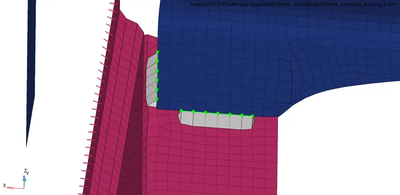
This type of Angled+capped+L seam weld connector requires us to select the nodes by path, and define spacing according the the element avg. length. We must retain nodes to ensure that node position is retained after realizing the connector. The involved two components will be selected and a search tolerance will be provided within which the hypermesh will look-out for the nodes and elements of the other selected components. Then we need to assign values of weld angle, cap angle and run-off angle for the weld elements. I have chosen a value of 60 degrees, 75 degrees, and 10 degrees in my model.
Here, since we understand that the mesh lay-out in these two components may be unidentical. Therefore, we must change the settings from quad transition to remesh.

THe FE representation of seam type (Angled+capped+L) is shown below;
2. Left_Rail_2 & Front_truss_1:- Quad elements
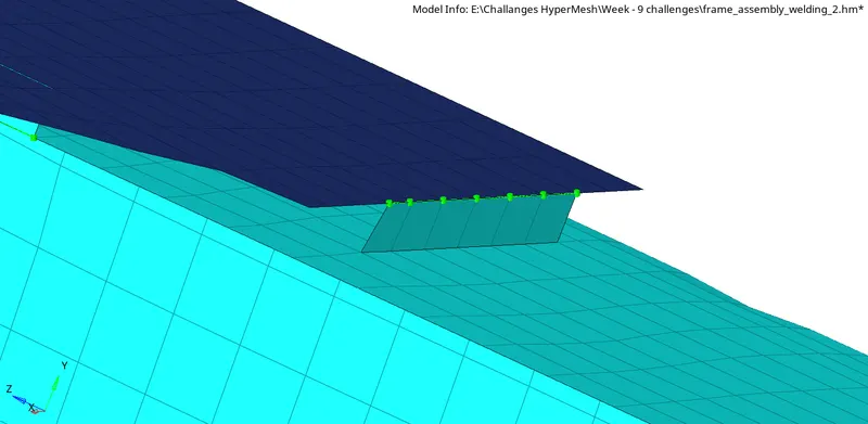
This is a seam type connector only, with the only difference that all the elements representing the seam will be quads without any run-off or cap or weld angle.
The procedure is same as the one above, and we will change the setting from quad transition to remesh to make the connectors realized.

3. Front_truss_2, Front_truss_1 & Right_Rail_1:- Spot weld with 3 Layers and 5 mm Diameter
The spot weld allows the different layers of metal sheets to be joined at a weld spot. The process is similar, selection of nodes by list, selection of components, specifying the spacing and tolerance values according the the element size and distance between the plates to be joined, selecting the type of spot connector as "weld". We can chose "adjust realization" and "find nearest nodes" to make the connectors realized. Since here we are trying to connect three layers together, we must select num layers: total 3.

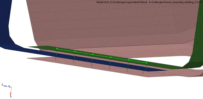
4. Front_truss_2, Front_truss_1 & Left_Rail_1:- Hexa (Adhesive)
Hexa (Adhesive) is a seam connector type which has similar process of application. However, there are a few extra options which can change how our adhesive is represented. We have options to give more number of strips and coats along the width and thickness of our adhesive element.


5. Rear_truss_2 & Right_Rail_2:- Bolt Connector
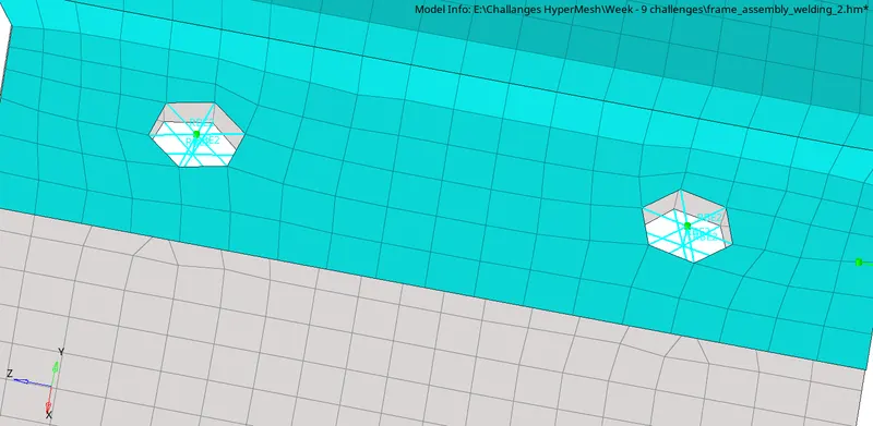
Bolt connector is available in 2D option in panel area. THe process is simply selection of nodes, selection of components, num layers, specifying tolerance according to distance between plates and selecting the type as bolt (general). We must keep the option selected as "create hole, if none" & "adjust realization".

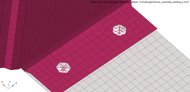
6. Rear_truss_2 & Left_Rail_2:- Bolt Connector
7. Right_Rail_1 & Right_Rail_2:- Spot-weld with Rigid Elements
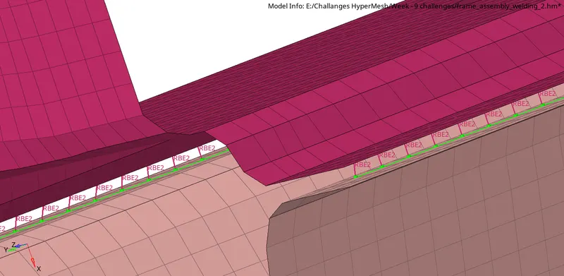
Spot weld with rigid elements is available in 2D option in panel area. The selection of spot weld location is by node path. And the process is the same, setting ghe spacing value, tolerance search value, num layers. We can choose to keep two options under adjust realization - "project & find nodes" , or "find nearest node". With the first option of "project & find nodes", we may find that a few RBE2 elements are not getting linked at the nodes of the other component. There, we may manually replace the nodes of the RBE2 link to nodes of the corresponding element in the bottom component.

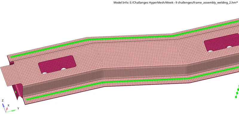
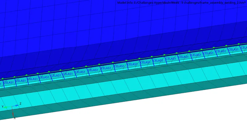
8. Left_Rail_1 & Left_Rail_2:- Spot-weld with Spring Elements
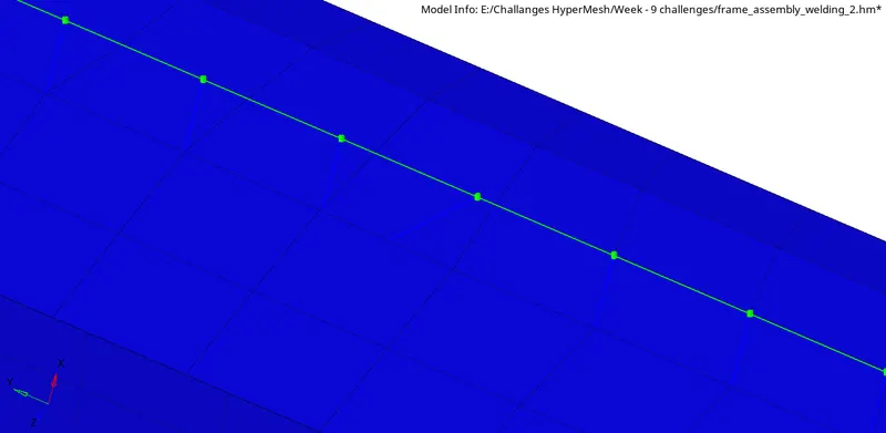
Instead of rigid RBE2 element, there is a spring element type CELAS1. The procedure is similar as above with just a change in type of element. We can keep "agjust realization" with "find nearest node".