Week 8-Challenge
Task:- Creating tetramesh of the given geometries and ensuring suitable element quality parameters.
Tools used:- 3D tetramesh, translate, check elements, 2D Automesh, fix 3D elements, edges
Theory:- Tetrameshing, as the name suggests, is the mesh generation that shall only have tetrahedron basic elements.
The linear tetrahedral element is made up of four nodes and it has 1st order element formulation, whereas a second order tetrahedral element is made up of 10 nodes. A second order element more robustly controls the mapping of complex areas of the geometry.
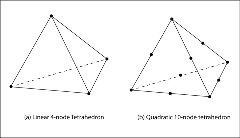
{Picture borrowed from a Researchgate article}
Procedure:- There are several methods to obtain tetramesh of a component.
- Method 1 :- Using 2D tria mesh to generate 3D tetra mesh. Usually, a 2D mesh is generated where we ensure the element quality in length specified. And then using it as an enclosed region we map the 3D tetra mesh which is mapped from and enclosed within the 2D tria mesh. The algorithm mostly used by HyperMesh is Delaunay's algorithm.
- Method 2 :- Using "Volume Tetra" option to directly generate 3D tetra mesh out of a solid or a surface geometry. But this option is only applicable to geometries which are closed in entity.
- Method 3 :- Utilizing the Quick Tets utility tool of HyperMesh, a similar tool as "Volume Tetra" to obtain 2D trias as well as 3D tetra mesh. This option overrides the requirement of having a closed geometry or closed surface while at the same time allowing all the features of "Volume Tetra".
The initial steps are the same for all three sub-tasks, i.e. to import the geometry file, organise different entities in separate component collector, clean-up the geometry for surface or continuity errors, toggle the construction lines, etc.
A.) Housing Model (Elements sizes: Min- 2mm, Target- 5mm, Max- 7mm, Tet collapse: 0.15)
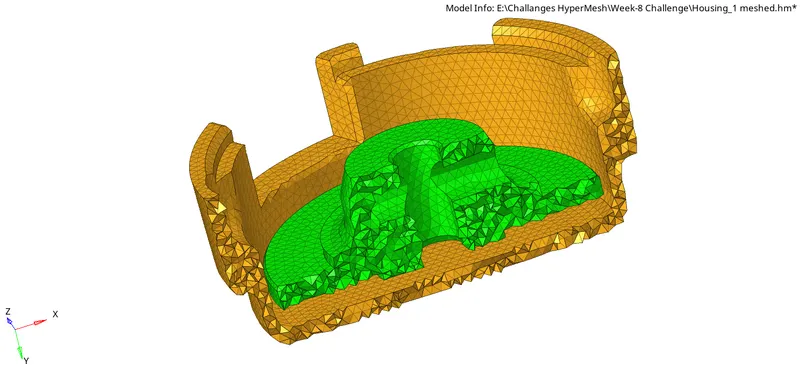
The model consists of two components which can be refered as inner & outer. They both need to be organised into separate component collectors. This is a simple component, hence after any necessary topology improvement is done, we can make use of Method - 1. Here, we will create automatic 2D trias on all component surfaces and improve their element quality in length if any. After that, we can easily map the available 2D elements to 3D tetras using Tetra mesh -> Float trias/Quads to tetra mesh -> Entity type as elems & remeshable -> mesh. Be sure to do complete selection of all the 2D trias that were formed in automesh. Mapping using floating trias allows the software to change the 2D trias generated if in-case there is any problem in the tetras generation within the enclosed volume. The picture below shows the mesh resulted;
B.) Crank Housing (Elements sizes: Min- 2mm, Target- 6mm, Max- 7mm, Tet collapse: 0.15)
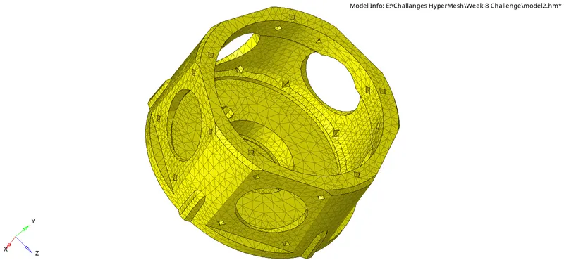
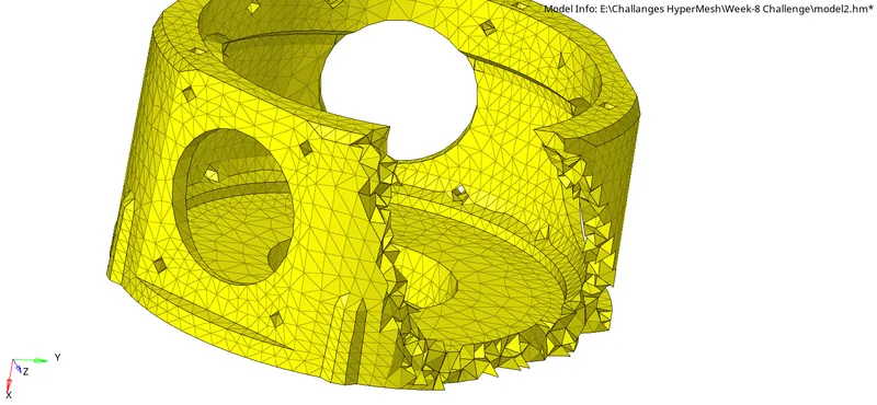
This is a typical model where there are many intricature surfaces and curvatures. Hence, we can prefer to use Method - 2. In this method, we go to Volume Tetras -> Select the enclosed volume by surface (just by clicking on our model) -> [(Optional) check mark the "use curvature" & "use proximity" options with minimum element size being 2mm }-> mesh. Use curvature and proximity option will tap the cornering features and fillets and chamfers with smaller sized elements thus mapping them properly. However, if the element size falls below the decided value, we may choose to not use this feature. The picture below shows the mesh resulted;
C.) Axle-Assembly (Elements sizes: Min- 2mm, Target- 6mm, Max- 7mm, Tet collapse: 0.15)
Axle-assembly has four different components identifyable from the component collector tray itself. The best practice in this task can be to create four another component collectors just for tetra mesh elements, and leave the original four components for 2D tria meshing. This ensures that a trial and error of different methods is smoothly possible and allows deletion of 3D tetra without bothering 2D trias, or vice-a-versa. All the four components were tried with different methods, the resulting mesh generated is as shown below;
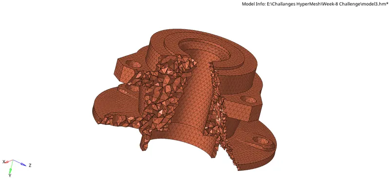
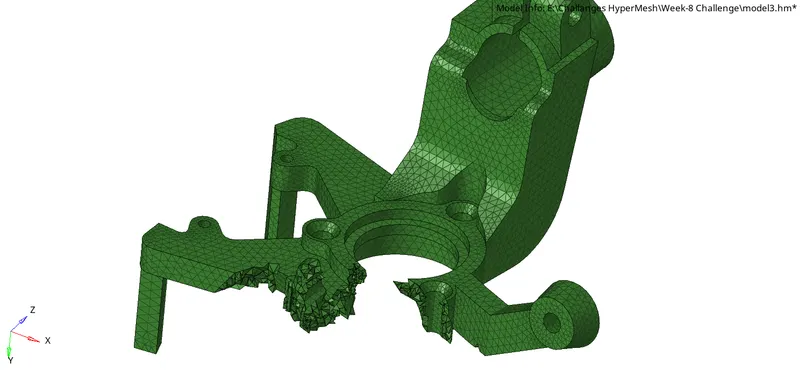
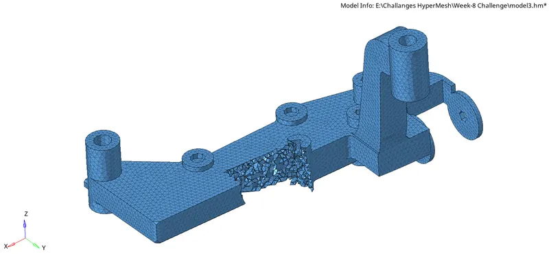
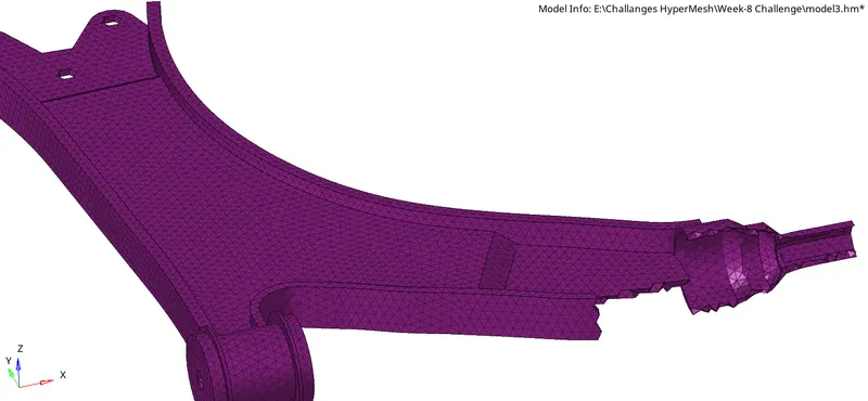
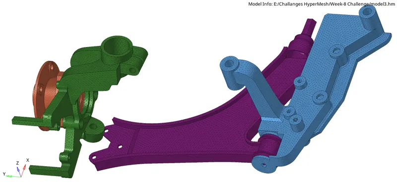
Quality Check in 3D Tetrahedral elements:- Unlike in 2D quad or tria meshing where we place more emphasis on size of the element, A/R & other parameters, in 3D Tetrahedral meshing, we place more importance on Tet Collapse - usually a near-planar 3D tetra elements are formed in an auto-mesh generation process. Either this planar element has not enough height dimension or is located at the very edge of the component in which case it is advisable to remesh that and other nearby elements.
Tet Collapse is mathematically computed as minimum of `h /(1.24 ⋅ √ (A))`
Tet Collapse usually should not fall below a limit (our case is 0.15). Any element with value below the required set value is a collapsed tetra, and needs to be improved.
The 3D tetramesh panel provides a direct option to improve the Tet Collapse failing elements in one shot. Fix 3D elements (Solid Mesh Optimization) is the option under Tetra Mesh which computes the failing elements under any particular quality parameter. And it provides an easy option to fix all of them within the algorithm.
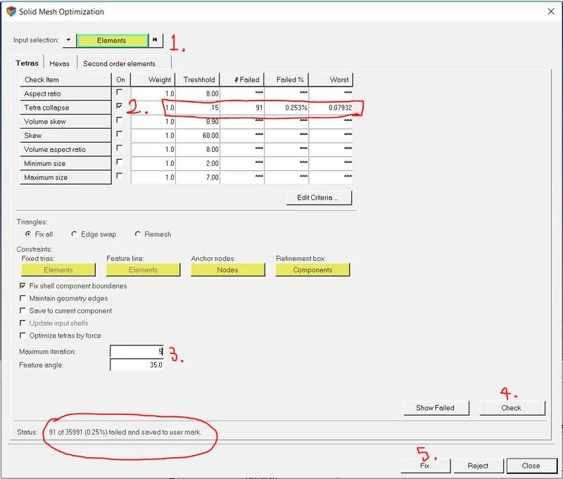
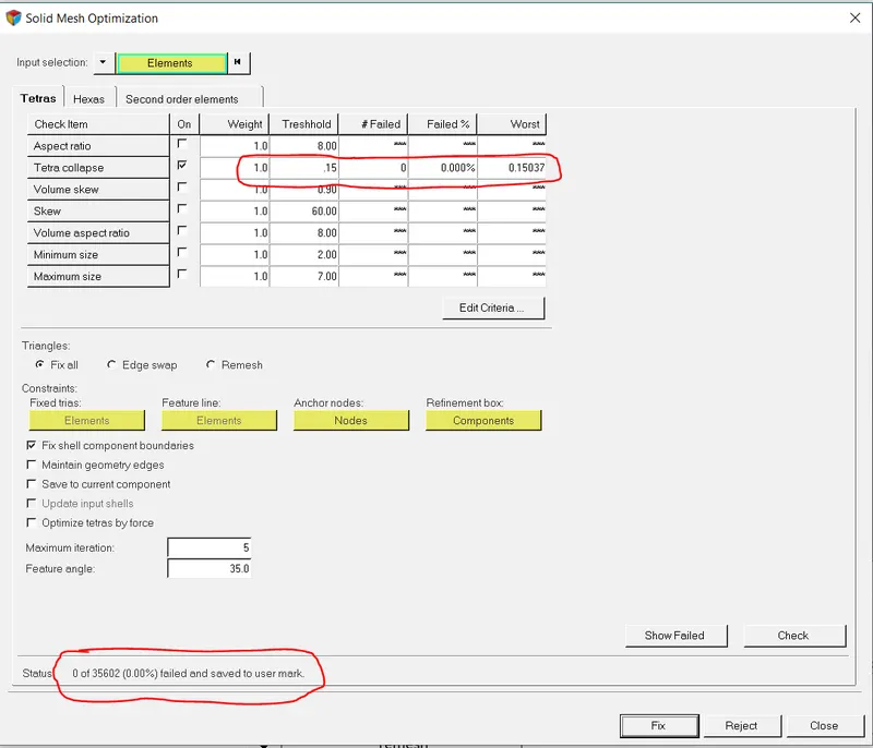
Almost all the times, this method improves the failing elements and our model is good to go. However, under certain conditions a few elements still cannot get automatically improved using this method. In that case, we need to check the failing element quality and save them in the user mark collector to be retrieved later. The retrieved elements are masked and each individual element that appears on the screen need to be treated for Tet Collapse parameter. 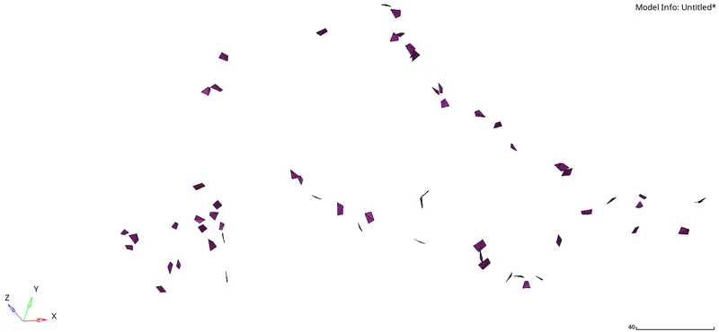
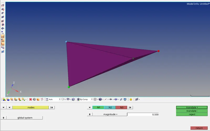
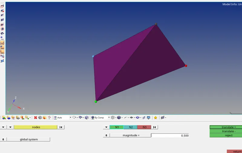
We need to translate a node out of four nodes whose height appear to be too small from the opposite surface area. Under Tools -> Translate -> select node that needs to be affected, select the three nodes that form on the area opposing that node, give any test value of magnitude by which the node shall be moved -> translate +,- . Check again for the failing 3D elements in Tet Collapse in the "check elements" tab. This process is repeated over every Tet collapse failing element.
Conclusion:- This exercise was a good way to understand the different methods to obtain 3D tetramesh. The choice of going with 2D -> 3D Tetra meshing seems more promising as we can be certain of element quality in the 2D mesh from the start itself, and then derive the 3D tets with its enclosed volume. The choice of Volume tetra is also a convenient one but it requires a closed geometry which is normally achievable by some topology refinements in the initial steps. Also we have the flexibility of working on any solid element in the Hypermesh software directly which is much convenient but often compromises the element and mesh quality.