Week 6- Challenge
Tools & Operations used :-
Autocleanup, automesh, midsurface, surface, node edit, quick edit, edge edit, dimensioning, edit element (split), quality index, elem cleanup, rebuild mesh, check element (duplicates, connectivity, save failed), mask, edges, normal, dependency, penetration, project, reflect.
Abstract :-
The bonnet of an automobile is a simple enclosure containing several sub-components. The bonnet is the closure mechanism which houses the power-train, engine components, AC components in several conventional car types excluding the modern EVs. Also, it is aerodynamically shaped to reduce drag resistance at medium to high speeds. A hood must also pass certain safety tests laid down in the automotive standards to ensure minimum damage in the event of a frontal crash such as pedestrian head impact. Hood structures these days have been drastically modified in terms of weight by use of composite light weight structures. The meshing of this hood closure is done with the purpose of simulating a dynamic crash event such a Head Impact Collison (HIC). This report shall only discuss the 2D meshing exercise with view of a dynamic analysis to be done later. A 2D mesh is generally preferred for those components whose cross-sections remains within 5 mm and is uniformly thick throughout its geometry.
Introduction :-
The exercise of meshing is a key stage in any analysis; static structural or dynamic. Usually the idea is to break the available CAD model of a system in several Finite element which comprises of the full model when attached at their nodes. There are associated challenges to maintain a desired quality of the meshed element, known as the Quality criteria. This report is one such exercise where different methods of 2D mesh generation will be explored and a meshed assembly of a car’s bonnet will be prepared. Here we are having four individual components which will be meshed according to set values. These four components are Inner panel, Outer Casing, Latch & hinge.
We generally prefer a quad mesh or a quad-tria mix mesh style. The choice of only quads in static structural simulation is acceptable since a quad element is not as stiff as a tria element. Excessive stiffness in a tria element is not suitable for constant load application simulation where it would over-predict or under-predict the result if a greater number of elements are not used. Quads bend in the third axis when a load is applied at one of its nodes making it the best choice for simulation such as bending of structures, deflection under continuous load. Although the trias are not flexible, they are excellent in transmitting and channelling the energy in a proper direction and ensures proper mesh flow in complex geometries having features like flanges, sharp edges, holes. Hence, they are used in transient and dynamic simulations like crash, high speed impacts, drop tests where the energy flow is of interest to an engineer.
Meshing with trias and quads have its own set of rules. When having quads in structural static simulations, the presence of rotating quads in the geometry in ignorable. However, rotating quads are not desired in dynamic simulations as they disrupt energy mesh flow. Likewise, when having trias in the FE model, one must make sure that they are not located at the edge of a circular feature, fillet, and not forming back-to-back or opposing in concentration.
Methodology :-
Firstly, we require a CAD model in .stp file-format. It shall be imported in the OptiStruct environment as a geometry. Our CAD model has 4 components as mentioned before. Each component shall be treated individually.
- Choosing to work on the Latch first, we turn off the component and element view of every other sub-components except that of the latch. The visible geometry shall be visualized in terms of Topology.
- Next step is to extract the mid-surface by offsetting the planes and sweeping throughout the model. The extracted mid-surface can be viewed in a separate component. Now, we need to clean-up the geometry by either using the autocleanup or by manually defeaturing and toggling-off the feature-lines or construction-lines wherever needed. And, we must must give washer split trims at circular surfaces and holes.
- Using the automesh feature, the component is meshed. Before doing this operation, we must edit the parameters and element criteria from Preferences menu in the menu bar. We need to set the edge fillet recognition to values such as 9 or 10 to ensure that rounded edges are eliminated before any meshing operation.
- Having the meshed model autogenerated does not ensure proper capture of surfaces and features. Sometimes certain missing surfaces introduces element errors such as dysconnectivity, sharpness in the surfaces leading to warpage and skewness of the elements capturing it. Hence it is advisable to run the automesh once, observe and note the regions of improvement, reject the auto-generated mesh and then go back to improving the mid-surface that we got earlier. Delete any conflicting terrains, align the feature lines which looks and falls properly on the surface, and then re-fill the surface.
- Again, after this process of back-and-forth refinements, we can now automesh the part. This step is now critically handled since the mesh generated can be given several local improvements by modifying the number of nodes such that proper flow is visible. After pressing ‘return’ we no longer have the option to return to the earlier stage. We must now run automesh in small packets or areas, or we can rebuild mesh wherever the mesh is visibly not appropriate.
- During the rebuilding and automeshing operations, we take special care to eliminate the rotating quads, merge opposing trias, remove trias from holes, egdes, fillets, or those excessive in concentration. This is continued till we have better nodal connectivity, and know that all the elements are passing the quality required.
- For any component that is fairly symmetric, we can choose to mesh only one-half of it and reflect it to the other half later. The process remains the same for every component whose 2D meshing need to be done.
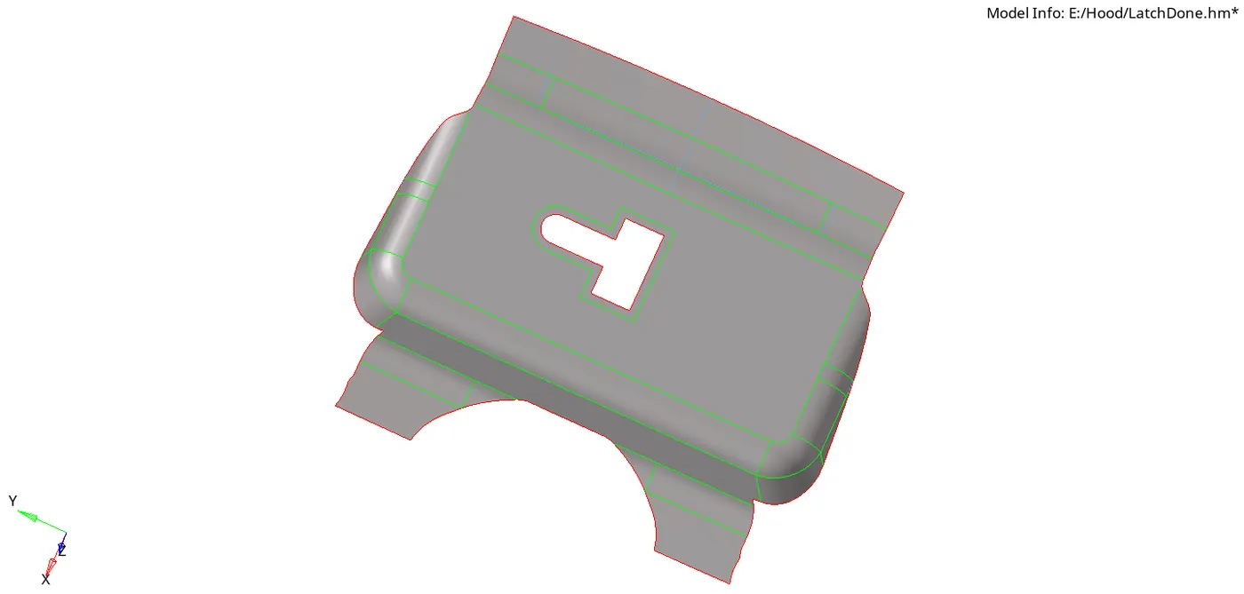
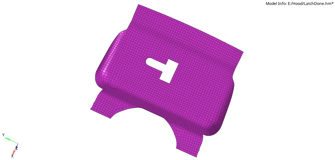
A.) Latch Model Before & After meshing
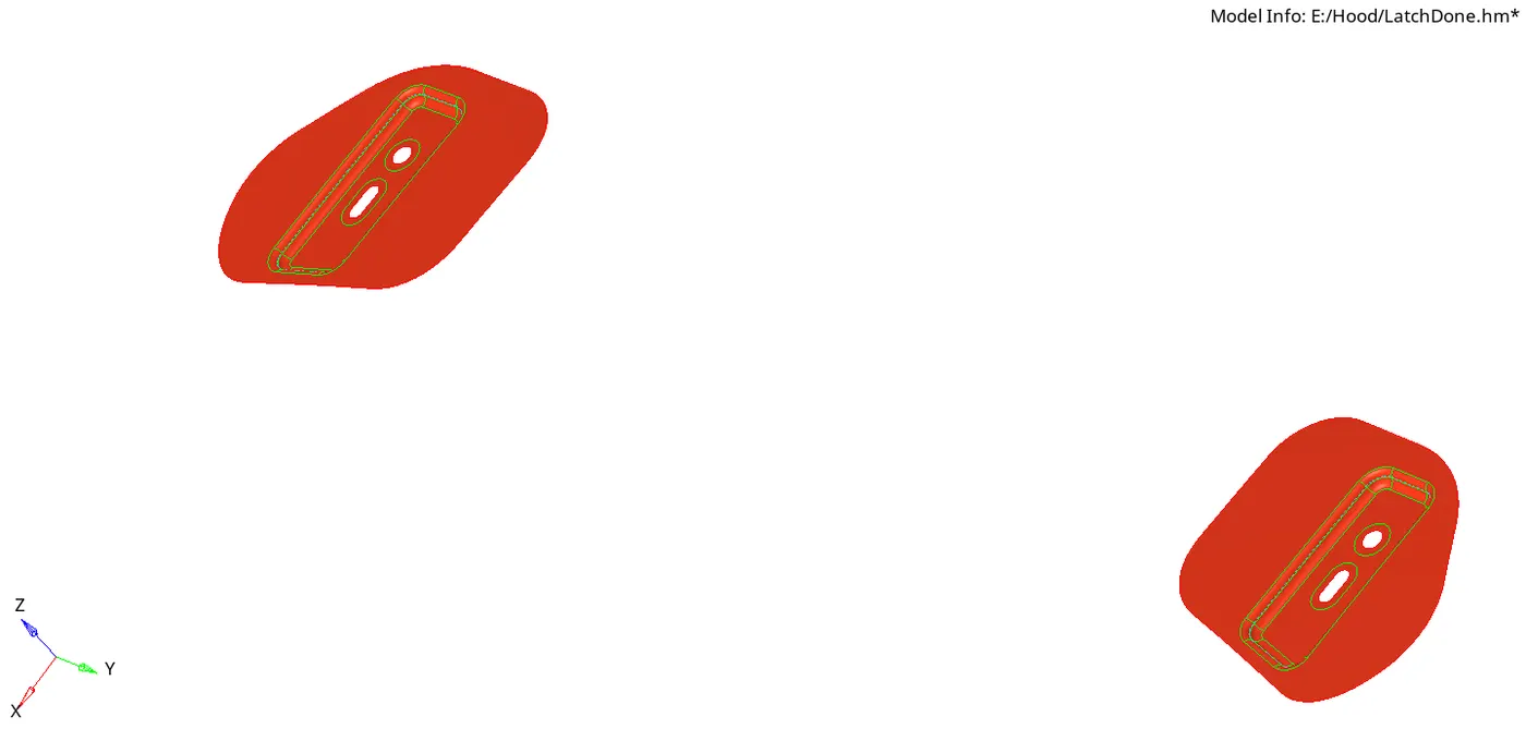
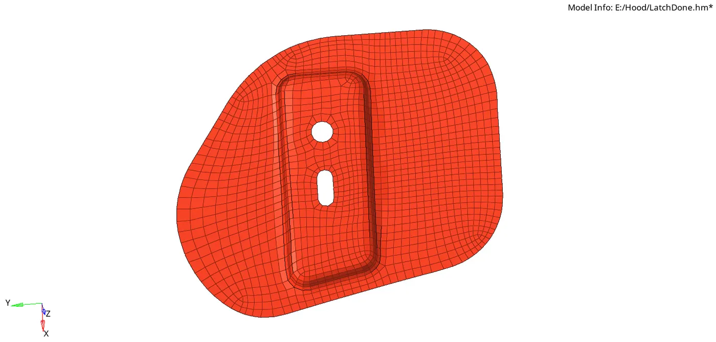
B.) Hinge Model Before & After meshing.
C.) Outer Panel Model Before & After meshing.
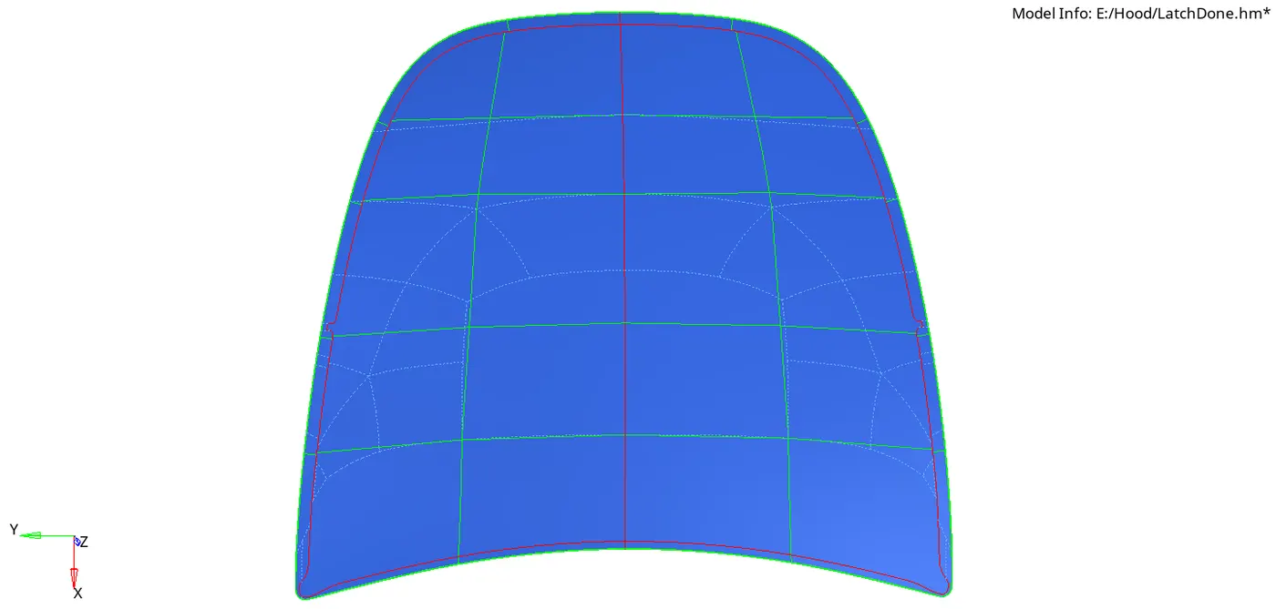
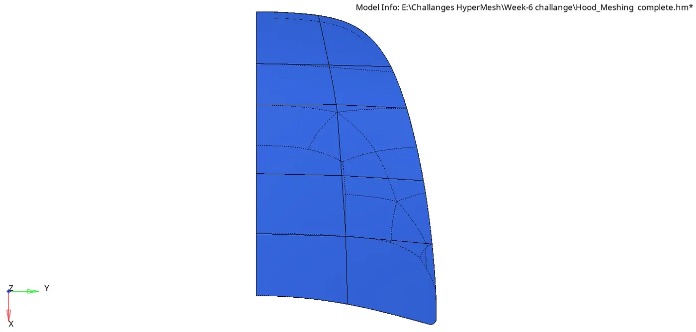
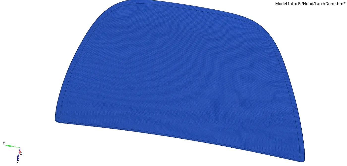
D.) Inner Panel Model Before & After meshing.
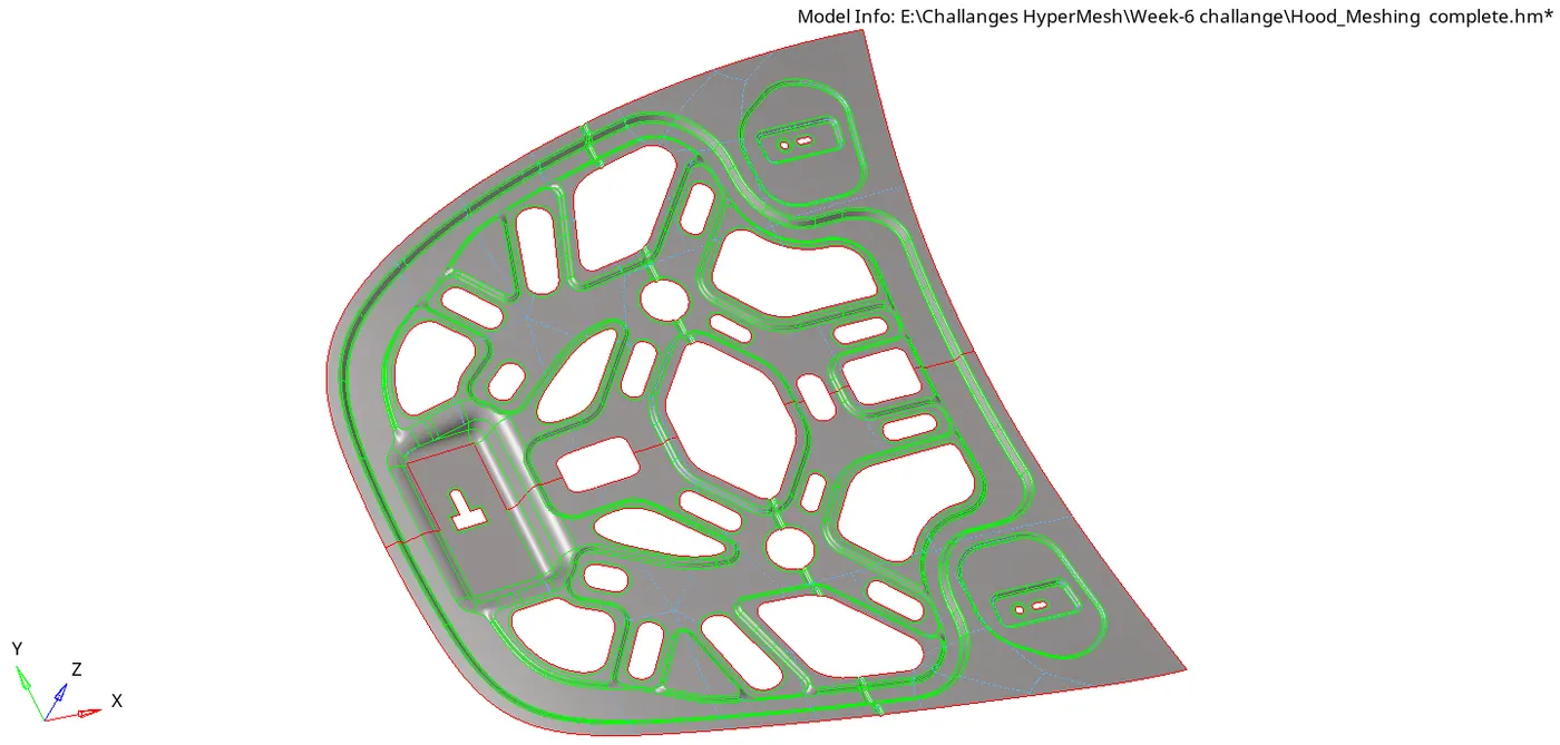
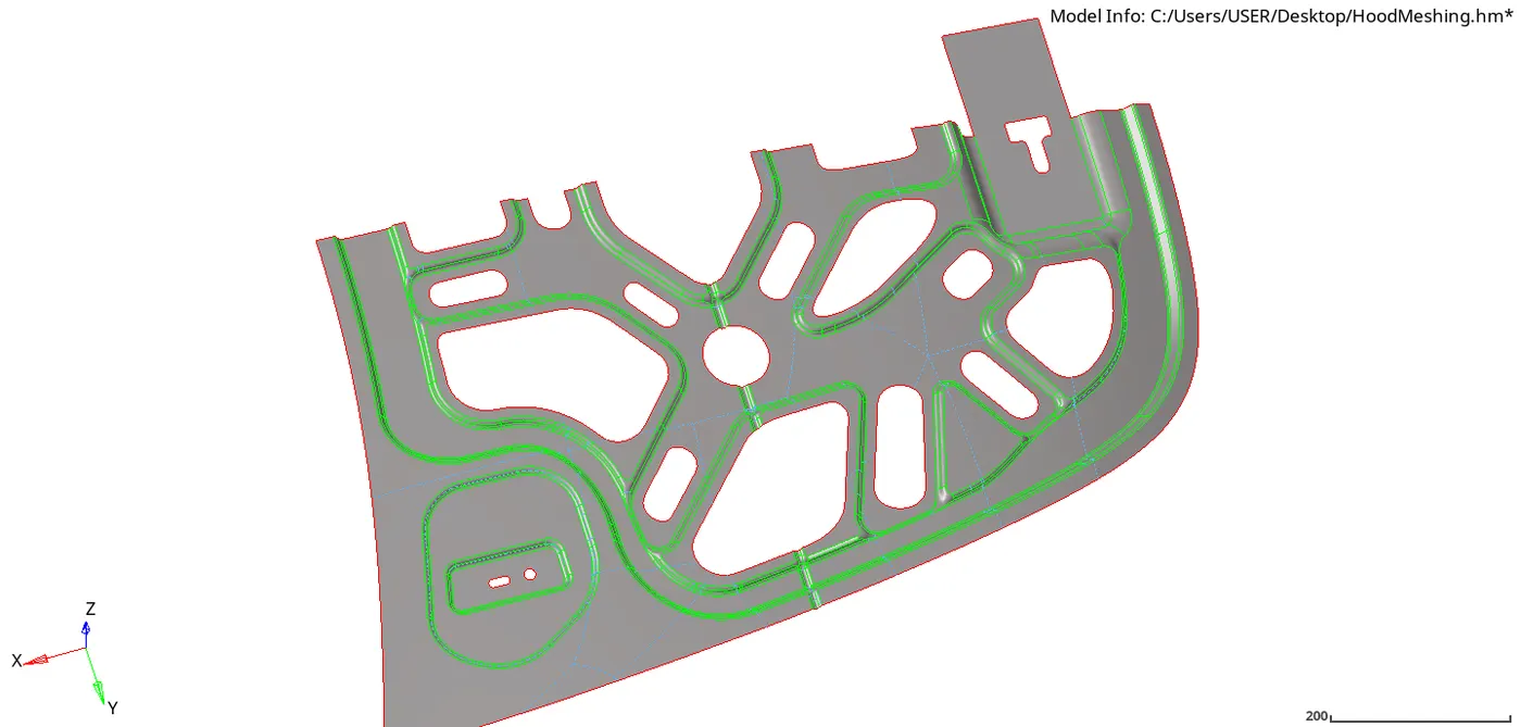
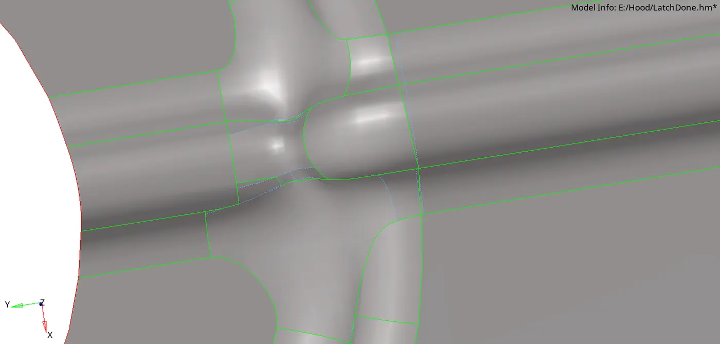
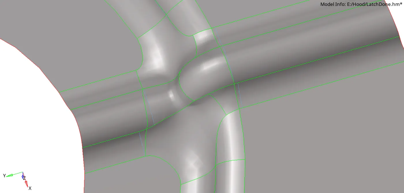
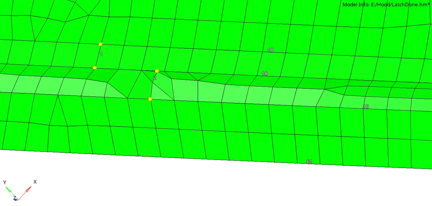
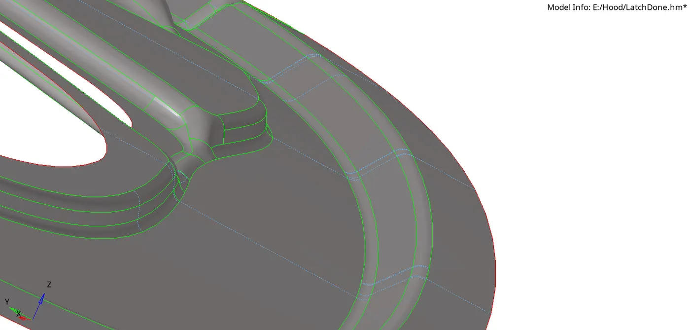
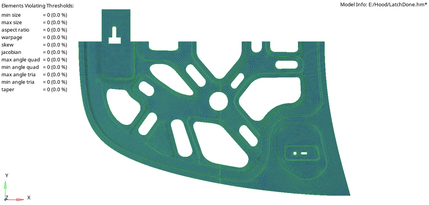
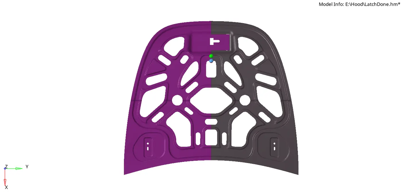
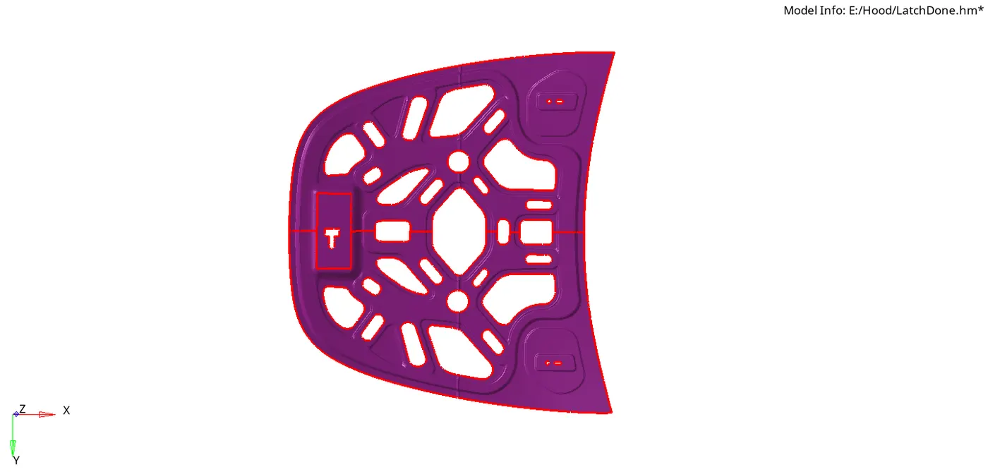
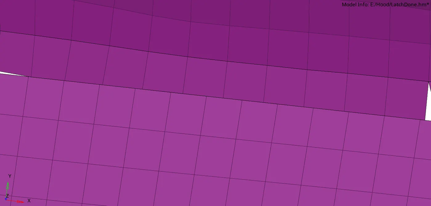
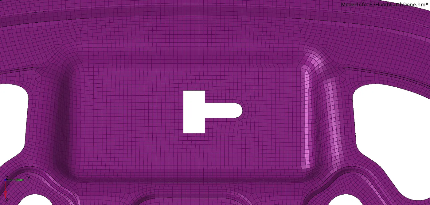
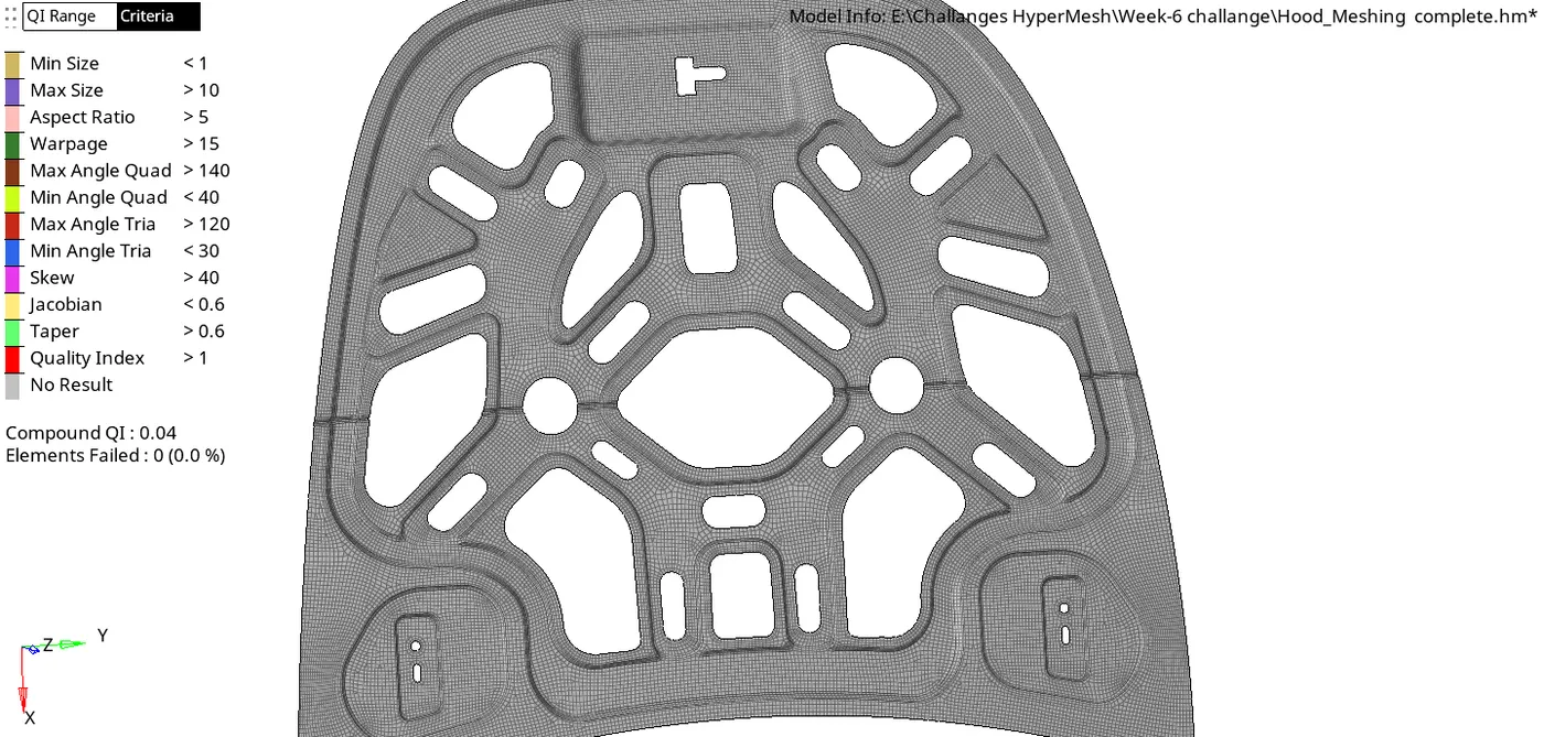
In the inner panel images above, you will find a few cases where we need to mend the surface continuity by deleting the questionable surfaces or feature lines and then re-filling them. Also, when working with such a model which has continuous fillets, we need to manually provide trim construction lines so that the meshed model captures it in the continuity. The pictures also shows how the one-half of the panel has been meshed and its elements have been reflected at the end. After reflection, we find that the nodes are not connected at the edge line of reflection as they should be. We also encounter the problem or unequal nodes at both sides of the partition line. These nodal connectivity issue can be improved by first ensuring equal number of number of nodes at both sides and then finding free edges present among them to obtain meshed elements equivalenced at either lowest or highest id to the elements at two sides.
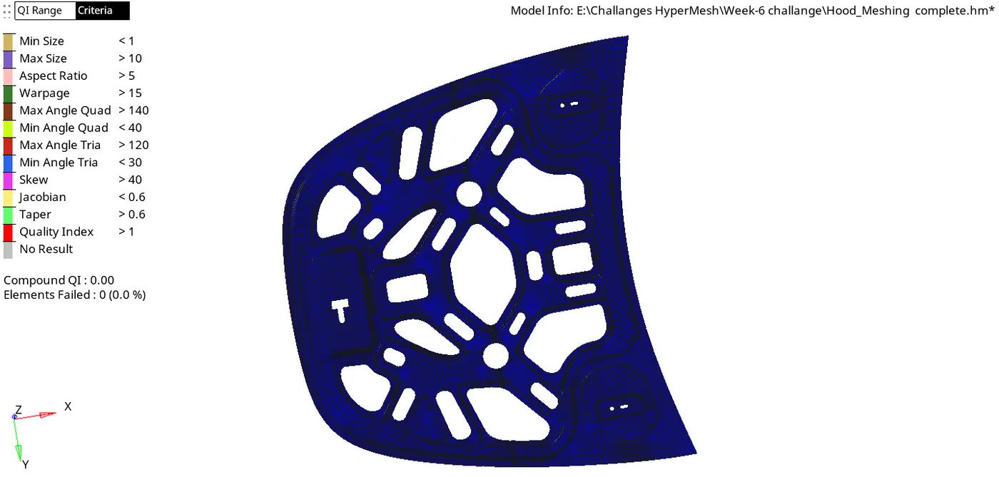
Keeping the Element colour mode by "Element Quality" will keep us informed of the failing elements and we won't be required to keep on checking element criteria from the 'check element' tool.
FE Model check :-
When all the components have been meshed successfully, we must lastly ensure that there remains no duplicates, penetration and dependencies among the Finite Elements, otherwise the model needs to be reworked.
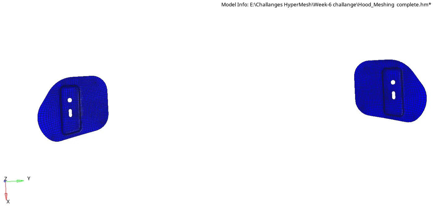
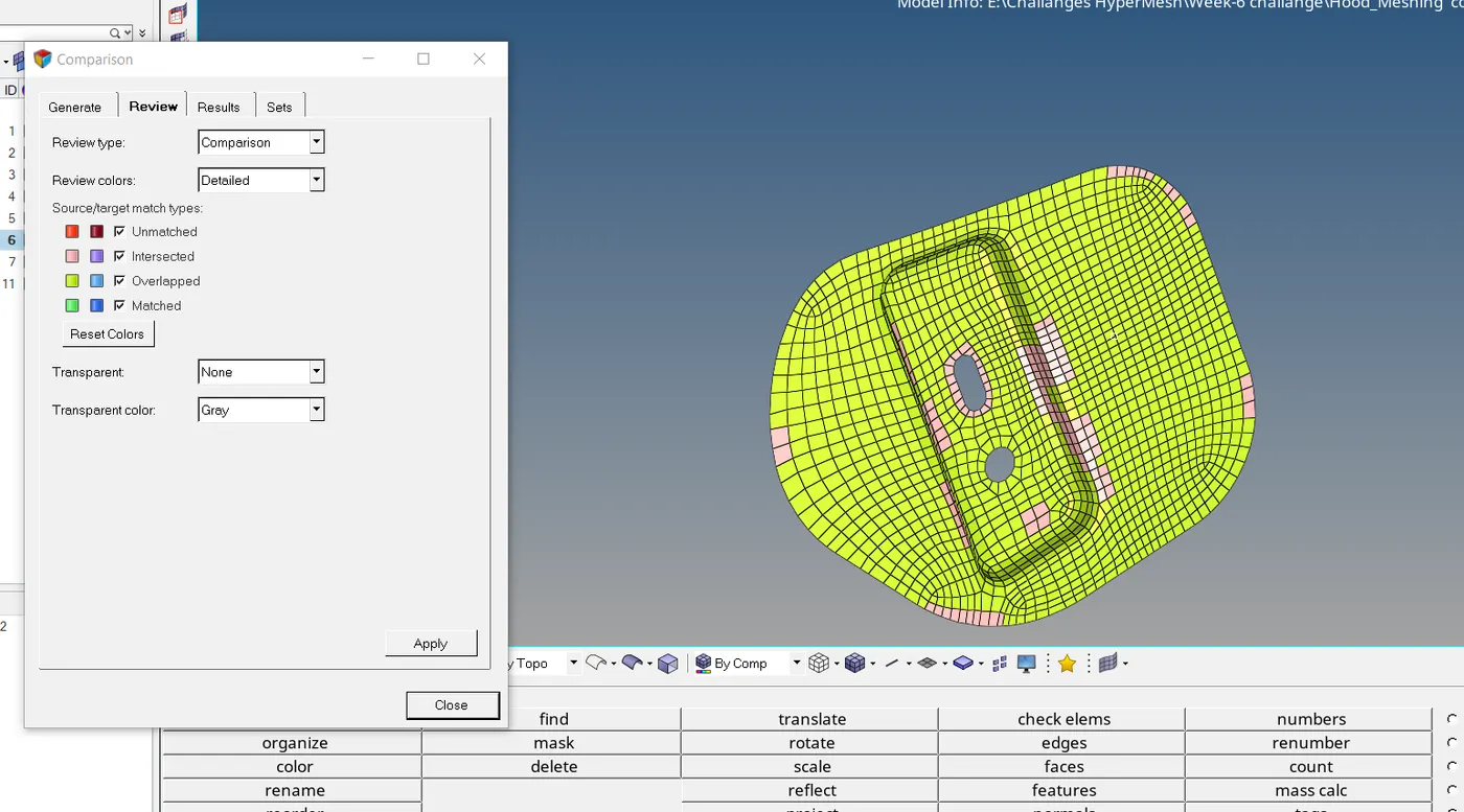
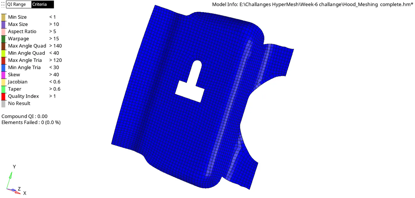
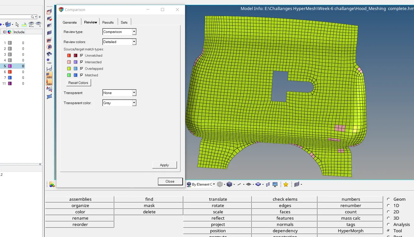
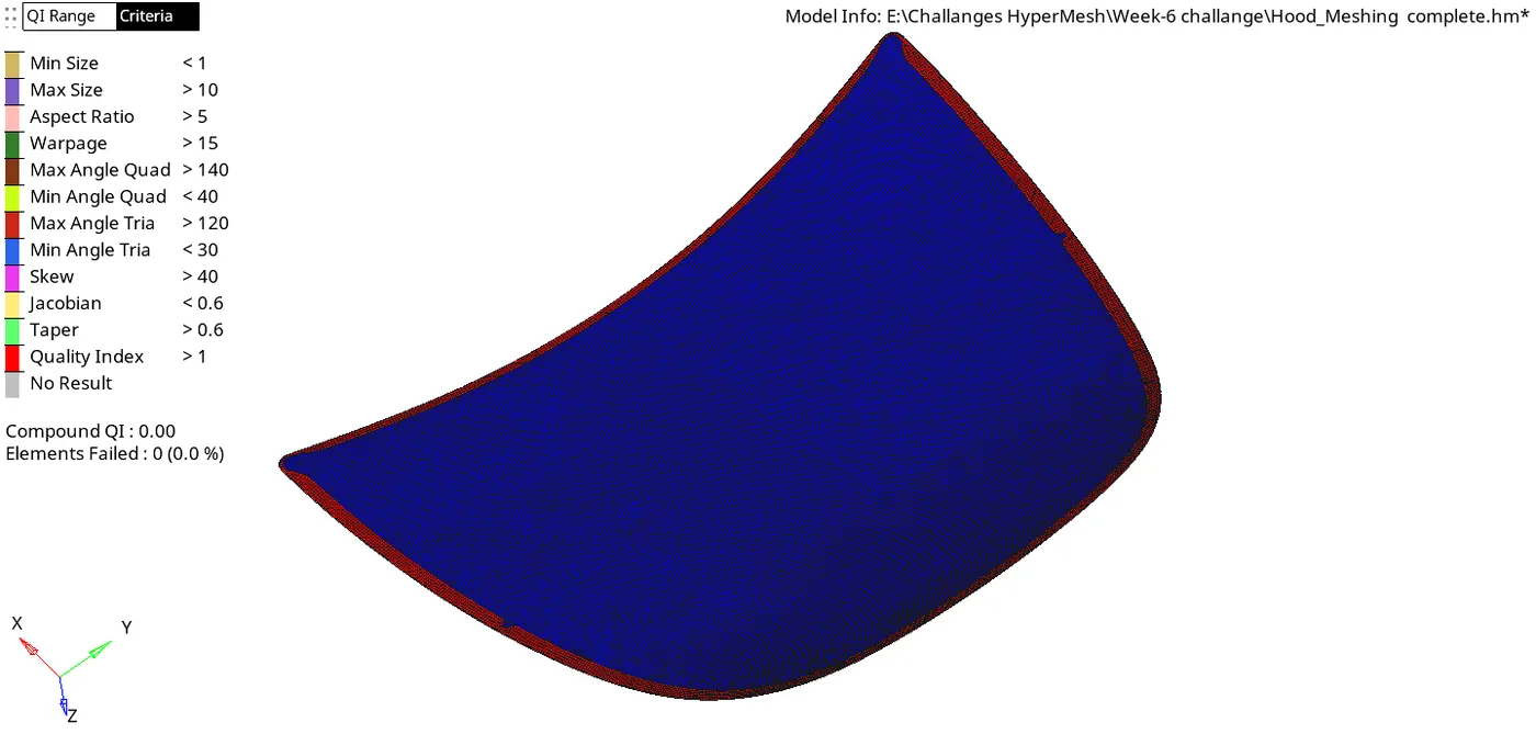
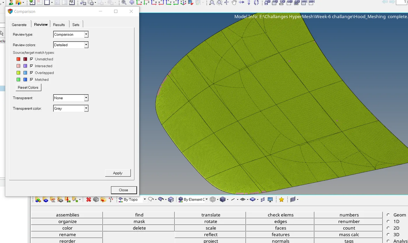
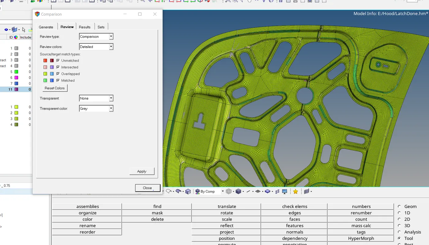
A few checks such as element 'normal' & 'Comparison' are done to sufficiently say that our model is fit for further use. 'Normals' indicates the direction in which each finite element is supposed to react when met with a load or force. All elements must be colored in either blue or red, depending too the direction of reaction desired. 'Comparison' is, as the name suggests, the ideas of how appropriately & accurately does the meshed model captures the base model. Below are a few pictures that throw a light on these model checks.
Learning Outcome :-
This project teaches the complexities that one can observe while in a meshing task of such a complex geometry. More than just generating auto-mesh, this exercise makes us observe and learn how the element types can be manipulated and how nodal connectivity works across such a component filled with several features and geometric intricacies. We learn at the end how to prepare our CAD geometry such that the meshing stage is smooth.