Week 9-Challenge
OBJECTIVE:
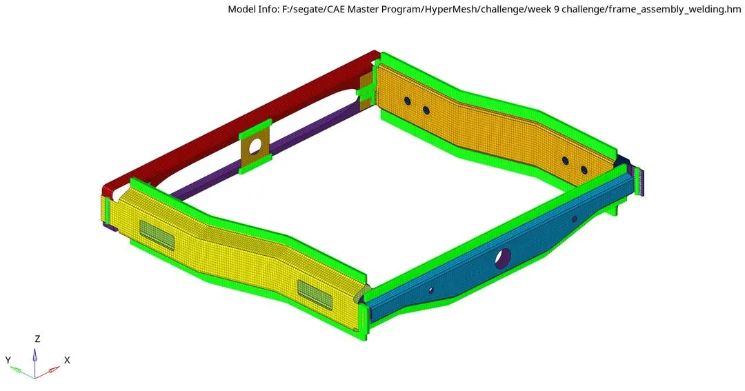
The objective of this challenge is to 2D mesh the give parts and connect them with suitable connector.
CAD MODEL IMAGE:
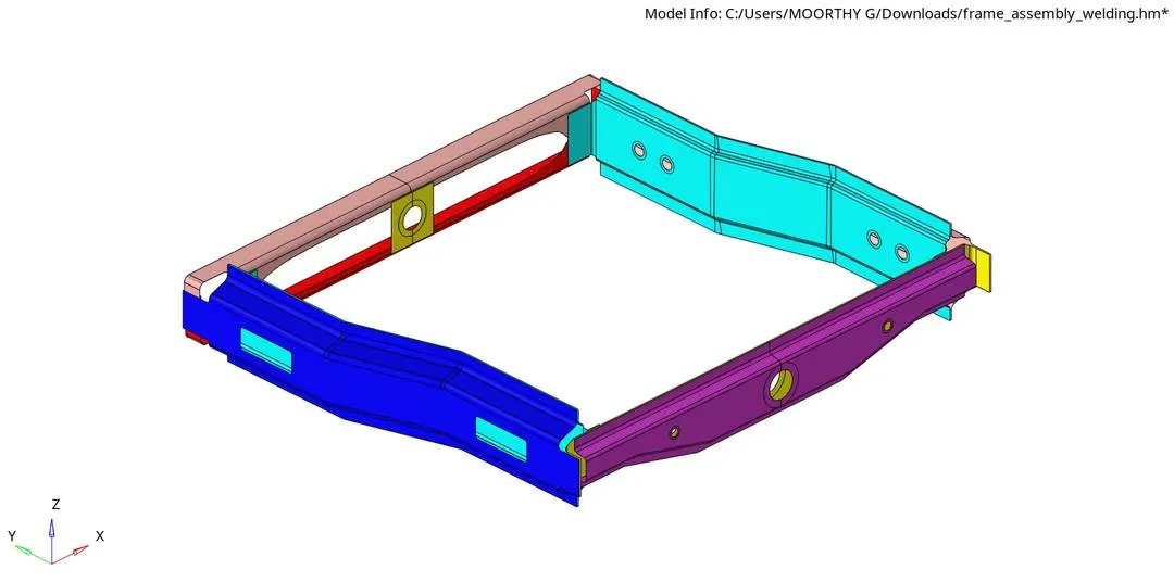
PROCEDURE:
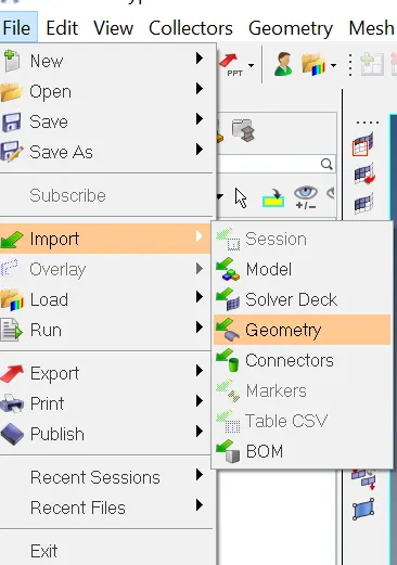
Step-1: Importing the Geomentry
File->Import->Geomentry.
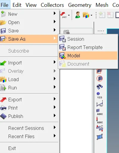
Step-2: Save the File.
File->SaveAs->Model.
Step-3: set up file criteria.
Preferences->File criteria Settings.
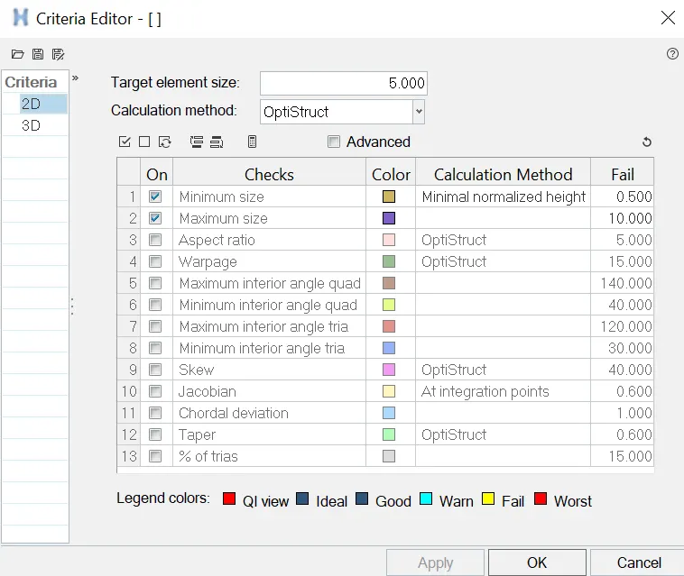
set the target element size to 5mm, minimum as 0.5mm, maximum as 10mm.
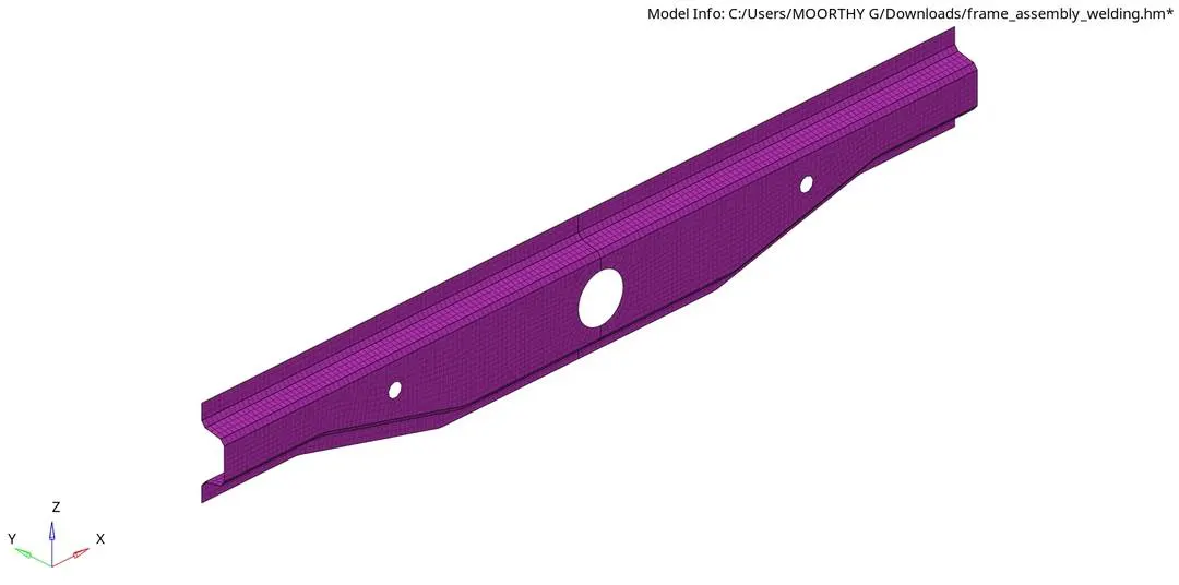
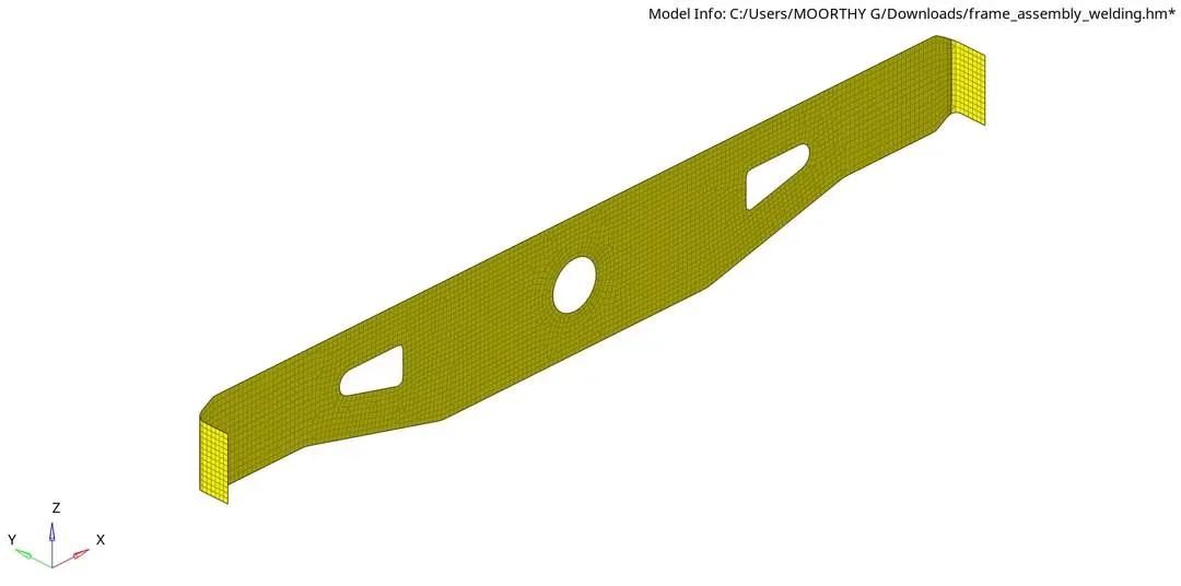
Step-4: Creating 2D Mesh.
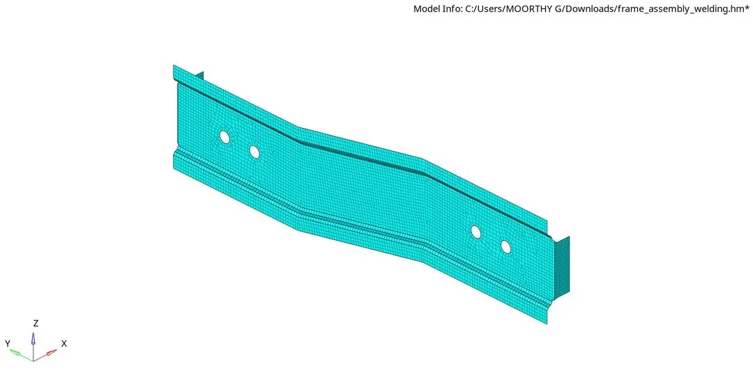
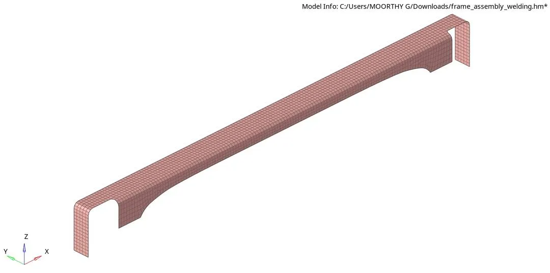
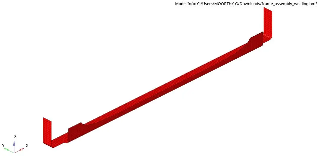
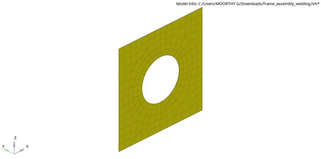
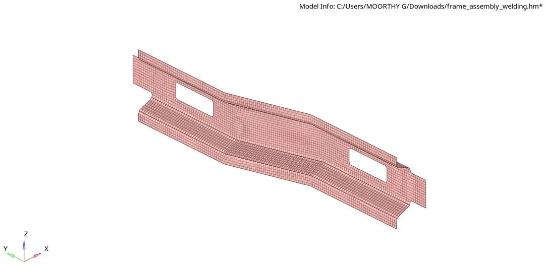
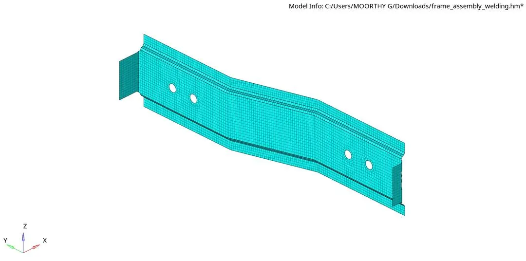
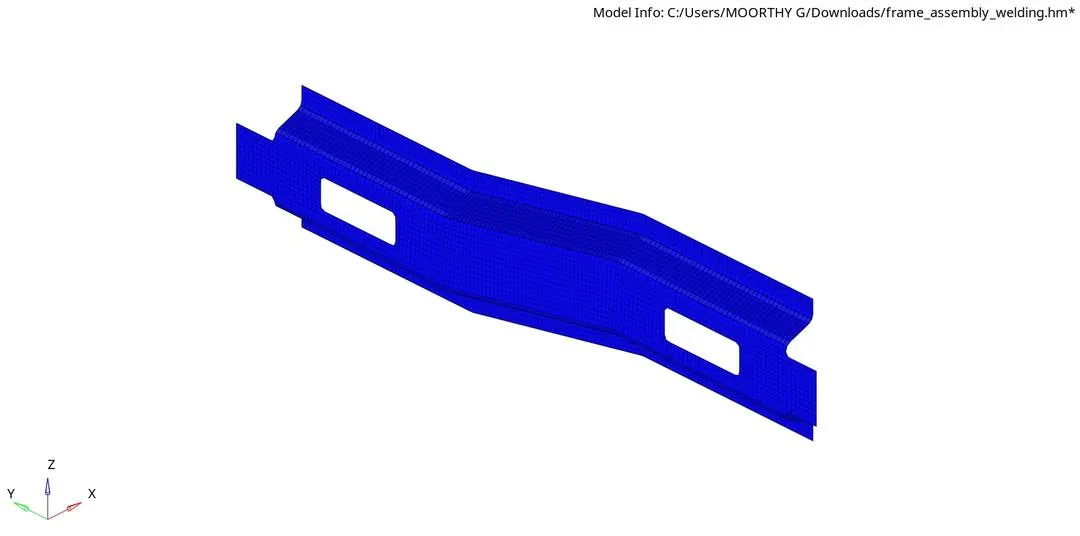
2D->Automesh->Surf->Displayed.
set the element size as 5 and element type as Mixed.
Step-5: Create connector.
1D or 2D or 3D->connectors.
1. Right Rail 2 & Front truss 1 - Seam-Quad(angled+capped+L).
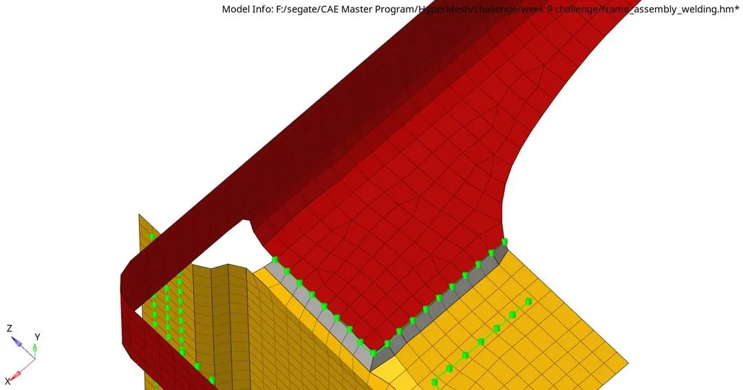
2. Left Rail 2 & Front truss 1 - Quad elements.
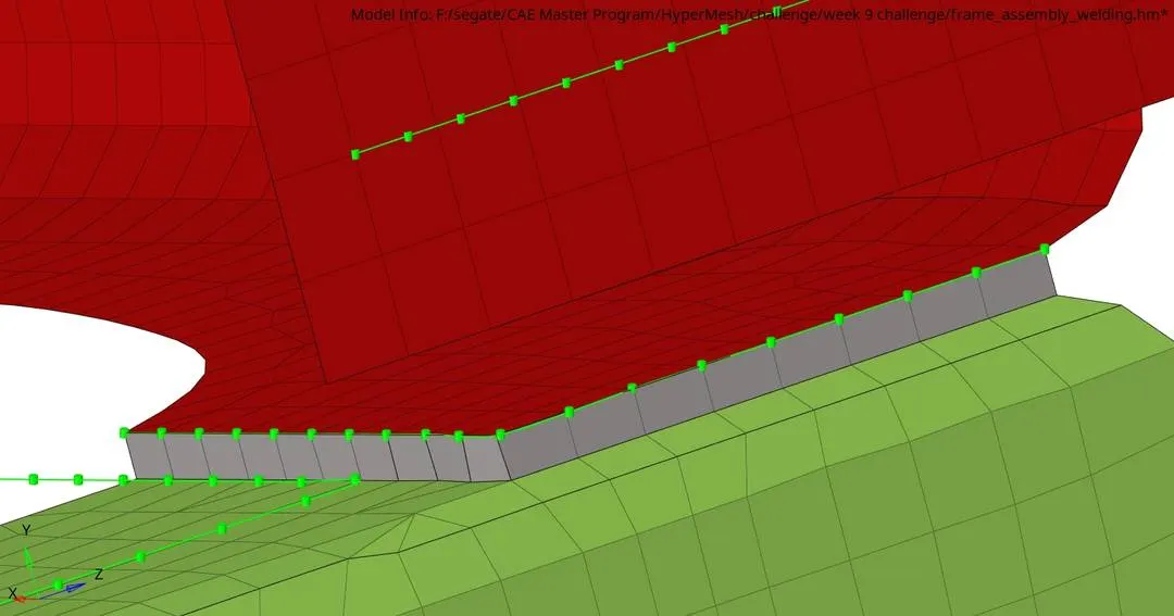
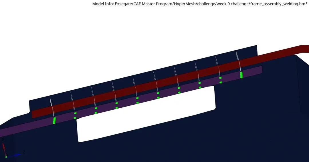
3. Front truss 2, Front truss 1 & Right Rail 1 - Spot weld with 3 Layers and 5 mm Diameter.
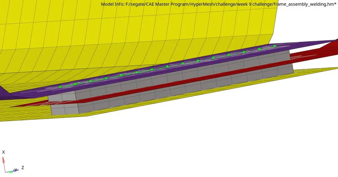
4. Front truss 2, Front truss 1 & Left Rail 1 - Hexa (Adhesive).
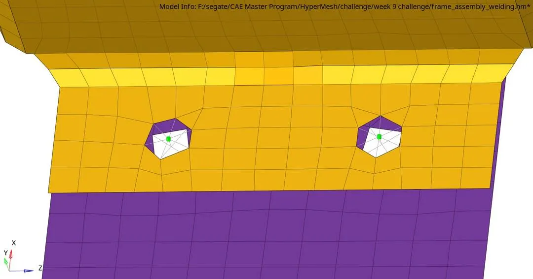
5. Rear truss 2 & Right Rail 2 - Bolt Connector.
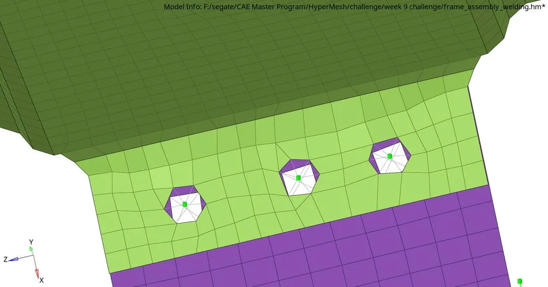
6. Rear truss 2 & Left Rail 2 - Bolt Connector.
7. Right Rail 1 & Right Rail 2 - Spot-weld with Rigid Elements.
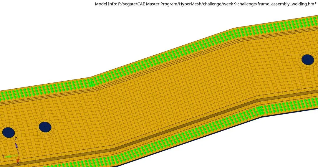
8. Left Rail 1 & Left Rail 2 - Spot-weld with Spring Elements.
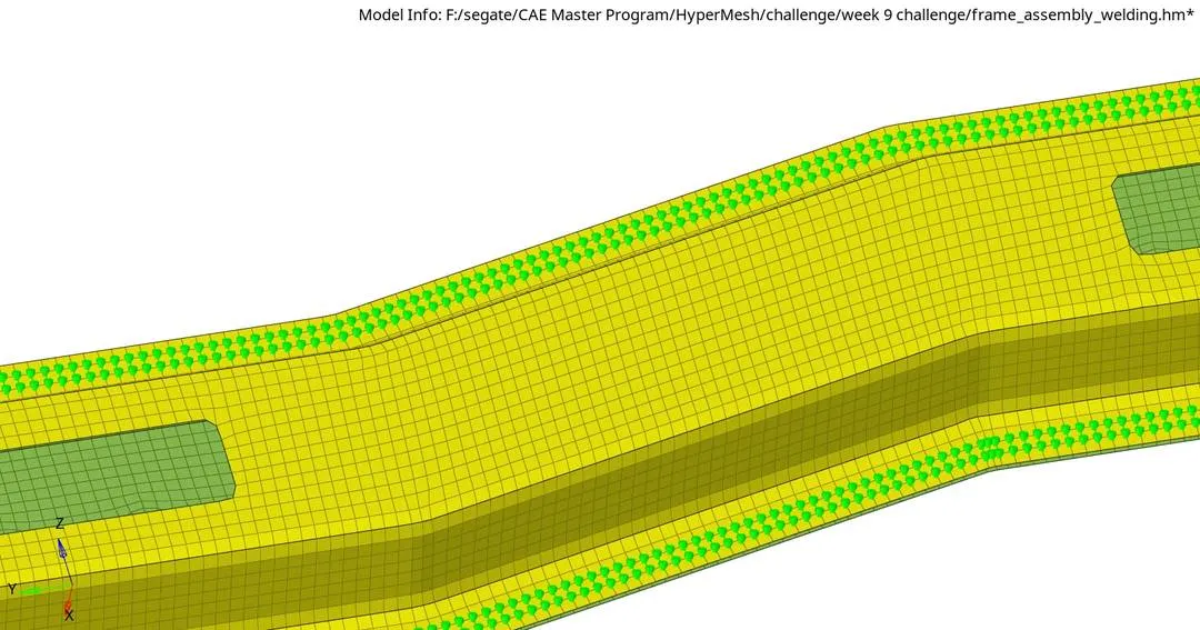
9. Front truss 1 & Reinf Plate - Seam-Quad(angled+capped+L).
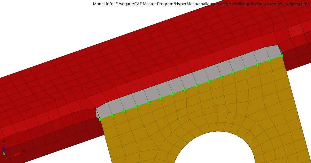
10. Front truss 2 & Reinf Plate - Seam-Quad(angled+capped+L).
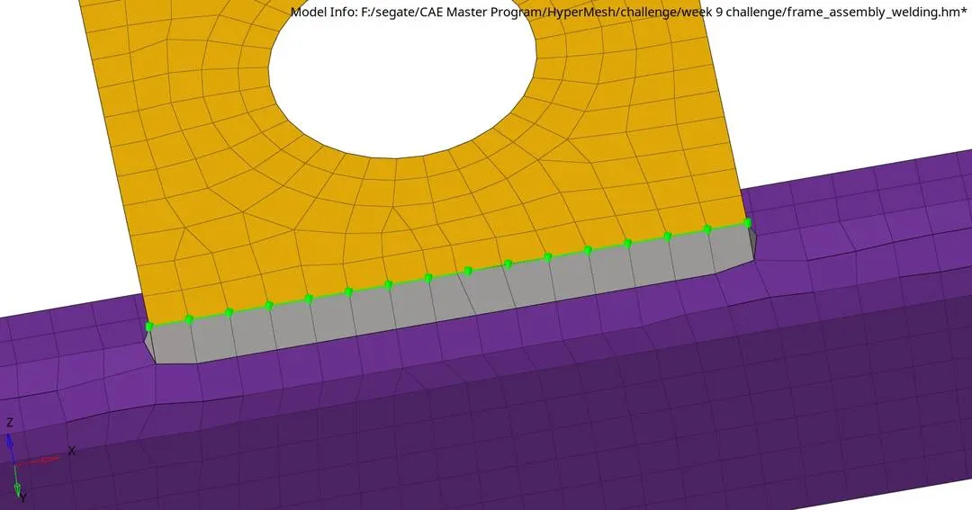
11. Front truss 2 & Right Rail 2 - Hexa (Adhesive).
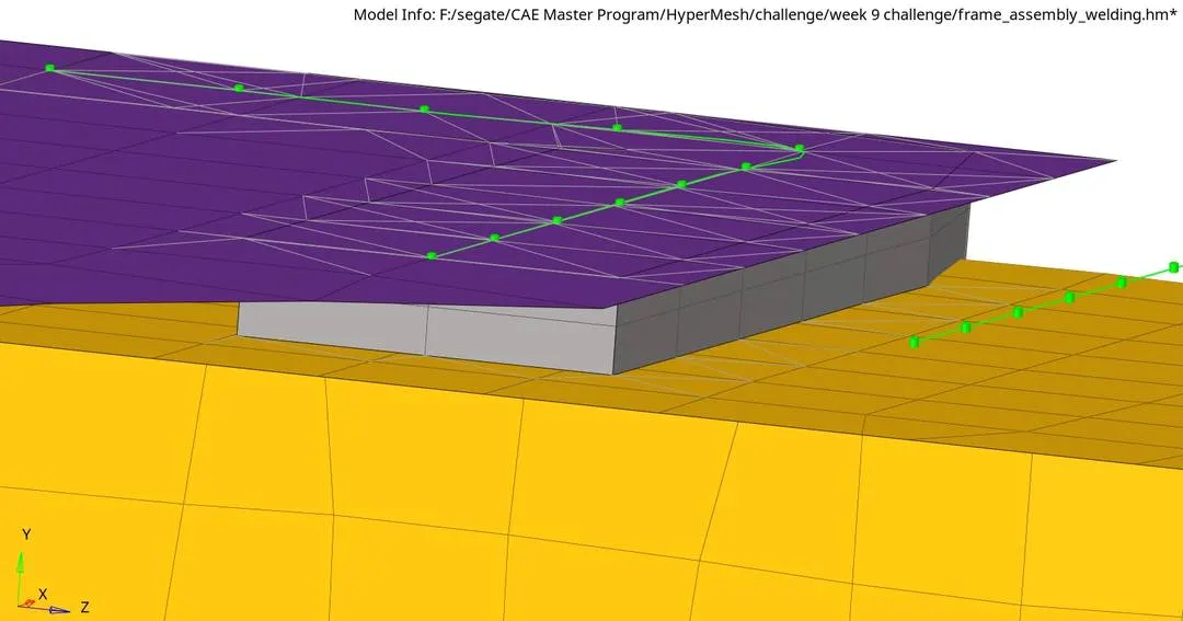
12. Front truss 1 & Left Rail 1 - Quad elements.
13. Left Rail 1 & Rear truss 2 - Spot-weld.
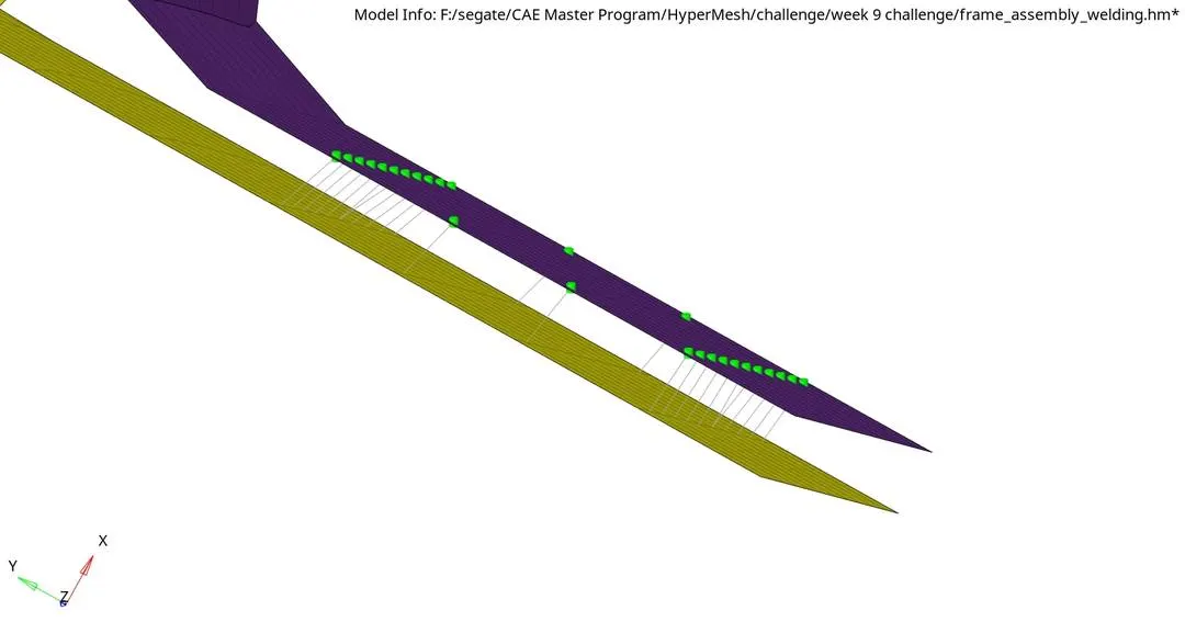
14. Rear truss 1 & Rear truss 2 - Spot-weld.

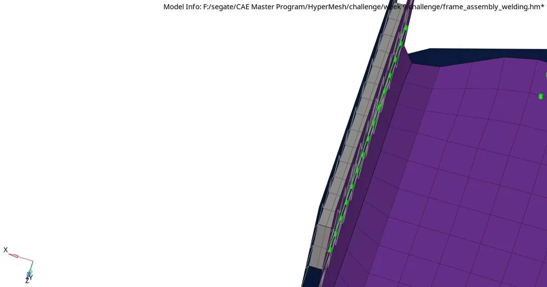
15. Rear truss 2 & Right Rail 1 - Hexa (Adhesive).
Step-6: Save.
RESULT:
The given Geomentry is meshed with 3D elements and components are joined (connected) with suitable connectors.
FINAL MODEL IMAGE: