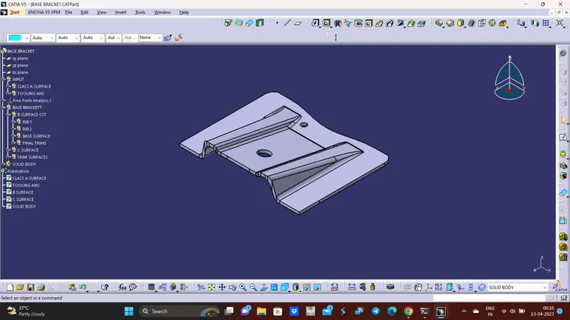
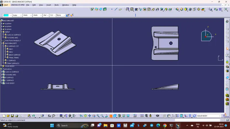
Week 9 - Challenge 1 - Base Bracket Design
DRAFT ANALYSIS
Class A surface
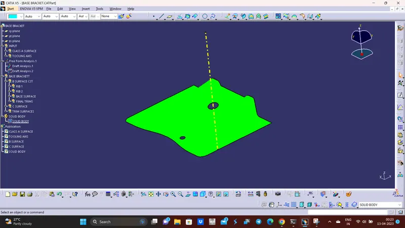
Final Plastic part
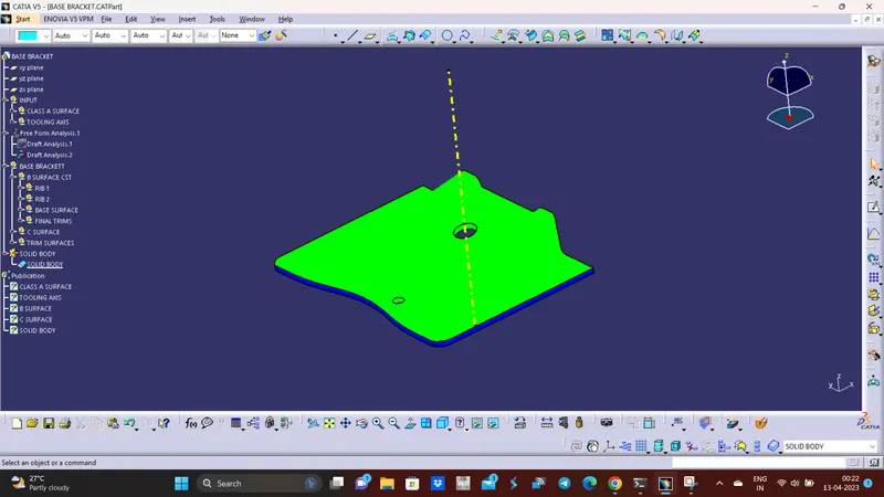
TOOLING AXIS CREATION
Procedure:
1. First create a dummy tooling axis using point and line definition
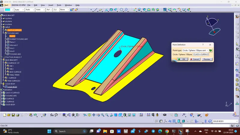
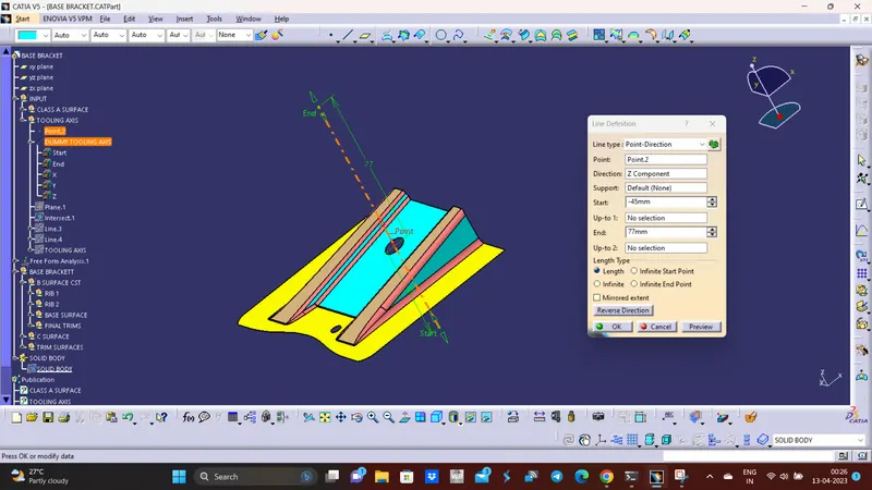
2. Next, create a plane using the reference plane and point.
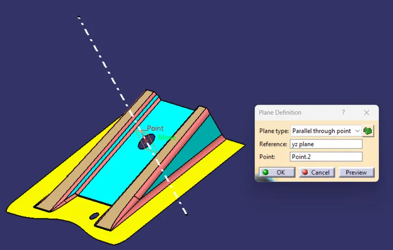
3. Now, perform the intersection definition for the plane and the class A surface
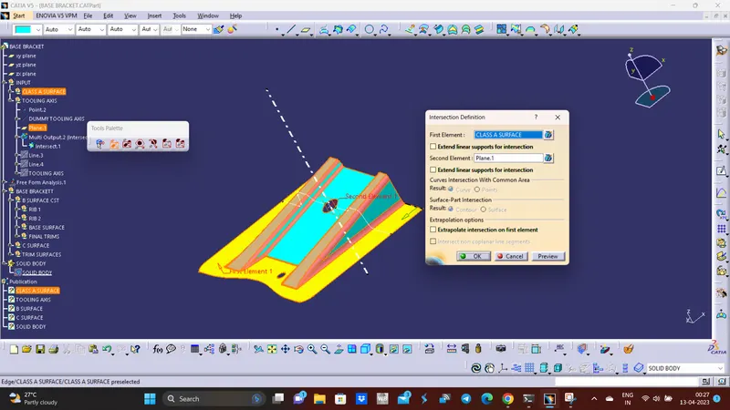
4. Once the intersection is done, hide the class A surface and use the intersect output to find the nearest point to the dummy tooling axis, so that it could be used as a tooling axis.
5. Create a line using the points on both sides.
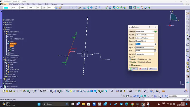
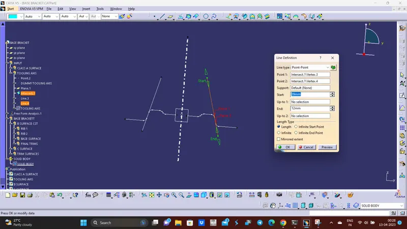
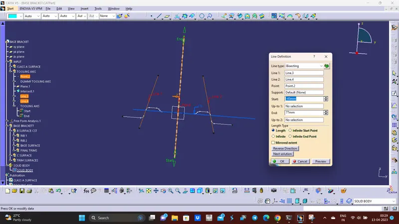
6. Now, with the two lines created, create a new line with line type as bisecting and click on the created lines for reference and the point created initially. We will get a bisecting line and the line in orange color is the tooling axis for the part.
SOLID MODEL