Week 9 - Challenge 1 - Base Bracket Design
BASE BRACKET CHALLENGE
In the given challenge , with the help of the link given of the Base bracket step file , I have made my required surfaces. Firstly , I opened the stp file in the Catia v5 and saved the converted file type. Then I opened the file and start my work.
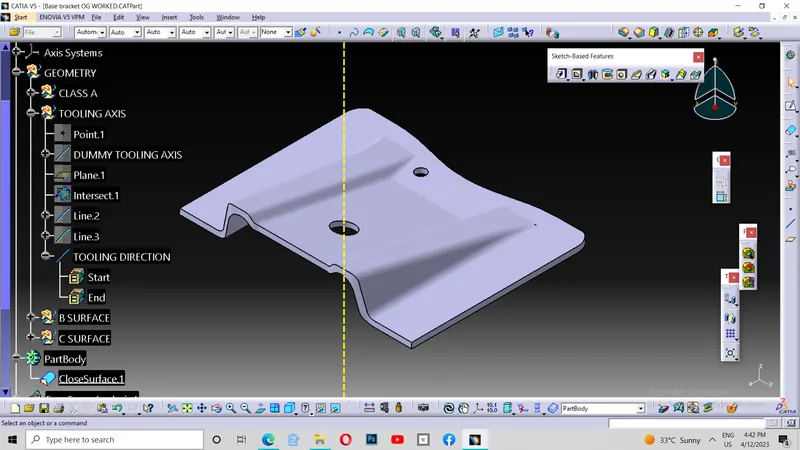
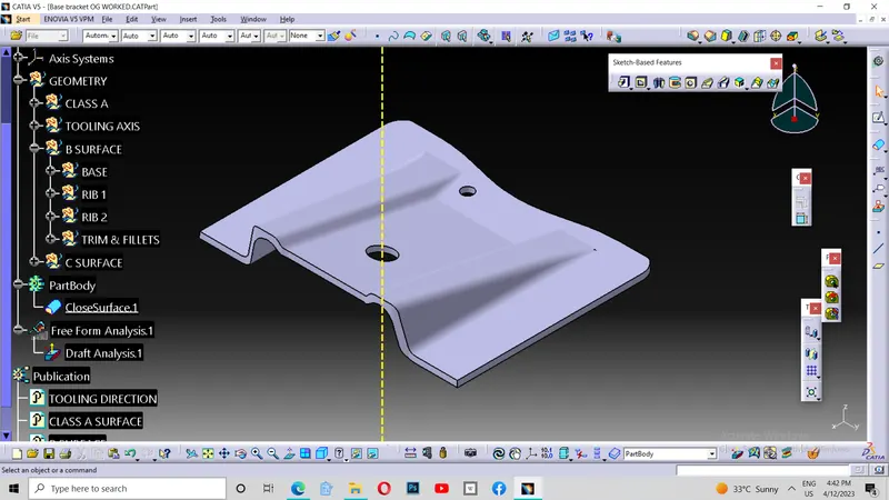
Firstly I craeted the geometrical set named class A and put the given class A surface into the geometrical set Class A .Then I created another geometrical set named Tooling axis. Then I start to create the Tooling axis .
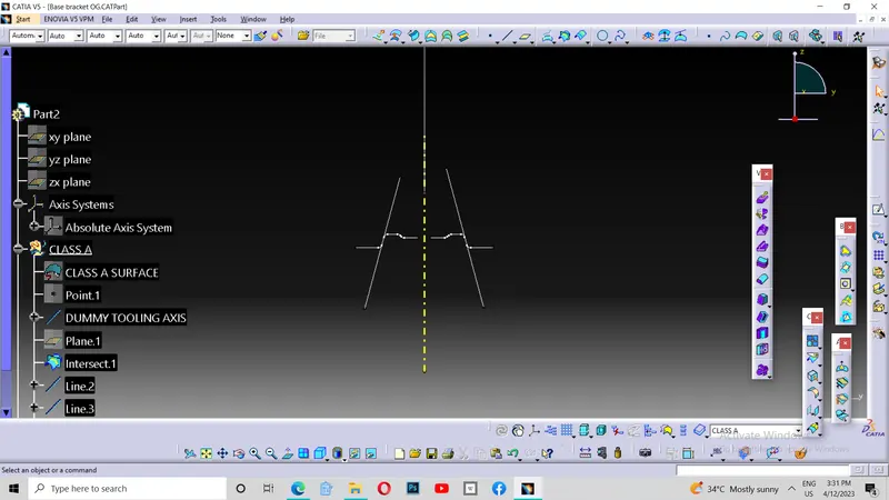
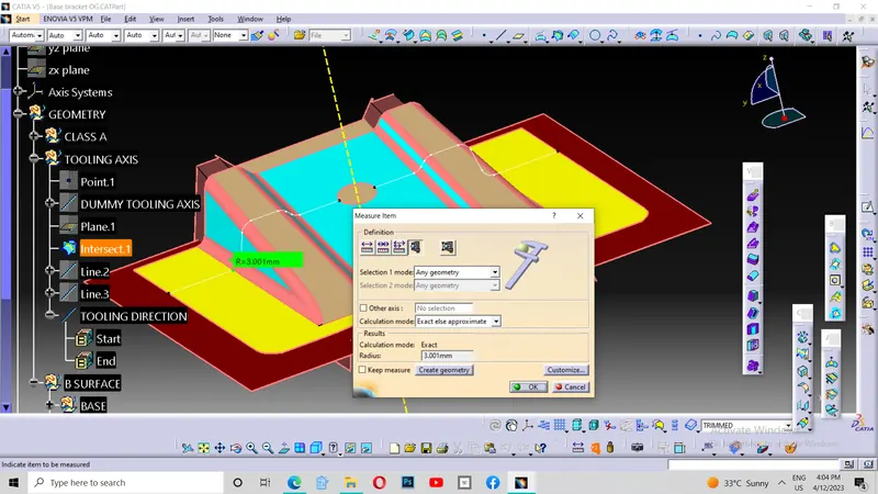
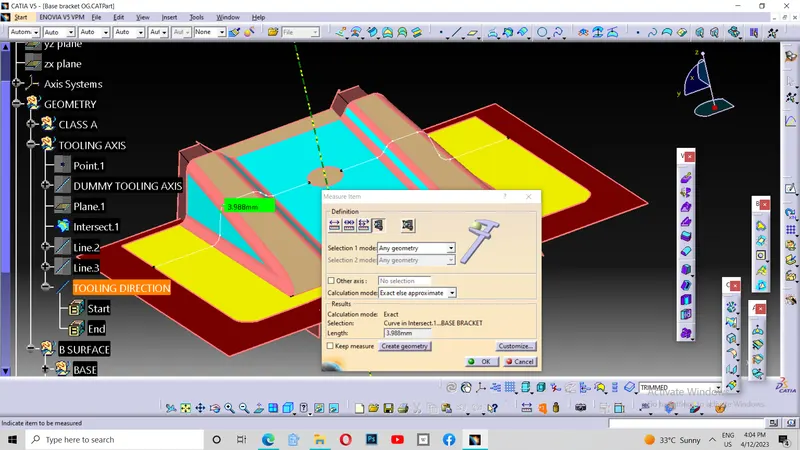
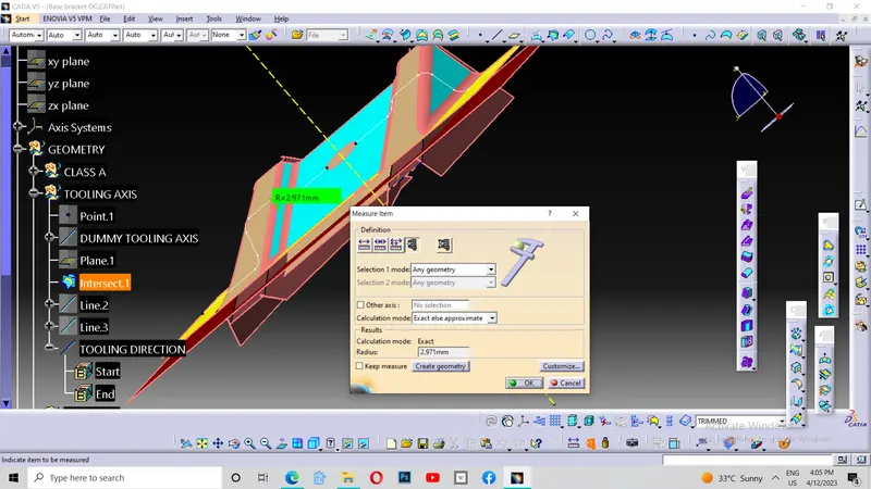
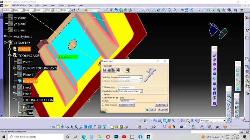
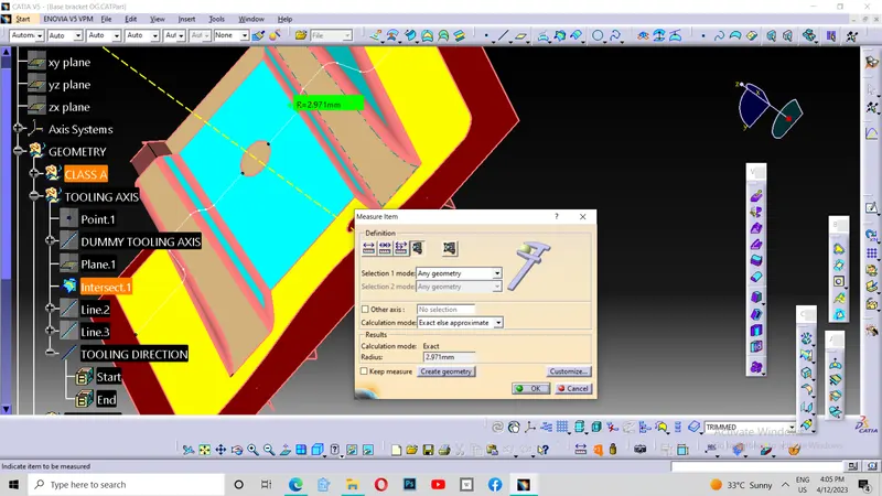
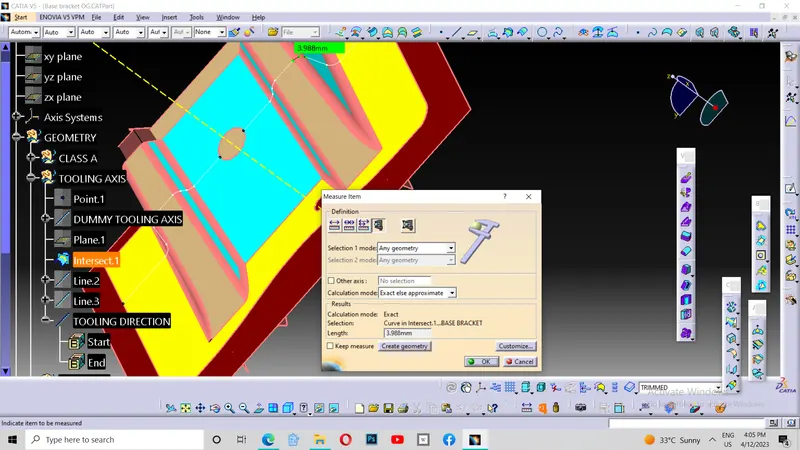
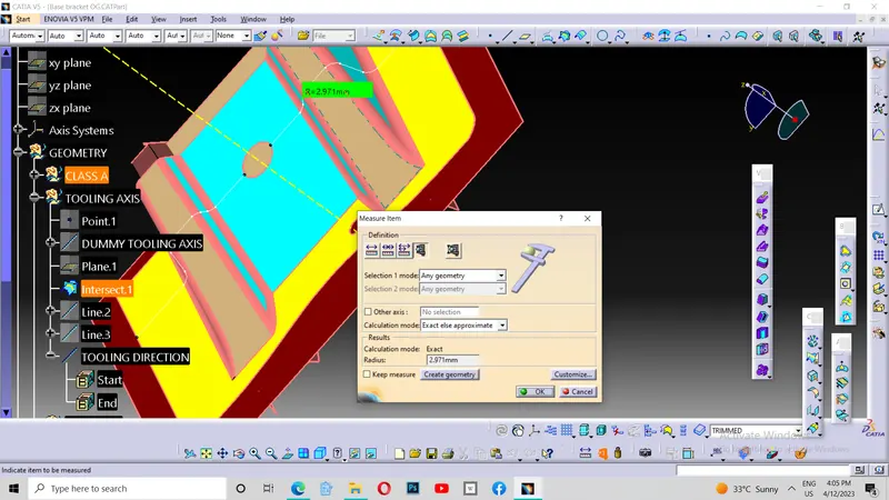
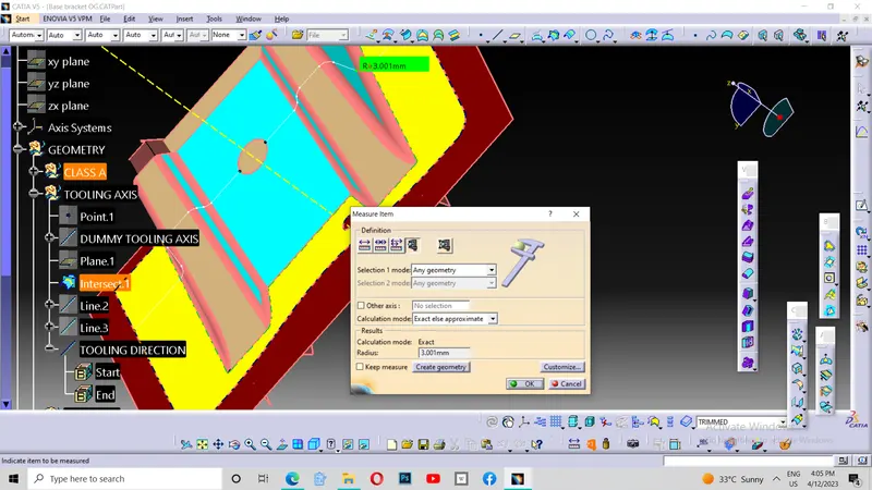
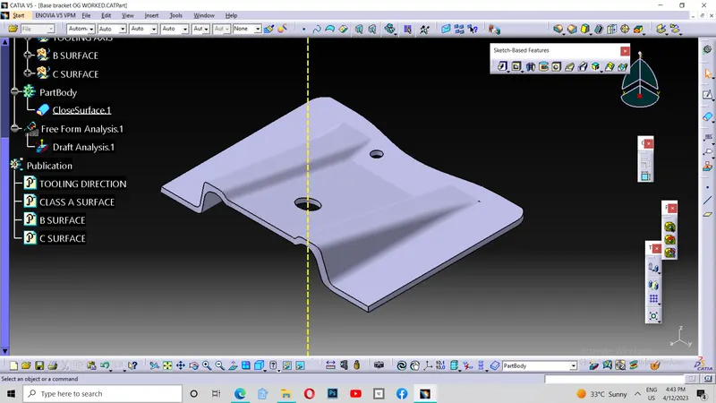
For the creation of the tooling axis, I have visualised the part in X , Y and Z axis and found the result that , the tooling direction must be in the X ot Z diection. Then due to the absence of vision of the another hole in the X direction, I have made the confirmation of the tooling axis in the Z direction. Therefor, I started to create a Dummy tooling axis. So I created a point in the middle of the circle of the hole which is in the base structure of the class A. Then I drawn a dummy line in Z direction by changing the colour of the axis and type of the axis and named it as Dummy tolling axis. Then I made a plane with the reference of YZ plane in the middle point. Then I made an intersect line with created plane and the body. Then after extenting the inclined lines , I have made a bisecting line of both the lines extented with the middle point as the reference and I got my required tooling axis and I confirmed it as the tooling axis. And I published Class A surface and the tooling axis.
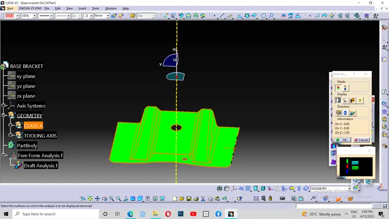
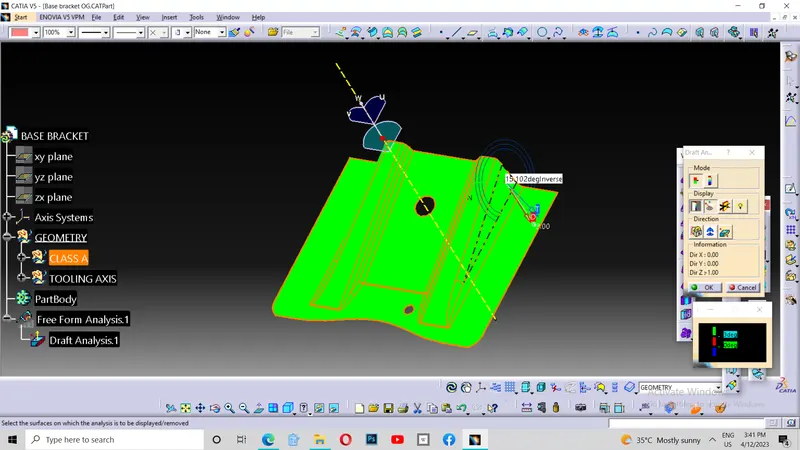
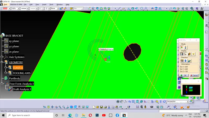
Then I analyzed the tooling direction with draft analysis and it shown the green colour in the nominal angle of 3 degrees. And I checked the inclinations of the inclined surfaces .
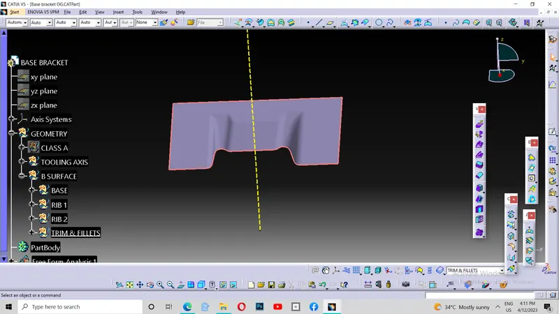
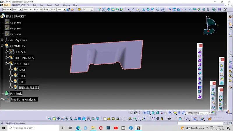
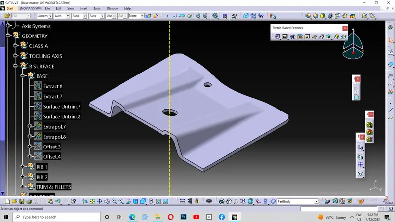
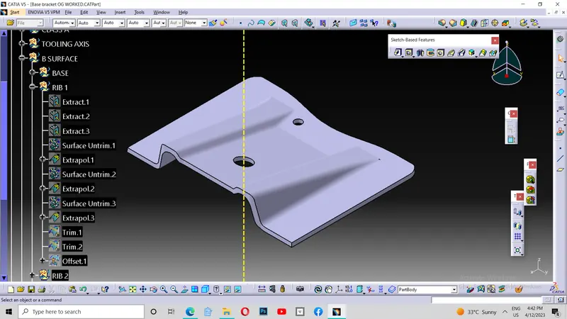
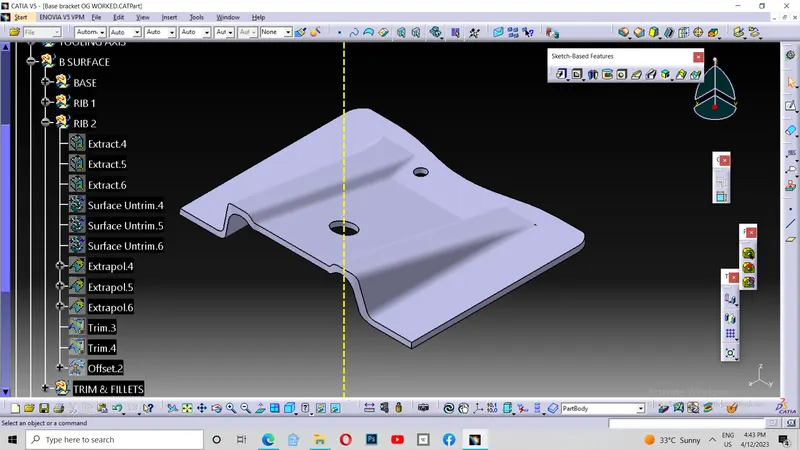
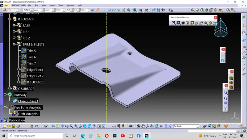
Then I made another geometrical set named B surface. Then I extracted the two ribs and base surfaces . Then I untrimmed every extracted surafces and extrapolated it point continuily in curvature . Then I trimmed the needed portions and offsetted it to 2.5 mm. After doing it to each extracted parts, I made my finalised trim and given the fillet values. I given the fillet values of 5.5 mm to each edge( 3 mm of class A and 2.5 mm of thickness). Thus I made my required B surface.
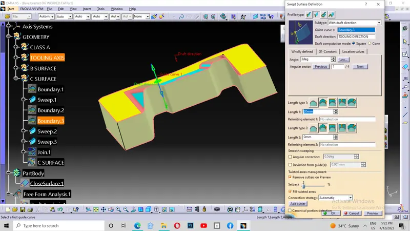
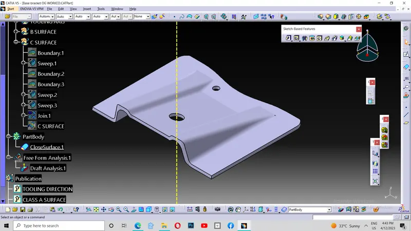
Then I started to create my C surface by creating a new goemetrical set named C surface. For the creation of the C surface , I took the boundary of the Class A and Sweeped it along draft direction as tooling axis with an angle of 3 degrees. Then I joined Class A with the C surface and trimmed it with B suface. And thus I got my required surface.
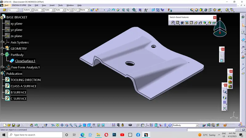
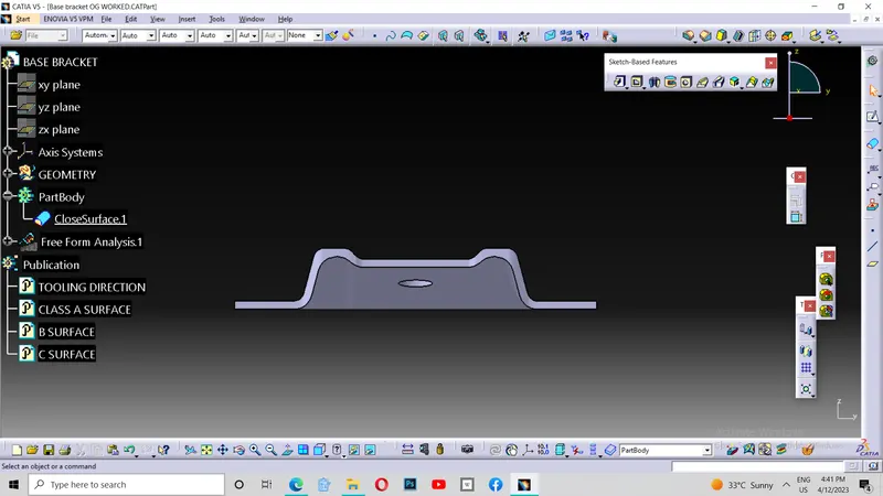
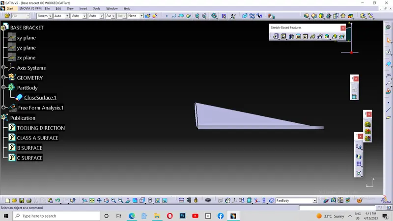
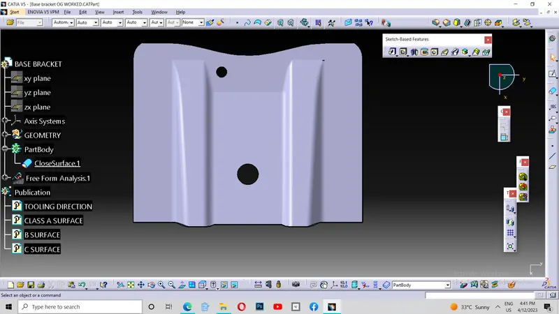
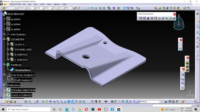
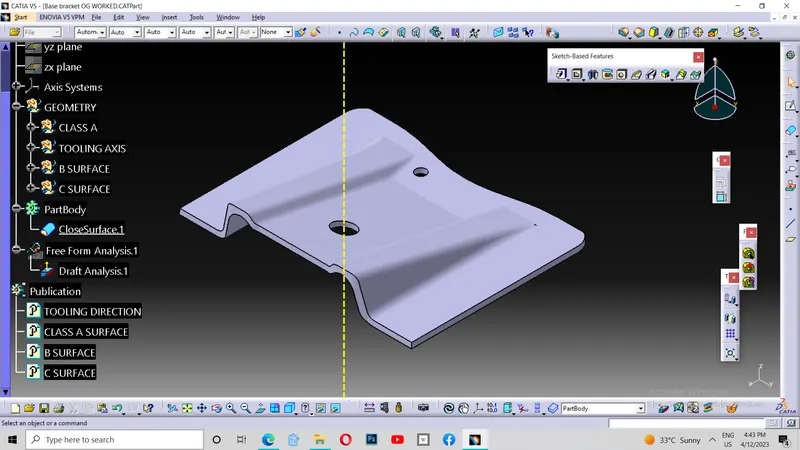
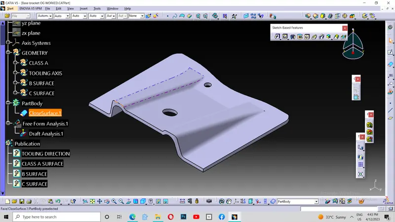
But it was hollow . So I made it closed by going to part design and made it closed with the help of close surface tool. THus I completed my challenge.