Week 9 - Challenge 1 - Base Bracket Design
SCREENSHOTS:
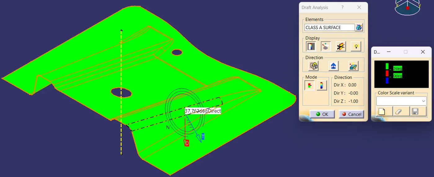
- CLASS A SURFACE:
- SOLID MODEL:
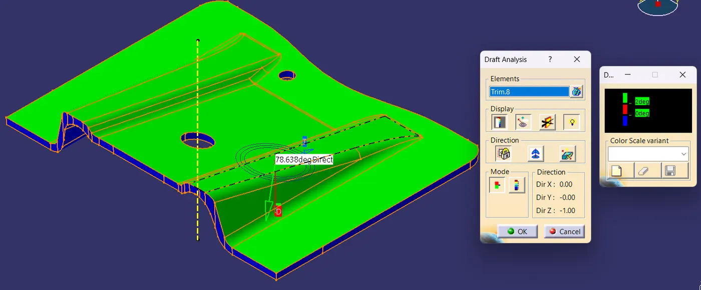
Isometric View
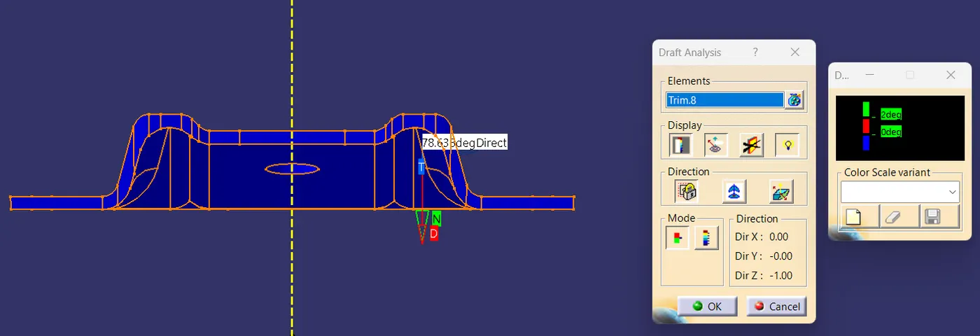
Front View
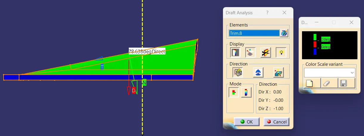
Side View
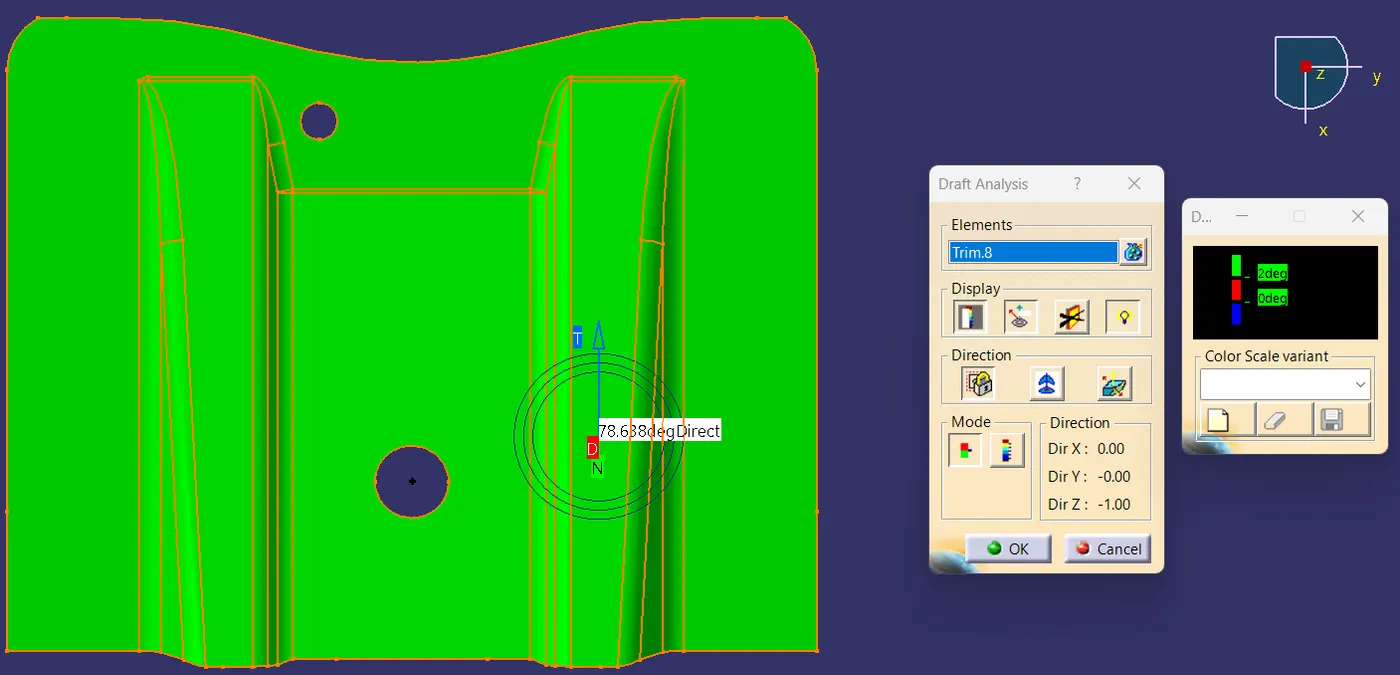
Top View
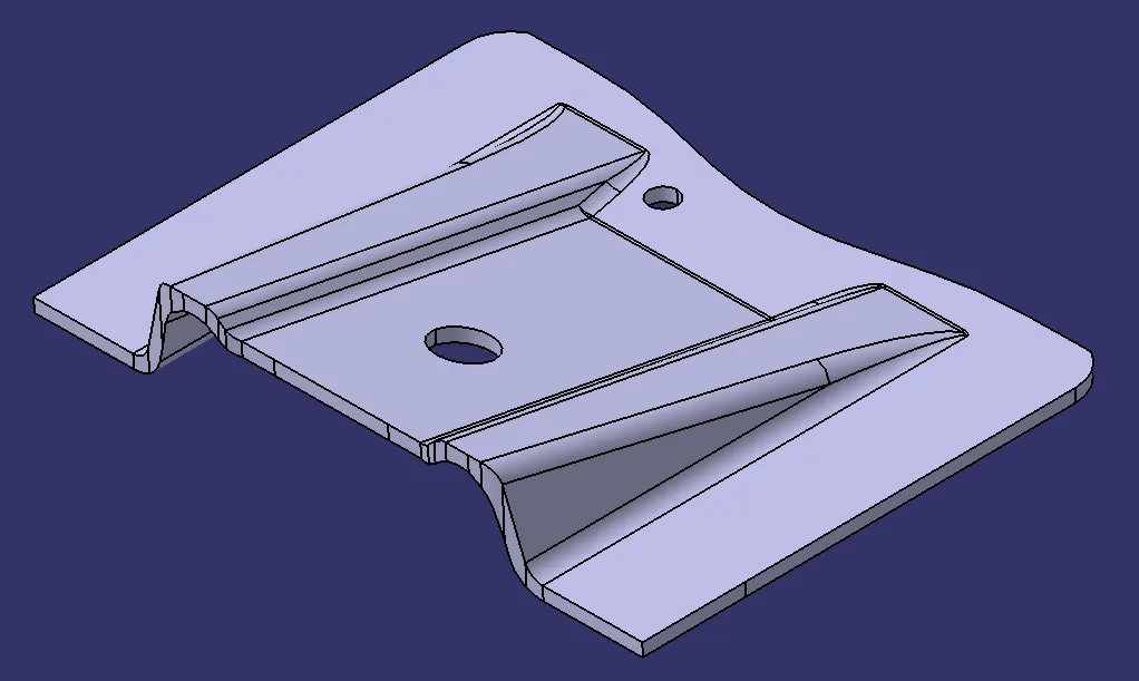
After using the Close Surface feature to make a solid body.
REPORT:
- Tooling Axis Creation and Draft Analysis:
- To create a Tooling axis to a part, first view the part in which direction the tooling can be done easily without any obstracle.
- As per our part the tooling axis should be in Z direction where the both holes can be obtained easily.
- Draw a dummy axis over the top hole by using line command and insert the yz plane.
- Then by the help of Intersect command obtain the intersecting line profile in order to get the real tooling axis.
- Draw the construction lines over the inclined surface on the intersecting profile on the both side.
- With the help of these construction lines we can obtain a real tooling axis by using the Bisecting Line type in line command.
- Then after getting the real Tooling axis go to inset>Analysis>Feature draft analysis.
- Make sure that the part is in the Material mode while performing the Draft analysis.
- Use the compass option in the draft analysis tab and place the compass over the tooling axis, this will ensure the draft analysis direction.
- The colour table will give the display information regarding the draft degree of the part.