Week 9 - Challenge 1 - Base Bracket Design
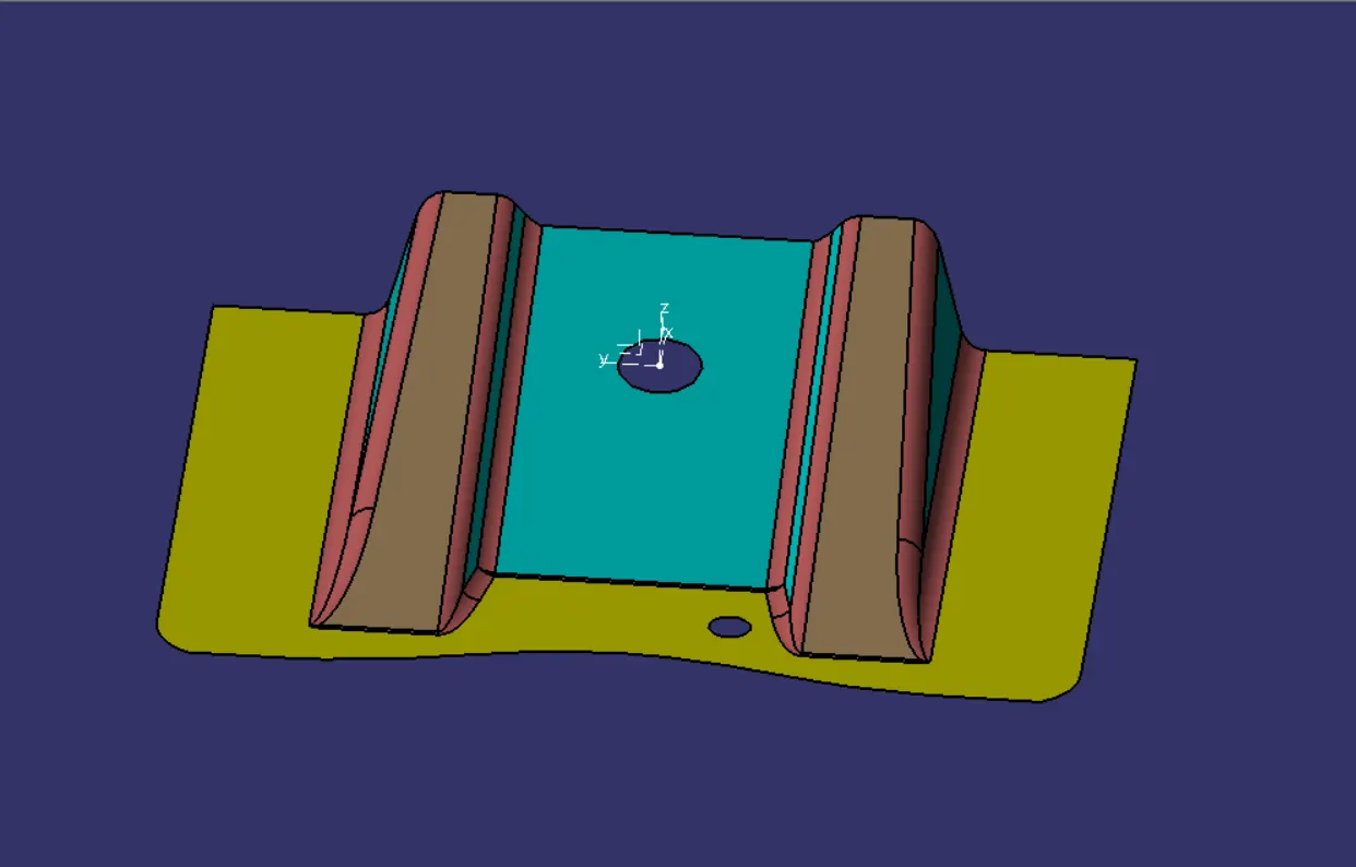
AIM: To create a base bracket plastic component through the given Class A surface.
OBJECTIVE:
- Ensure proper tree structure.
- All the sketchs should be created under the geometrical set.
- Geometrical sets should have a proper name based on the sketches present inside of it.
- Use closesurface to make a solid from the surface.
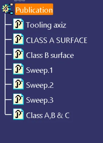
- Use publication command.
PROCEDURE:
- Verify the Class A surface point connectivity for finding any open cavity by using boundary or join commands.
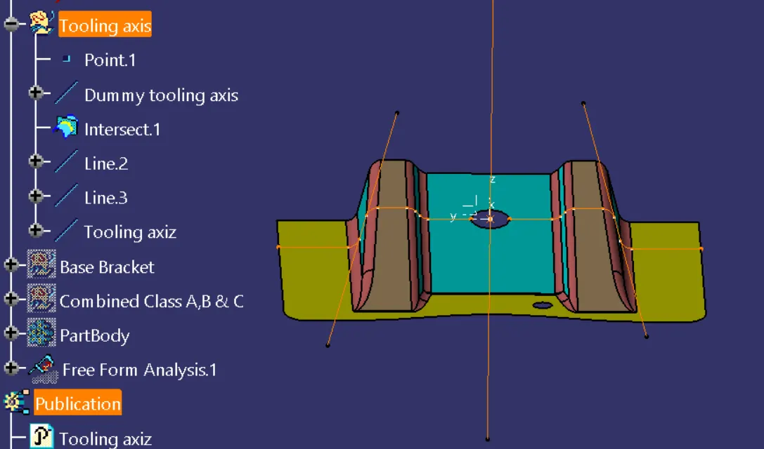
- Create Tooling axis by using bisecting method.
- Make Draft anlge analysis along the tooling axis.
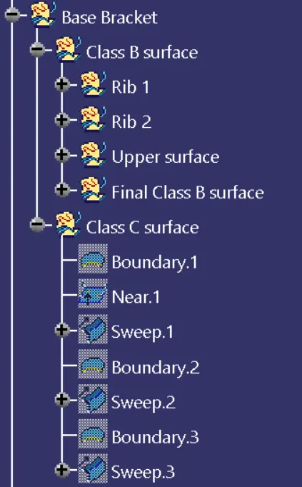
- Create Class B surface
- Create Class C surface
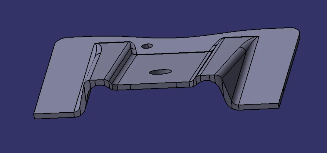
- Create solid body from the surfaces
EXPLANATION:
TOOLING AXIS:
Tooling axis is the direction in which the mould opening and closing operation is carried out during injection molding of plastic. It is used for deciding the draft angle of the component. In order to optimize the molding cost, the designer should have a clear view about the tooling axis while designing a any component for avoiding the unwanted side core.
CREATION PROCEDURE:
- Analyse visually for the best possible tooling axis
- Create dummy tooling axis
- Analyse the problem creating surface of the component along the perpendicular direction of the tooling axis
- After finding the problem creating surface, create intersection with the corresponding plane.
STEP 1:
- If the problem creating surface is along the x-axis, then the intersection will be carried out between xz plane and the corresponding surface.
- Create a line from the slopping surface on both sides by using point-point option.
- Then create the Tooling axis in between the two slopping line by using bisecting line and reference point option. This temporary tooling axis is created for critical surface which lies on x-direction
STEP 2:
- The same above procedure is followed if the slope or inclined surface lies along y-direction
STEP 3:
- By using Bisecting line option, the original tooling axis is created from two temporary tooling axis which lies on the X-direction and Y-direction
NOTE: If the inclined surface is found only on any one of the direction (either X-dir or Y-dir) , then will take the temporary tooling axis on either STEP 1 or STEP 2 as main tooling axis.
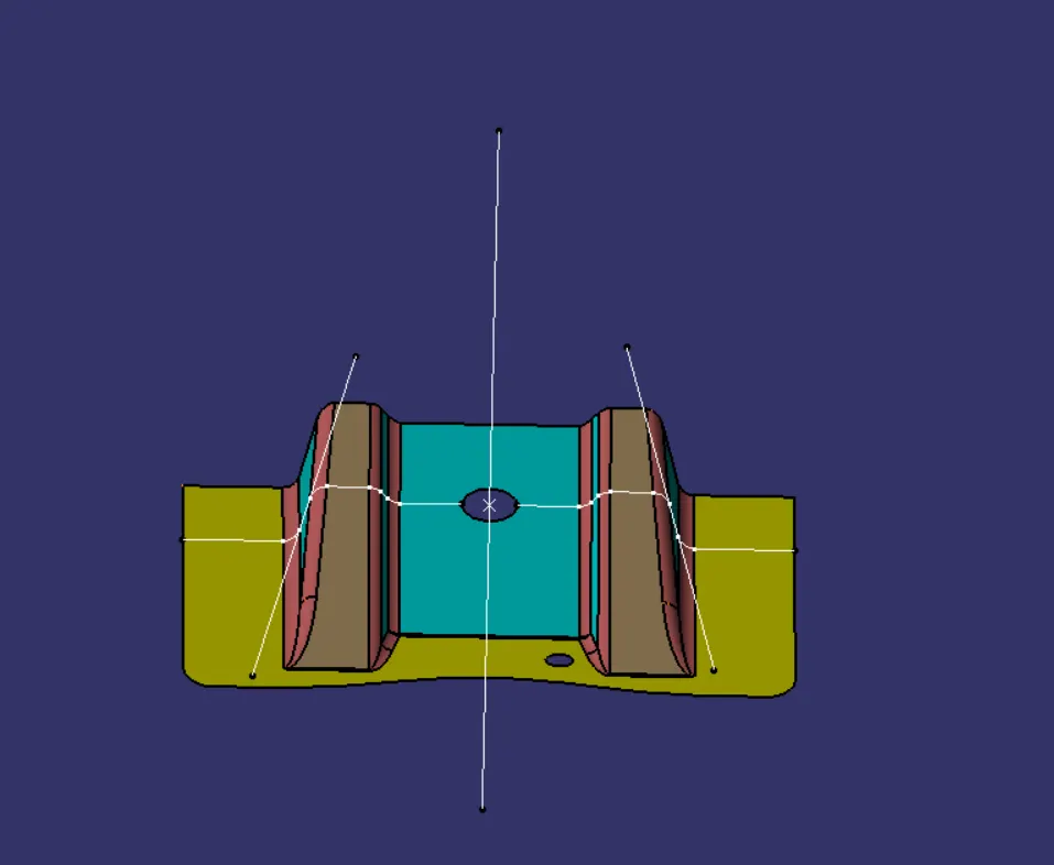
DRAFT ANALYSIS:
Draft analysis is precaution method to avoid difficulties which are all facing during mold creation. Draft analysis is done along the main tooling axis. This analysis is used for the smooth ejaculation of the component from the mold after casting.
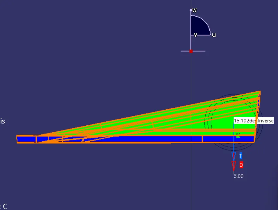
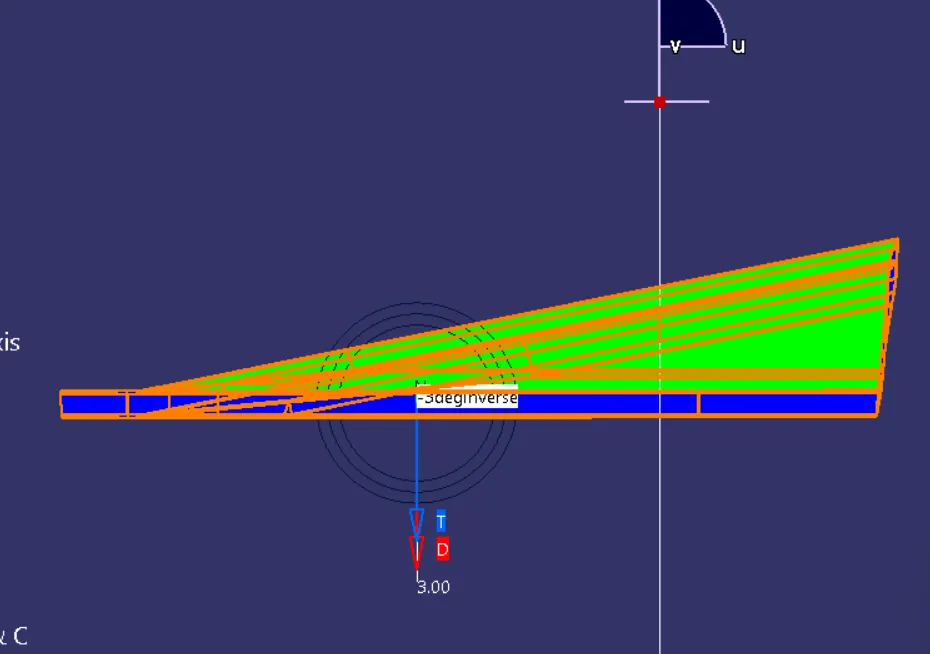
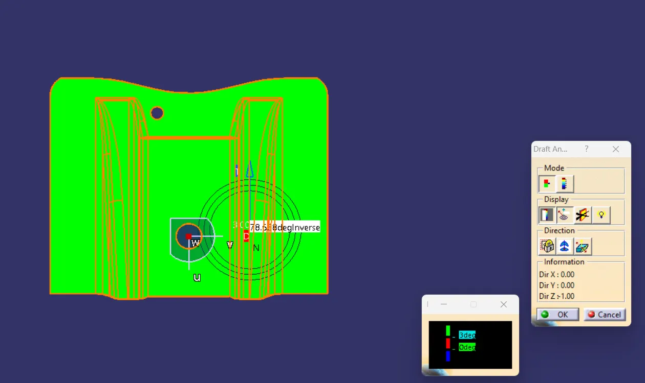
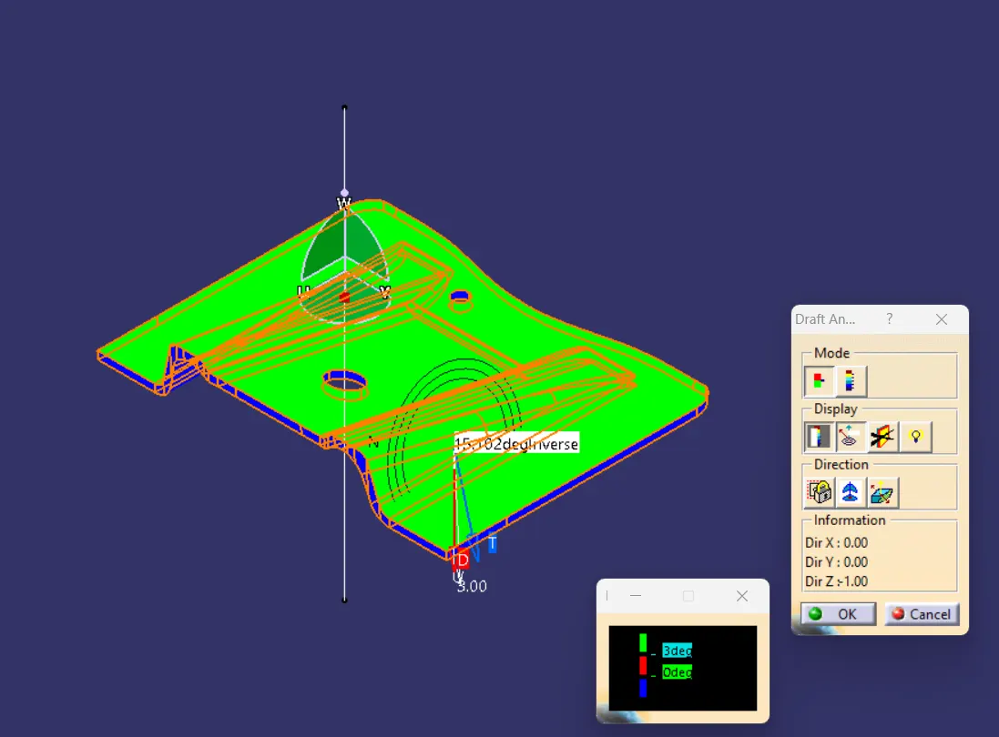
In draft analysis, the reference axis is taken as main tooling axis and the nominal draft value (3 deg) is given as deciding factor. The surfaces of the component with reference to the main tooling axis, which deviates from the given nominal value are shown as red color. If there is no deviation, the surfaces will turn into either green or blue. This analysis should be done before creating the Class B and Class C surface.
CLASS A SURFACE DRAFT ANALYSIS:
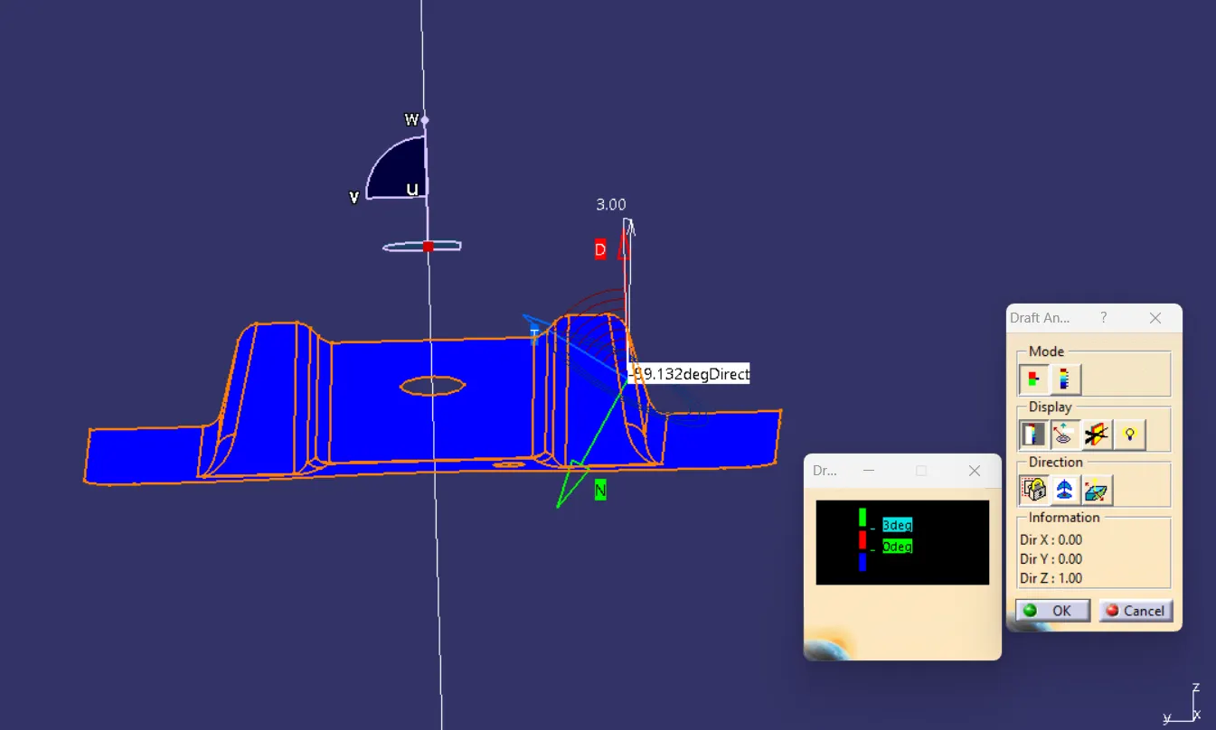
DRAFT ANALYSIS ON FRONT VIEW OF SOLID BODY:
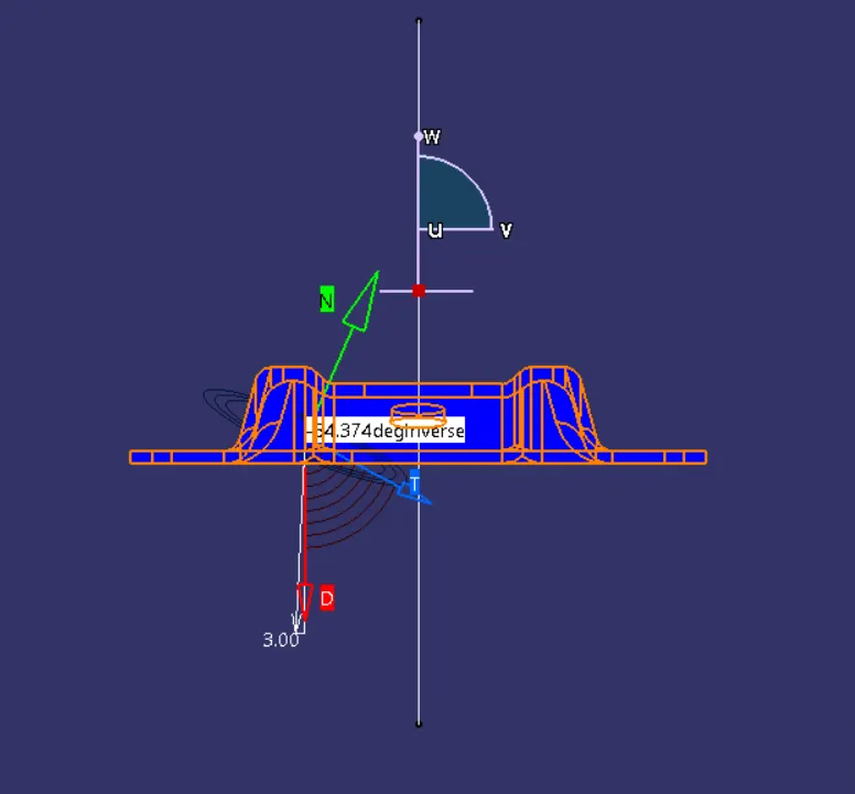
DRAFT ANALYSIS ON SIDE VIEW OF SOLID BODY:
DRAFT ANALYSIS ON TOP VIEW OF SOLID BODY:
DRAFT ANALYSIS ON ISOMETRIC VIEW OF SOLID BODY:
TREE STRUCTURE:
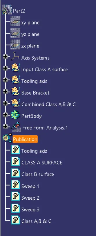
INPUT CLASS A SURFACE:
TOOLING AXIS:
BASE BRACKET TREE STRUCTURE;
CREATION OF RIB 1 AND RIB 2:
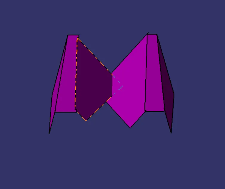
CLASS B SURFACE:
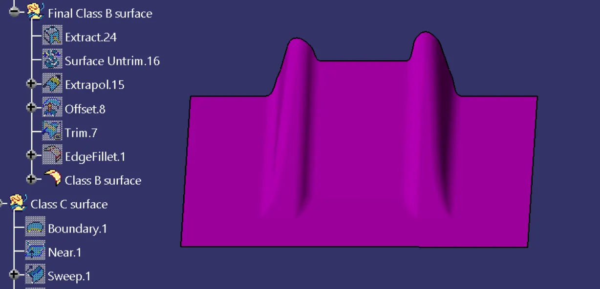
CLASS C SURFACE:
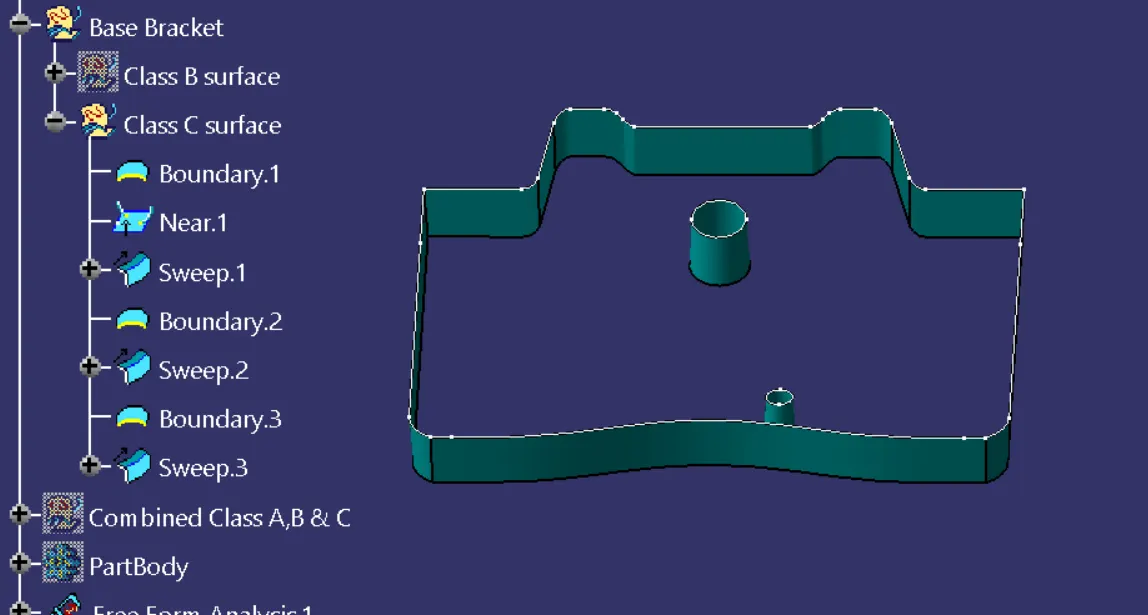
TRIMMING OF CLASS A, B & C SURFACE:
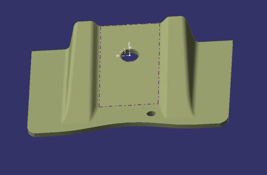
SECTION VIEW:
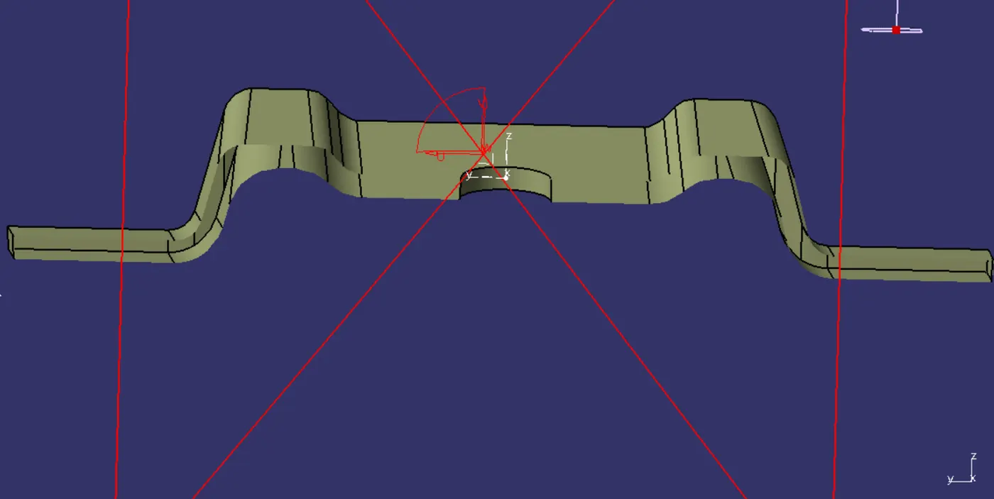
SURFACE CONVERTED INTO SOLID PART BODY BY USING CLOSESURFACE COMMAND:
PUBLICATION: